Fabric configuration Walkthrough using Juniper Apstra
This section describes the steps to deploy one of the AI GPU Backend IP fabrics in the AI JVD lab, as an example of how to deploy new fabrics, using Juniper Apstra.
These steps will cover the AI GPU Backend IP fabric using QFX5220-32CD and QFX5230-64CD switches in the spine and leaf role. Similar steps should be followed to set up the Frontend and Storage Backend fabrics.
The section also provides configuration steps for the Nvidia GPU servers.
Setting up the Apstra Server
A configuration wizard launches upon connecting to the Apstra server VM for the first time. At this point, passwords for the Apstra server, Apstra UI, and network configuration can be configured.
For more detailed information about installation and step-by-step configuration with Apstra, refer to the Juniper Apstra User Guide.
Onboarding devices in Apstra
There are two methods for adding Juniper devices into Apstra:
- Using ZTP
From the Apstra ZTP server, follow the ZTP steps described in the Juniper Apstra User Guide.
- Manually (covered in detail in the next section)
It is best practice to avoid setting loopbacks, interfaces (except management interface), routing-instances (except management-instance) or any other settings as part of this baseline configuration.
Apstra sets the protocols LLDP and RSTP when the device is successfully Acknowledged.
To onboard each device, follow these steps in the Apstra Web UI:
Onboarding devices in Apstra steps
Step 1: Create Agent Profile for Junos devices.
- Navigate to Devices >> Agent Profiles
- Click on Create Agent Profile.
Figure 23. Create Agent Profile in Apstra
 NOTE: For the purposes of this JVD, the same username and password are used across all devices. Thus, only one Junos Agent Profile is needed to onboard all the devices.
 - Enter the Agent profile name, select platform (Junos), and
enter the username and password that will be used by Apstra to
communicate with the devices.
- This requires that the devices are preconfigured with a root password, the username and password configured in Apstra, a management IP and proper static routing if needed, as well as ssh Netconf, so that they can be accessed and configured by Apstra.
Figure 24: Apstra Agent Profile Parameters
- After entering the required information, click Create.
- Confirm Agent Profile creation.
Figure 25: New Apstra Agent Profile Verification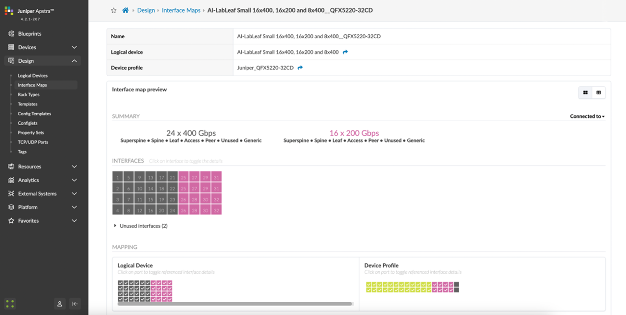
Step 2: Create Agent Profile for other devices.
- Navigate to Devices >> Agent Profiles
- Click on Create Agent Profile.
Figure 26. Create Agent Profile in Apstra
.png)
- Enter the Agent profile name, select platform (Junos), and
enter the username and password that will be used by Apstra to
communicate with the devices.
This requires that the devices are preconfigured with a root password, the username and password configured in Apstra, a management IP and proper static routing if needed, as well as ssh Netconf, so that they can be accessed and configured by Apstra.
Figure 27: Apstra Agent Profile Parameters
- After entering the required information, click Create.
- Confirm Agent Profile creation.
Figure 28: New Apstra Agent Profile Verification
Step 3: Create Offbox Agents for QFX devices.
- Navigate to Devices >> Managed Devices
- Click on Create Offbox Agents. Make sure
you select Offbox Agent(s).
Figure 29: Create Offbox Agent in Apstra
- Identify the device(s) to onboard.
You can enter a comma-separated list of hostnames, individual IP
addresses, or IP address ranges.
NOTE: An IP address range can also be provided to onboard multiple devices in Apstra at once. The ranges shown in the example below are shown for demonstration purposes only.
- Select the platform, and Agent Profile (select
the profile created in the previous step).
Figure 30: Identifying the device(s) to onboard using a range of IP Addresses
NOTE: Apstra uses the information from the profile that was created in the previous step, if “ Set username?” and “ Set password?” are unchecked.
- Click Create.
- Confirm that the devices have been added for onboarding. Once the offbox agent has been created, devices will be added to the list of Managed Devices. Apstra will attempt to connect, and if successful, it will populate the relevant information.
Figure 31: New devices being onboarded
Step 4: Create Onbox Agents and onboard AMD servers.
- Navigate to Devices >> Managed Devices
- Click on Create Onbox Agents. Make sure
you select Onbox Agent(s).
Figure 32: Create Onbox Agent in Apstra
- Identify the device(s) to onboard.
You can enter a comma-separated list of hostnames, individual IP
addresses, or IP address ranges.
NOTE: An IP address range can also be provided to onboard multiple devices in Apstra at once. The ranges shown in the example below are shown for demonstration purposes only.
- Select the platform, and Agent Profile (select
the profile created in the previous step).
Figure 33: Identifying the device(s) to onboard using a range of IP Addresses
 NOTE: Apstra uses the information from the profile that was created in the previous step, if “ Set username?” and “ Set password?” are unchecked,
 - Click Create.
- Confirm that the devices have been added for onboarding. Once the onbox agent has been created, devices will be added to the list of Managed Devices. Apstra will attempt to connect, and if successful, it will populate the relevant information.
Figure 34: New devices being onboarded
Step 5: Acknowledge Managed Devices for Use in Apstra Blueprints.
The devices must be acknowledged by the user to complete the onboarding and allow them to be part of Apstra Blueprints.
Once the offbox agent creation has been successfully executed for each device, the devices must be acknowledged by the user to complete the onboarding and make them part of the Apstra Blueprints. This moves the device state from OOS-QUARANTINE to OOS-READY.
- Select device(s)
- Click on the “Acknowledge selected system button”
Figure 35: Acknowledging Managed Devices in Apstra Blueprints
Fabric Provisioning in the Apstra Web UI
To provision the fabric, follow these steps in the Apstra Web UI:
Step 1: Create Logical Devices and Interface maps for leaf and spine nodes.
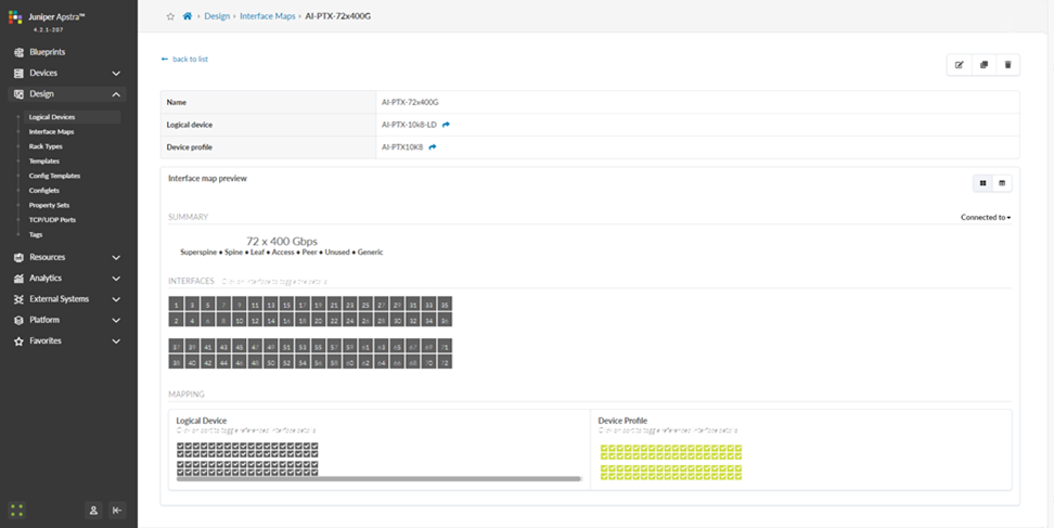
The example shows how to create the interface map and Logical device for the PTX10008 with LC1301 spine nodes.
- Navigate to Design > Logical Devices
- Click on Create Logical Device.
Figure 36: Creating a Logical Device
- Provide a name, add additional ports, and change the speed to 800G.
- Click on Add Pannel.
Figure 37: Creating Logical Device Panel 1.
- Provide a name, add additional ports, and change the speed to
800G on the second panel.
Figure 38: Creating Logical Device Panel 2.

- Click on Create Port Group for panels 1 and 2.
Figure 39: Creating Logical Device Port groups.
- Click Create.
Figure 40: Creating Logical Device
- Verify Logical Device Creation.
Figure 41: New Logical Device

- Navigate to Design > Logical Devices
Figure 42: Creating an Interface Map
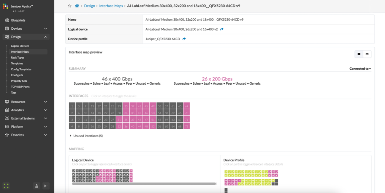
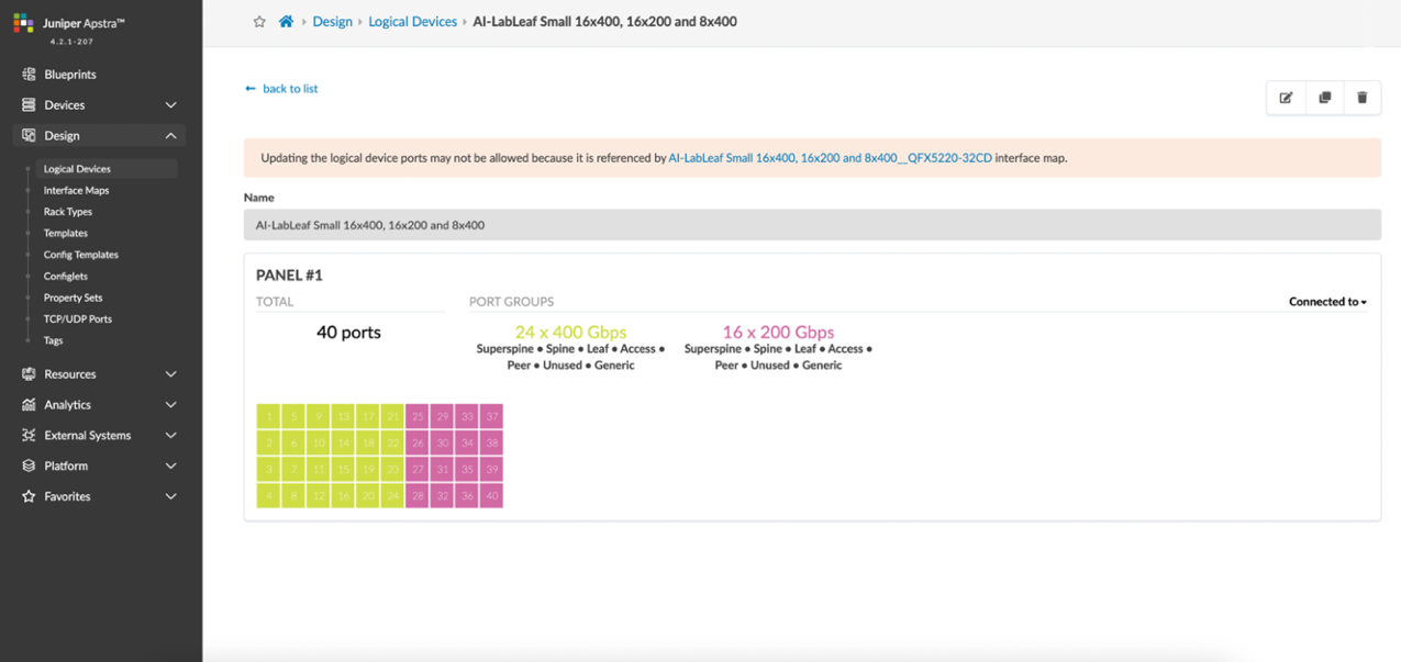
For the QFX5220 leaf nodes, the Logical Device and Interface Map are shown in Figures 43 and 44:
Figure 43: Apstra Logical Device for the QFX5220 Leaf Nodes
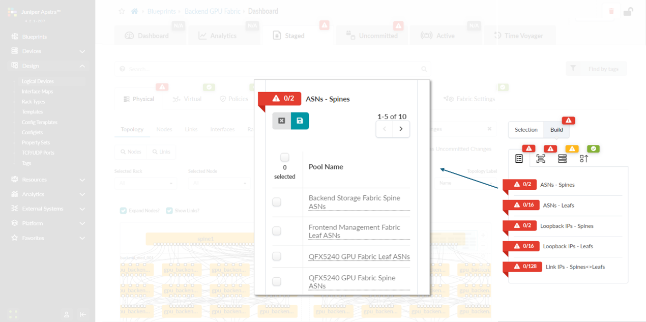
Figure 44: Apstra Interface Map for the QFX5220 Leaf Nodes
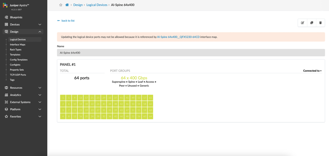
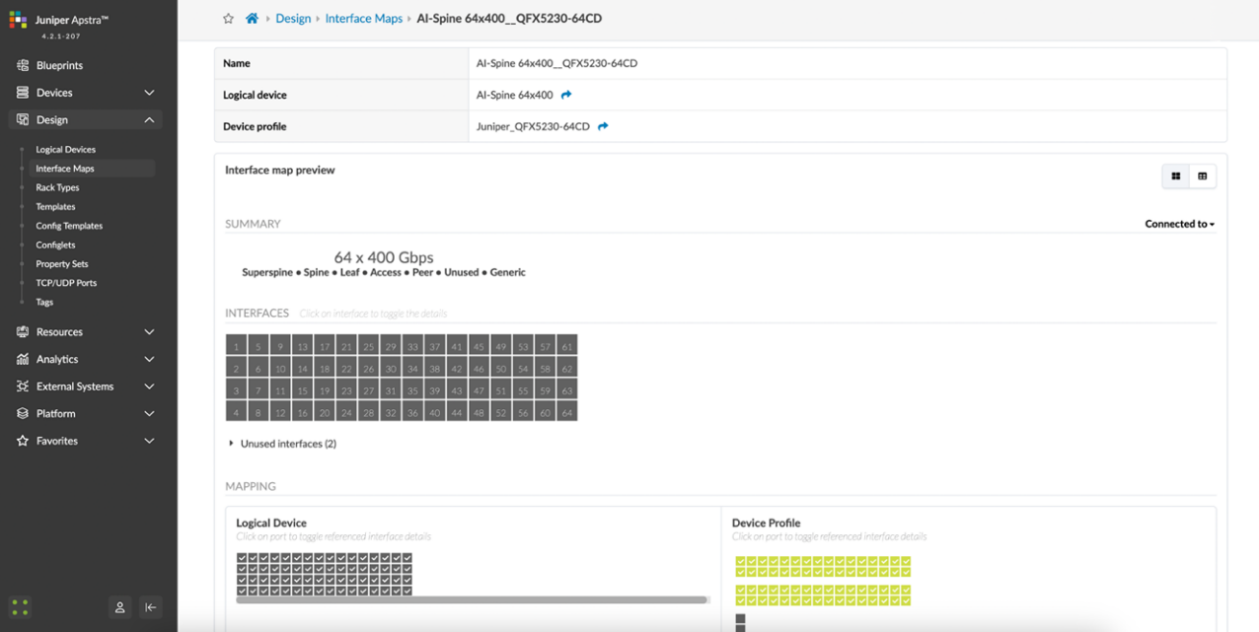
For the QFX5230-64CD leaf nodes, the Logical Device and Interface Map are shown in Figures 45 and 46:
Figure 45: Apstra Logical Device for the QFX5230 Leaf Nodes
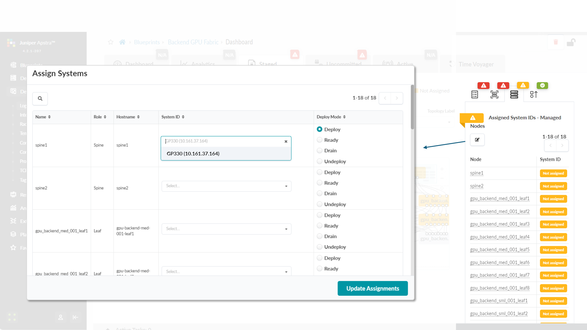
Figure 46: Apstra Interface Map for the QFX5230 Leaf Nodes
For the QFX5230 spine nodes, the Logical Device and Interface Map are shown in Figures 47 and 48:
Figure 47: Apstra Logical Device for the QFX5230 Spine Nodes
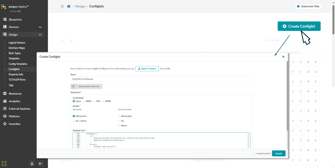
Figure 48: Apstra Interface Map for the QFX5230 Spine Nodes
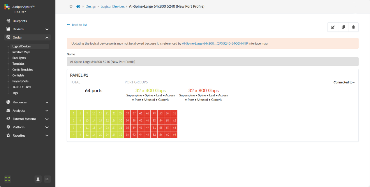
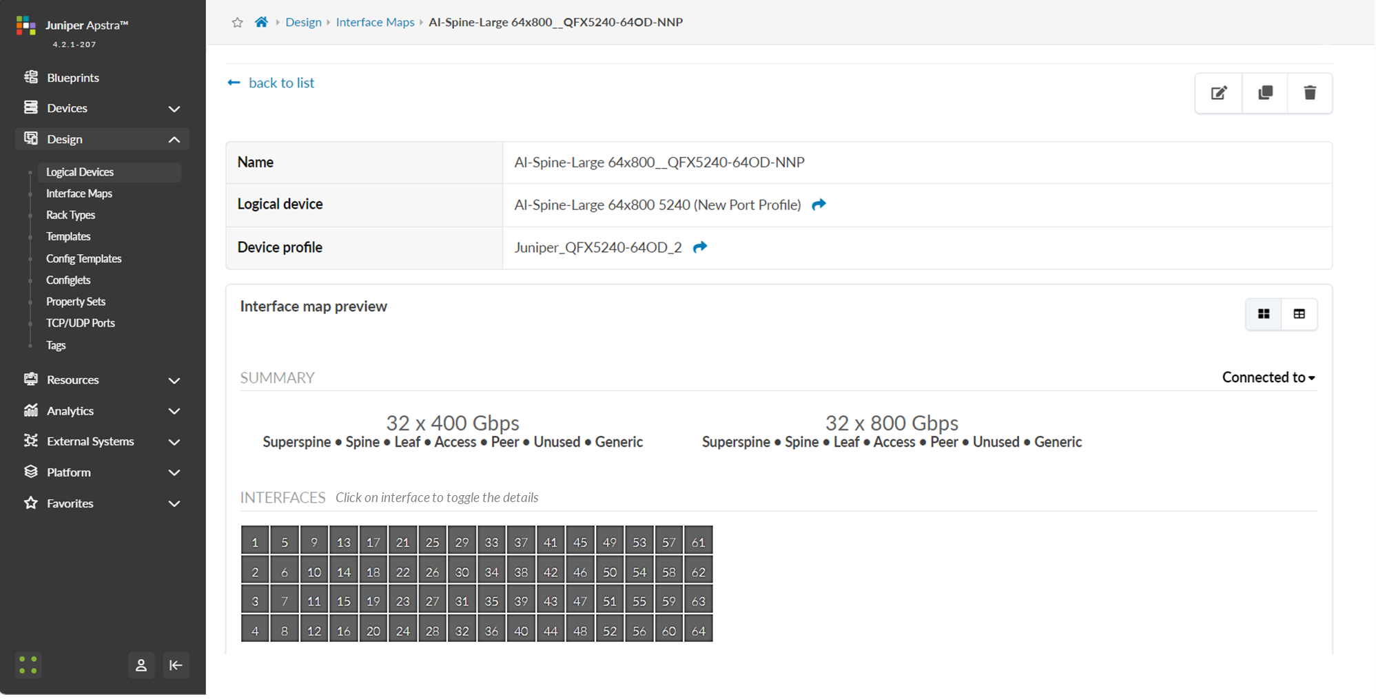
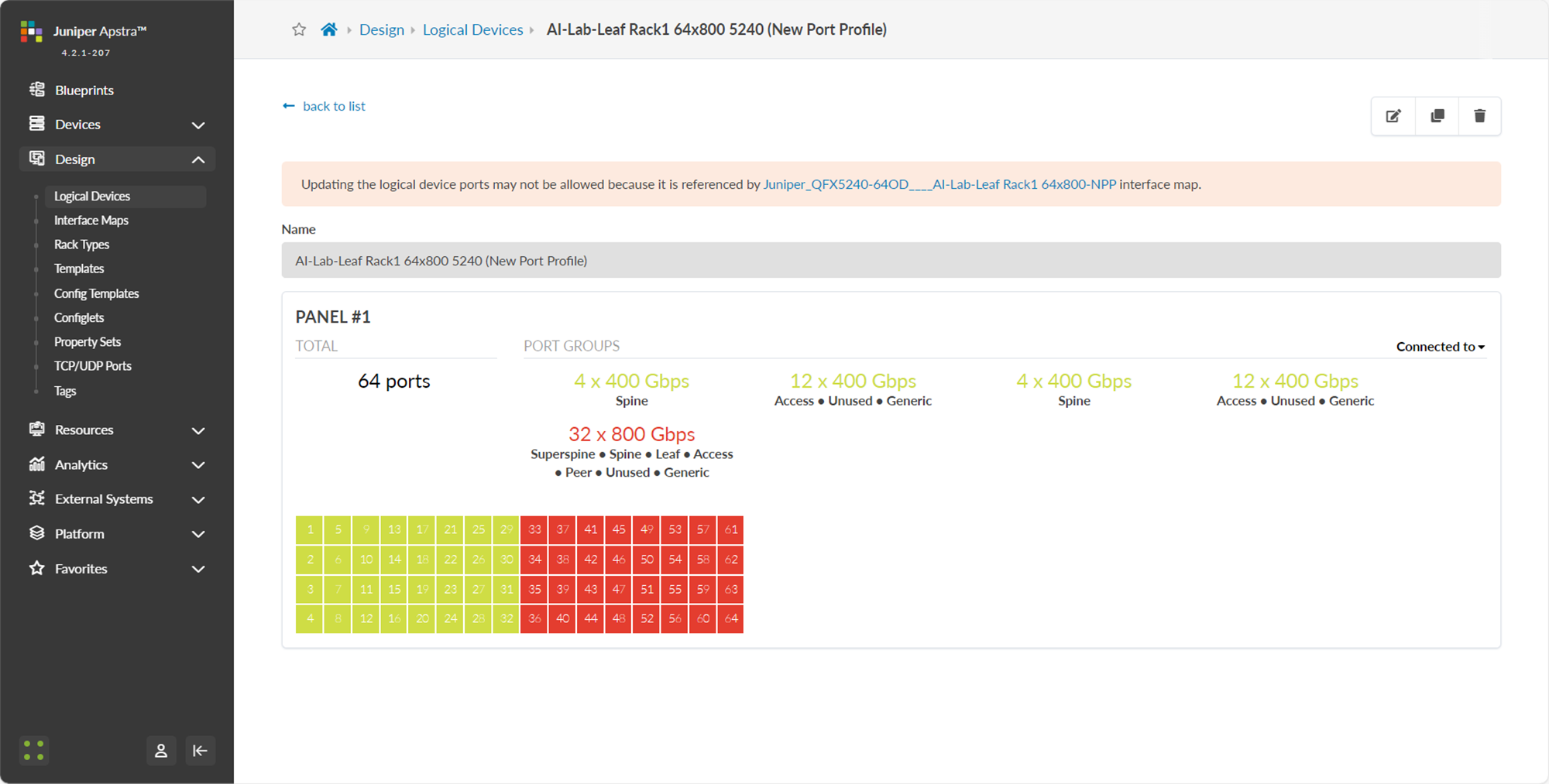
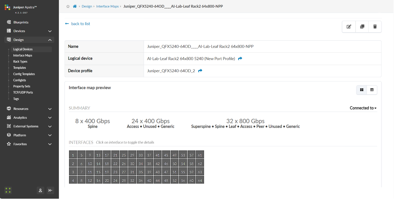
For the QFX5240 spine and leaf nodes, the Logical Device and Interface Map are shown in Figures 49-50 and 51-52 respectively.
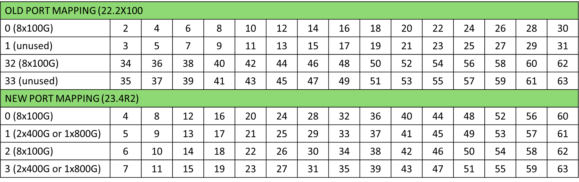
The following table shows the differences between the old and the new port mappings.
Table 25. QFX5240-64DC port mappings
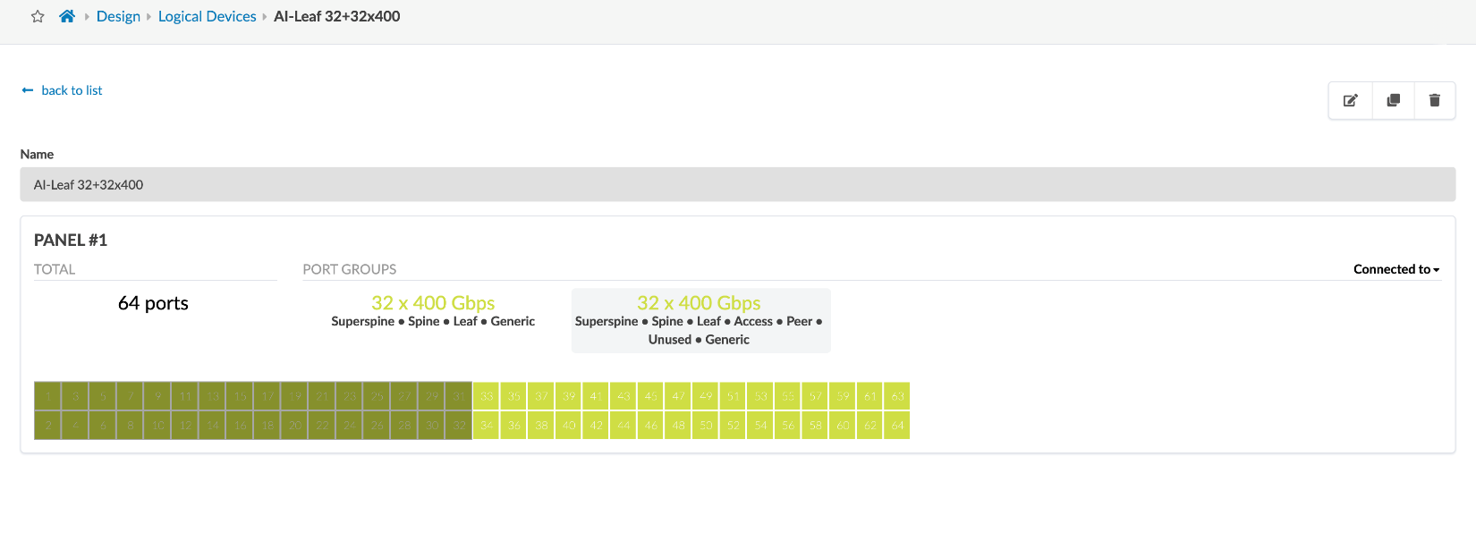
The Interface Map and Logical Devices for the QFX5240-64DC leaf and spine nodes were created following the new port mapping as shown in Figures 49-50
Figure 49: Apstra Interface Map for the QFX5240 Spine Nodes
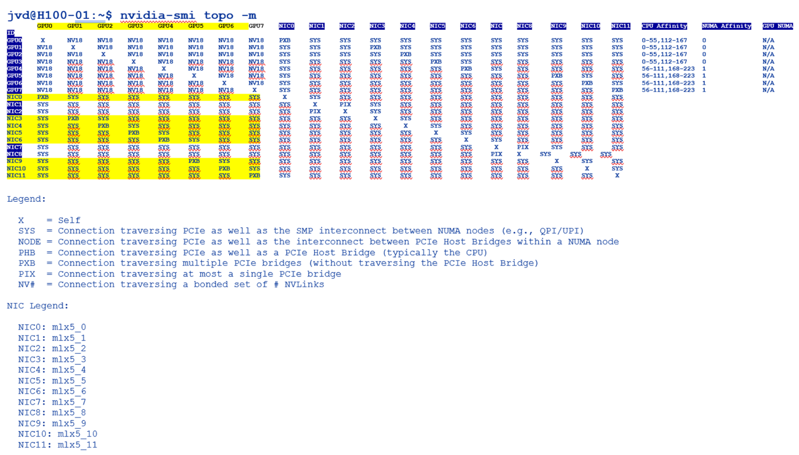
Figure 50: Apstra Logical Device for the QFX5240 Spine Nodes

Figure 51: Apstra Interface Map for the QFX5240 Leaf Nodes
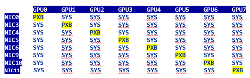
Figure 52: Apstra Logical Device for the QFX5240 Leaf Nodes
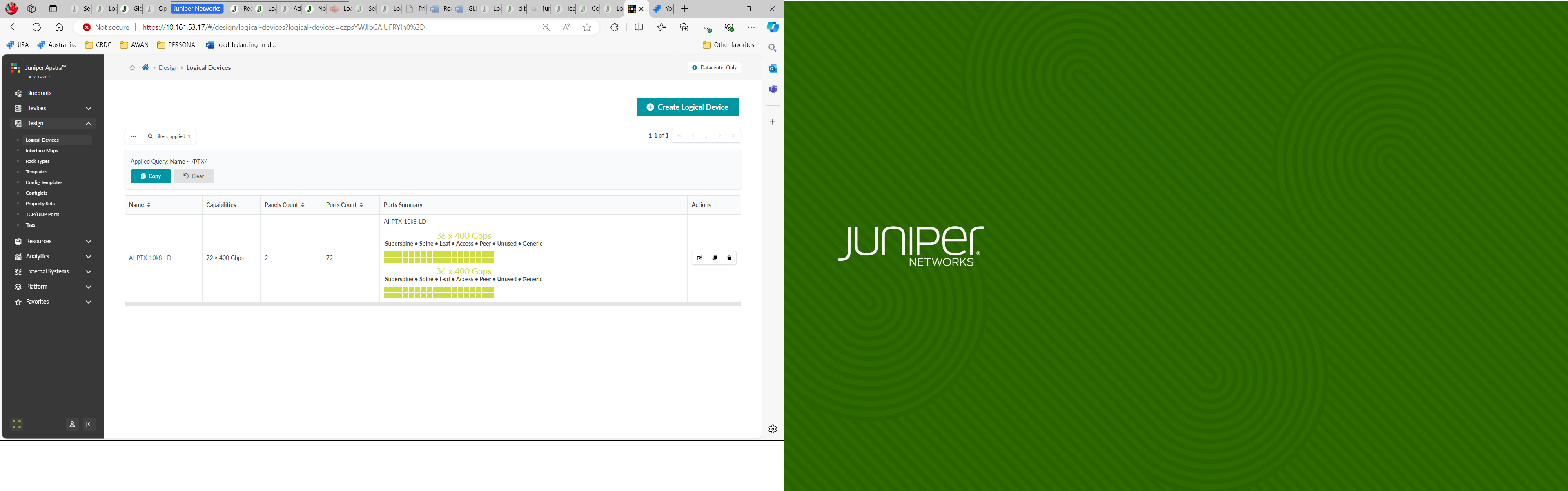
For the PTX10008 LC1201 spine nodes also tested, the Logical Device and Interface Map are shown in Figures 53-54.
Figure 53: Apstra Interface Map for the PTX Spine Nodes
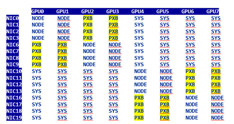
Figure 54: Apstra Logical Device for the PTX Spine Nodes
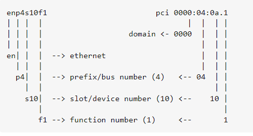
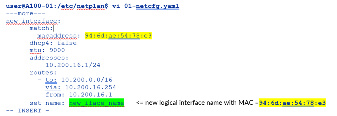
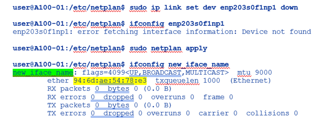
Step 2: Create Interface Map and Logical Device for the GPU servers
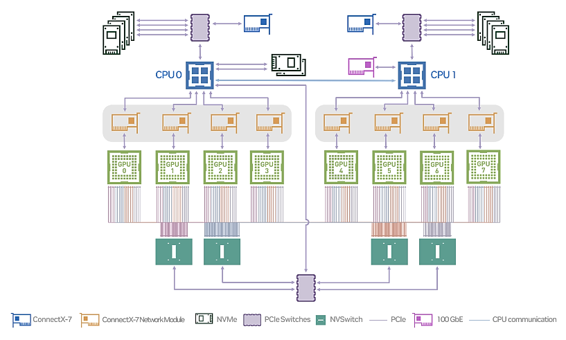
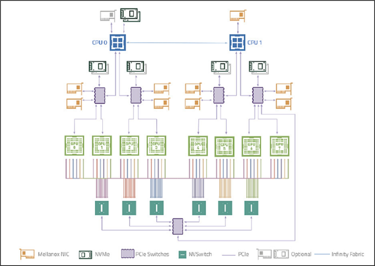
The logical Device and Interface Map for the AMD NVIDIA GPU servers are shown in Figures 55-56, respectively.
Figure 55: Apstra Interface Map for the A100 Nvidia Servers
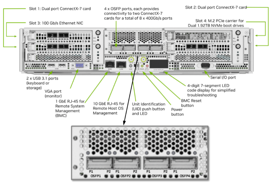
Figure 56: Apstra Interface Map for the H100 Nvidia Servers
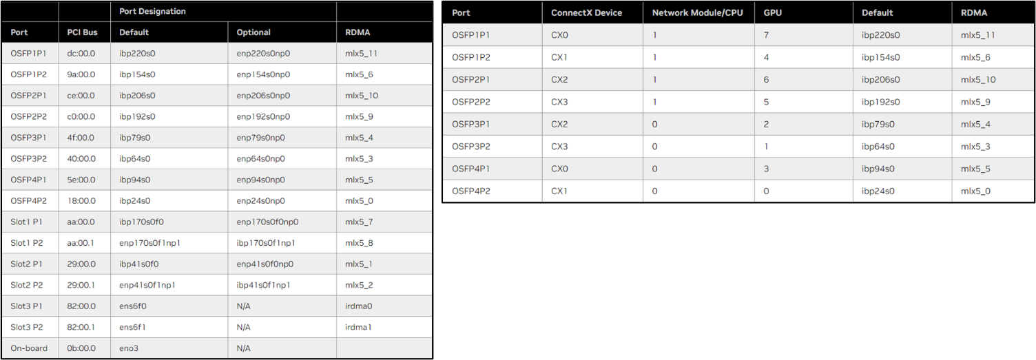
Figure 57: Logical Devices for the A100 Nvidia Servers
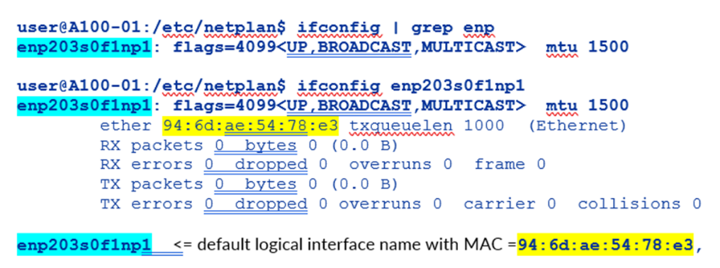
Figure 58: Logical Devices for the H100 Nvidia Servers
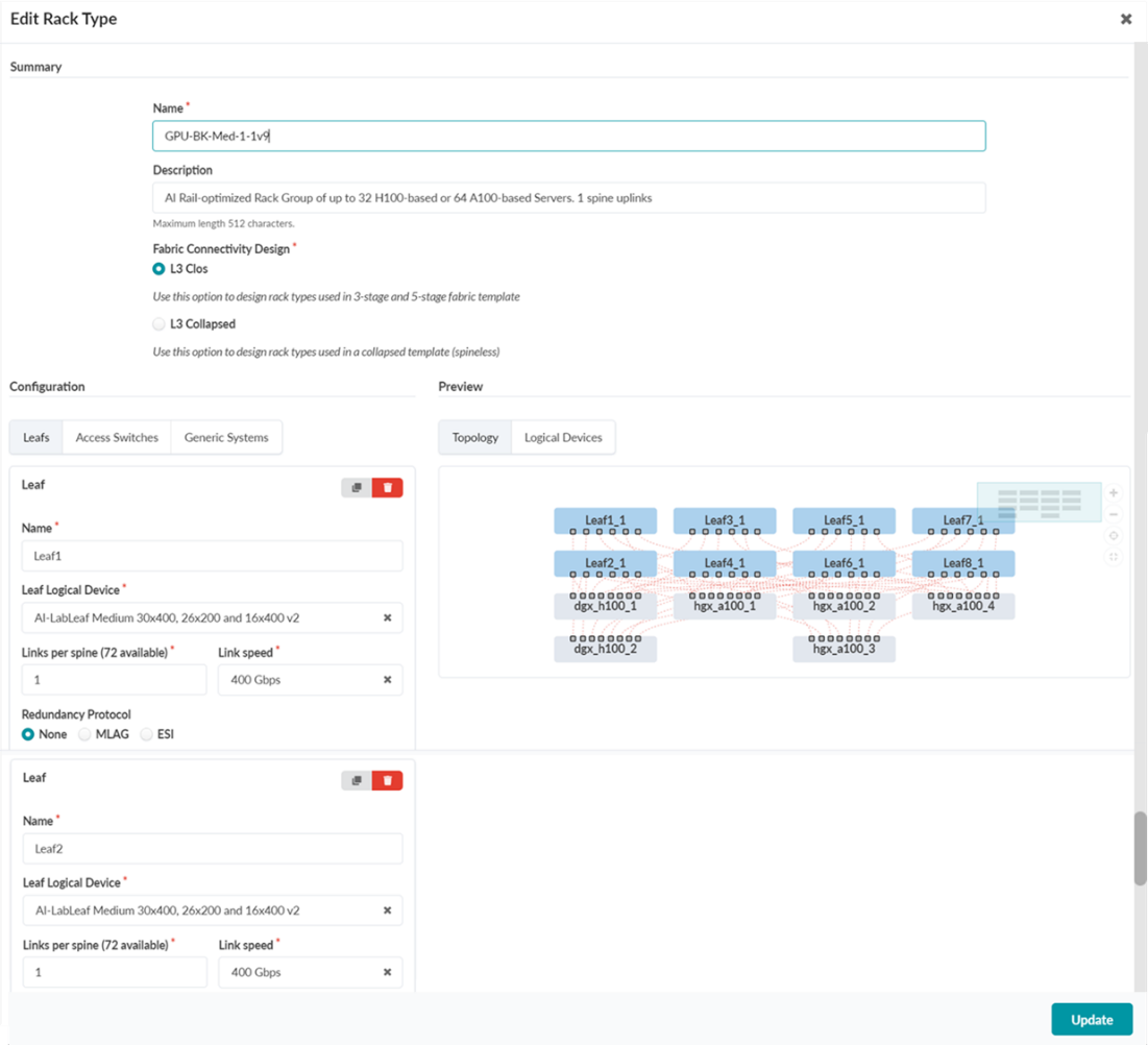
Step 3. Create Rack type for the GPU Backend Fabric
- Navigate to Design → Rack Types → Create in
Builder
NOTE: In Apstra, a Rack is technically equivalent to a stripe in the context of an AI Fabric
- Click on Create Rack Type
Figure 59: Create Rack Type in Apstra
 NOTE: You can choose between Create In Builder or Create In Designer (graphical version). We demonstrate the Create In Builder option here.
 - Provide a name and description and select L3 Clos.
Figure 60: Creating a Rack in Apstra using the Create In Builder option.
- Create the first leaf by clicking on the Add leaf button.
Figure 61: Creating Leaf nodes
Select the switch that was created and click on Manage properties of selected node(s).
Select the appropriate Logical Device.
Figure 62: Configure Leaf nodes properties
- Create additional leaf nodes by cloning the leaf created in the
previous step. Repeat until 8 leaf total have been added.
Figure 62: Creating additional leaf nodes by cloning the leaf node
Figure 63: Additional leaf nodes created
- Create the first GPU server (generic systems) by clicking on
Add generic system
Figure 64: Cloning leaf nodes.
Select the server that was created and click on Manage properties of selected node(s).
Provide a name for the server and select the appropriate Logical Device.
Figure 65: Creating and configuring first GPU server (generic system)

- Create GPU server to Leaf node
connections.
Select the Server and the first leaf and click on Manage Links.
Make sure the box “Is a Part of the Rail” is checked.
Repeat until all connections between the server and all the leaf nodes have been created.
Figure 66: Creating connections between GPU servers and leaf nodes
Figure 67: Creating connections between GPU servers and leaf nodes
- Create additional servers by cloning the server created in the
previous step. Repeat until 8 leaf total have been added. All connections will be
cloned.
Figure 68: Creating additional servers
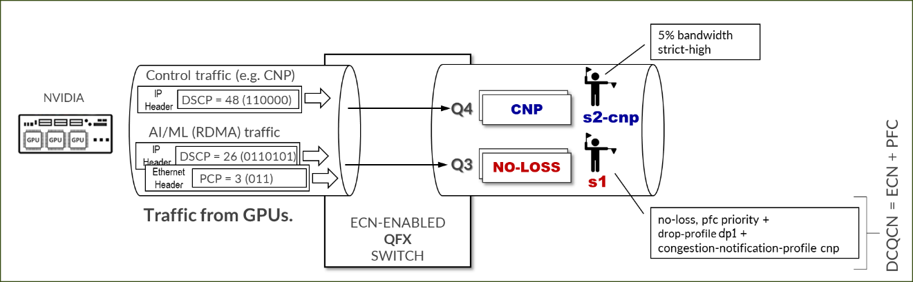
Figure 69: Creating additional servers
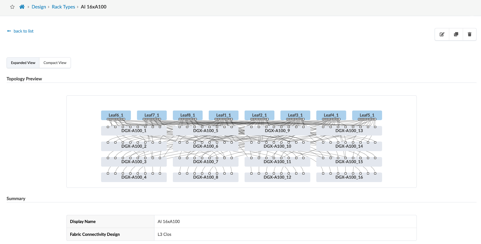
- Verify the Rack has been created correctly:
Figure 70: Creating connections between GPU servers and leaf nodes
Figure 71: Creating connections between GPU servers and leaf nodes

Figure 72: Creating connections between GPU servers and leaf nodes
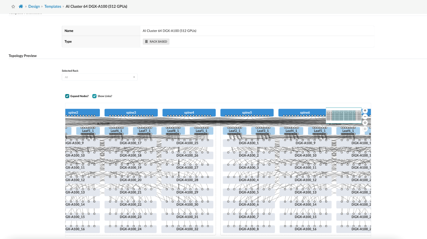
Figure 73: Creating connections between GPU servers and leaf nodes
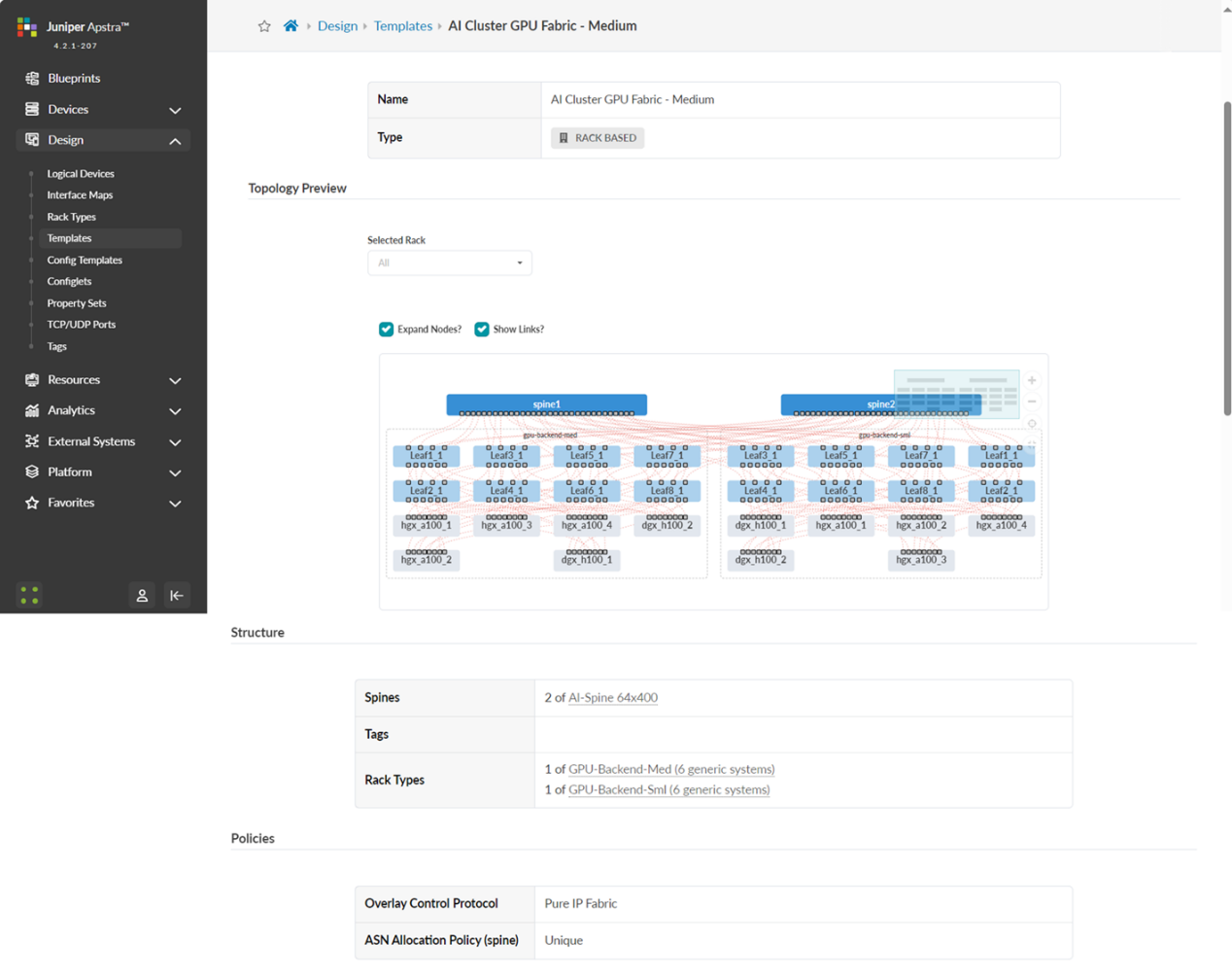
Step 4: Create a Template.
Navigate to Design -> Templates -> Create Template
- Click on Create Template
Figure 74: Create Apstra Template
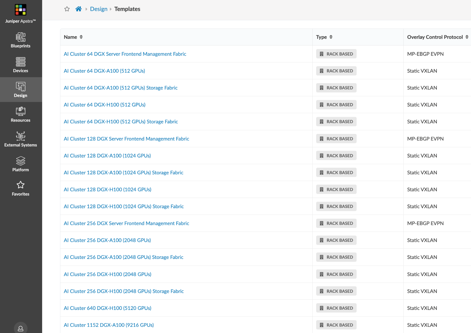
 NOTE: You can choose between Create Template or Create AI Cluster Template (Select from pre-existing designs based on required number of GPUs per stripe, and number of stripes.). We will demonstrate the Create Template option here.
 - Enter the name of the template, and select Type RACK BASED,
policies ASN allocation Unique, and Overlay Pure IP Fabric.
Figure 75: Creating a Template in Apstra - Parameters
- Scroll down and select the Rack type and Spine logical device created in previous steps, set the number of Racks (which is equivalent to saying number of stripes), and the number of spines. Click on create when ready, as shown in Figure 75.
Figure 76: Creating a Template in Apstra - Structure
Figure 77: Verifying new template creation
Step 5. Create the GPU Backend Fabric Blueprint
- Navigate to the Blueprints section and click
on Create Blueprint, as shown in Figure 78.
Figure 78: Creating a Blueprint in Apstra
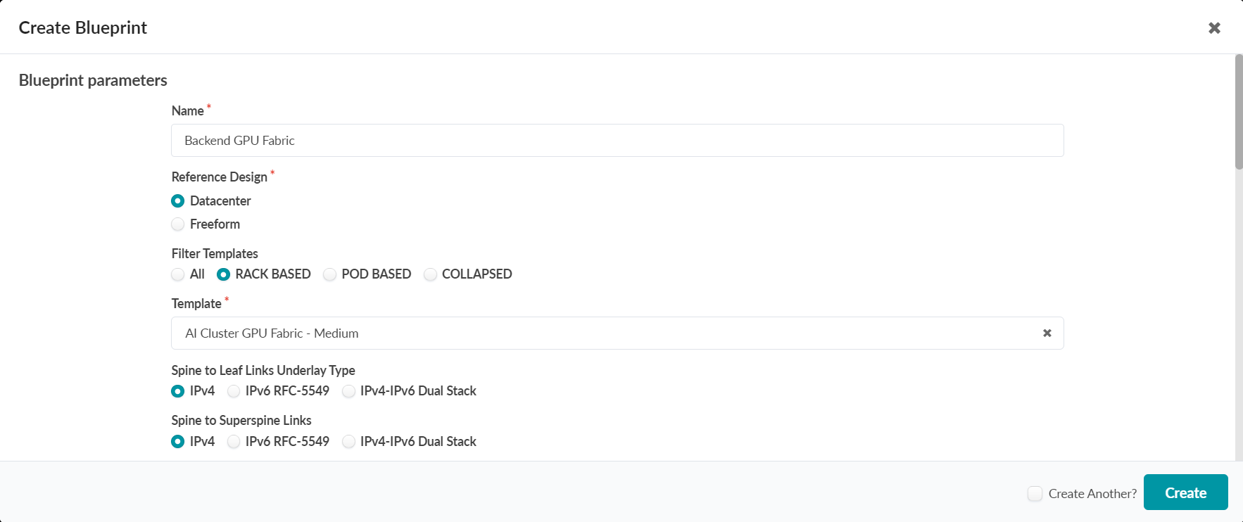
- Provide a name for the new blueprint, select data center as the reference design, and select Rack-based. Then select the template that was created in the previous step, which will include the two rack types that were created before.
Figure 79: New Blueprint Attributes in Apstra
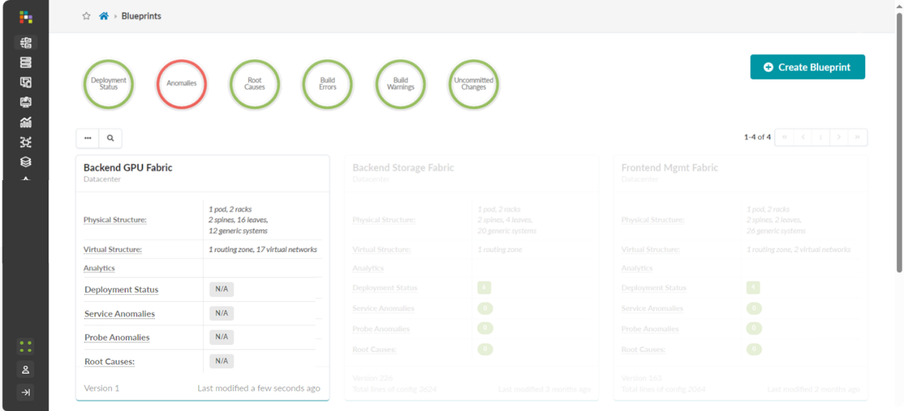
Once the blueprint is successfully initiated by Apstra, it will be included in the Blueprint dashboard as shown below.
Figure 80: New Blueprint Added to Blueprint Dashboard
Notice that the Deployment Status, Service Anomalies, Probe Anomalies and Root Causes all shown as N/A. This is because you will need to complete additional steps that inlcudes mapping the different roles in the blueprint to the physical devices, defining which interfaces will be used, etc.
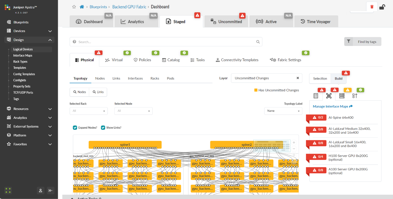
When you click on the blueprint name and enter the blueprint dashboard it will indicate that the blueprint has not been deployed yet.
Figure 81: New Blueprint’s dashboard
The Staged view as depicted in Figure 82 shows that the topology is correct, but attributes such as mandatory ASNs and loopback addressing for the spines and the leaf nodes, and the spine to leaf links addressing must be provided by the user.
Figure 82: Undeployed Blueprint Dashboard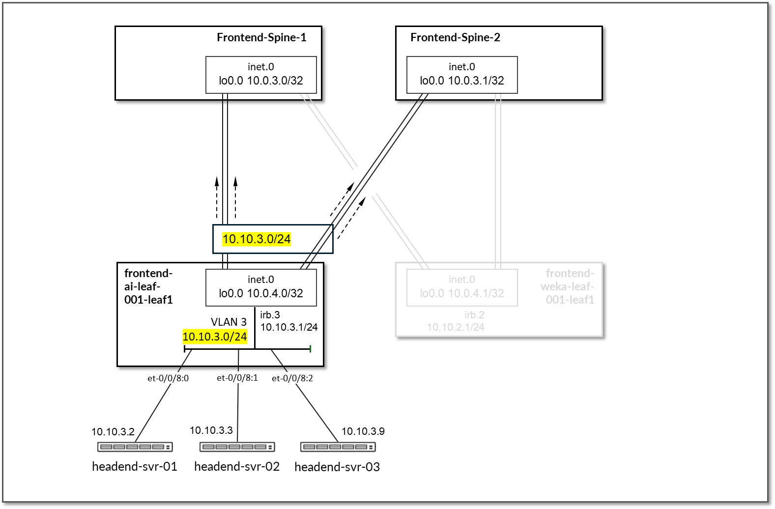
You will need to edit each one of these attributes and select from predefined pools of addresses and ASNs, as shown in the example on Figure 83, to fix this issue.
Figure 83: Selecting ASN Pool for Spine Nodes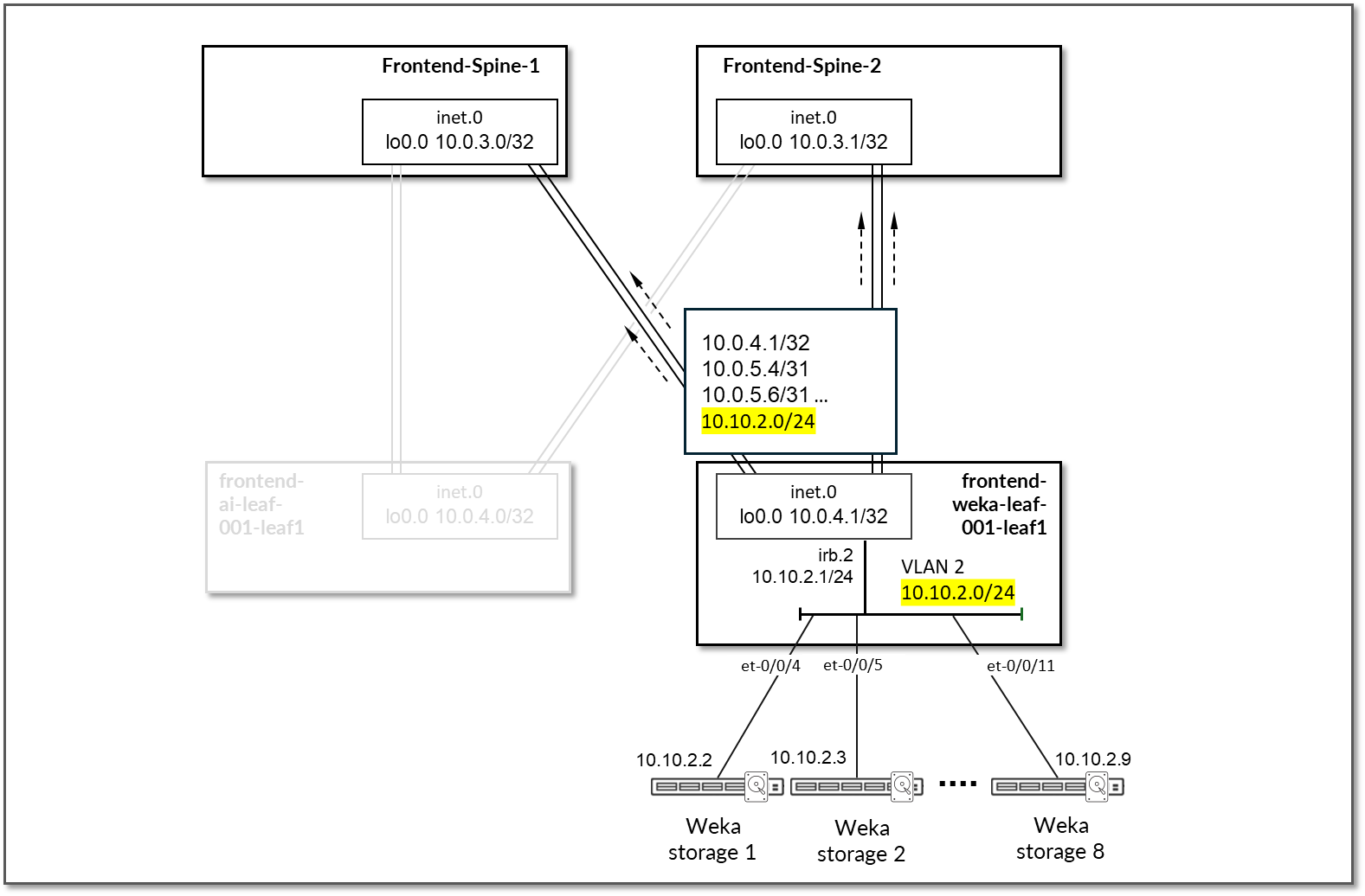
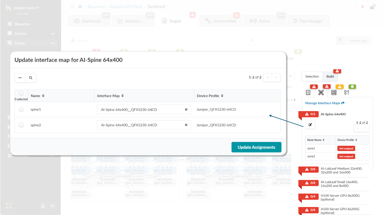
You will also need to select Interface Maps for each devices’ role and along with assignment of system IDs as shown in Figures 84-85.
Figure 84: Mapping Interface Maps to Spine Nodes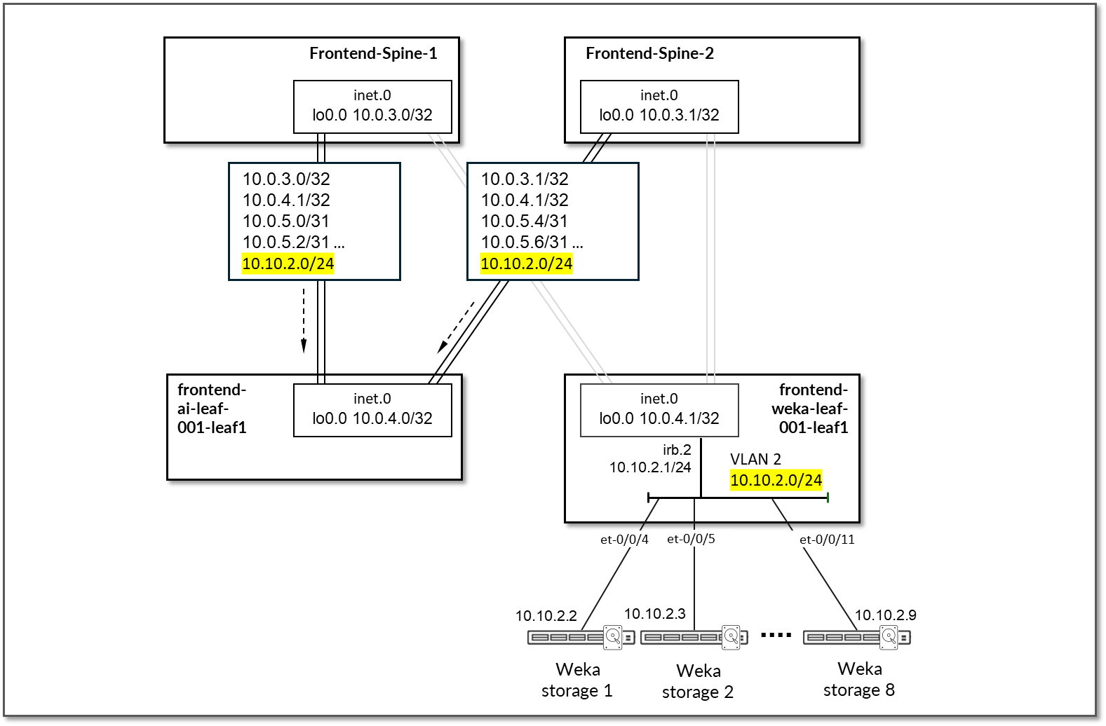
Figure 85: Mapping Spine Nodes to Physical Devices (System
IDs)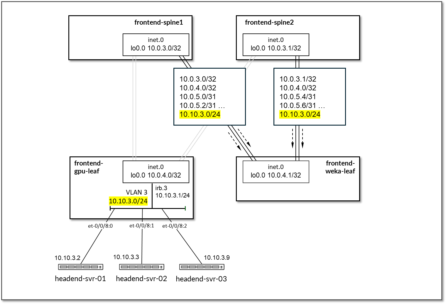
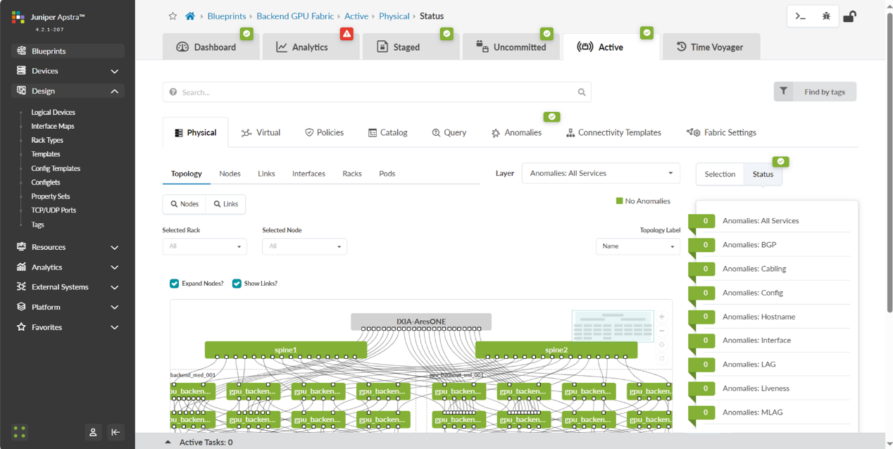
Once all these steps are completed, you can commit all the changes and Apstra will generate and push all the necessary vendor-specific configuration to the nodes. Once this has been completed, you should be able to view an active blueprint that represents the successfully deployed fabric as shown in Figure 86.
Figure 86: Mapping Spine Nodes to Physical Devices 2 (System IDs)
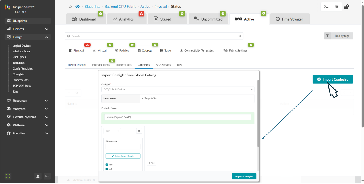
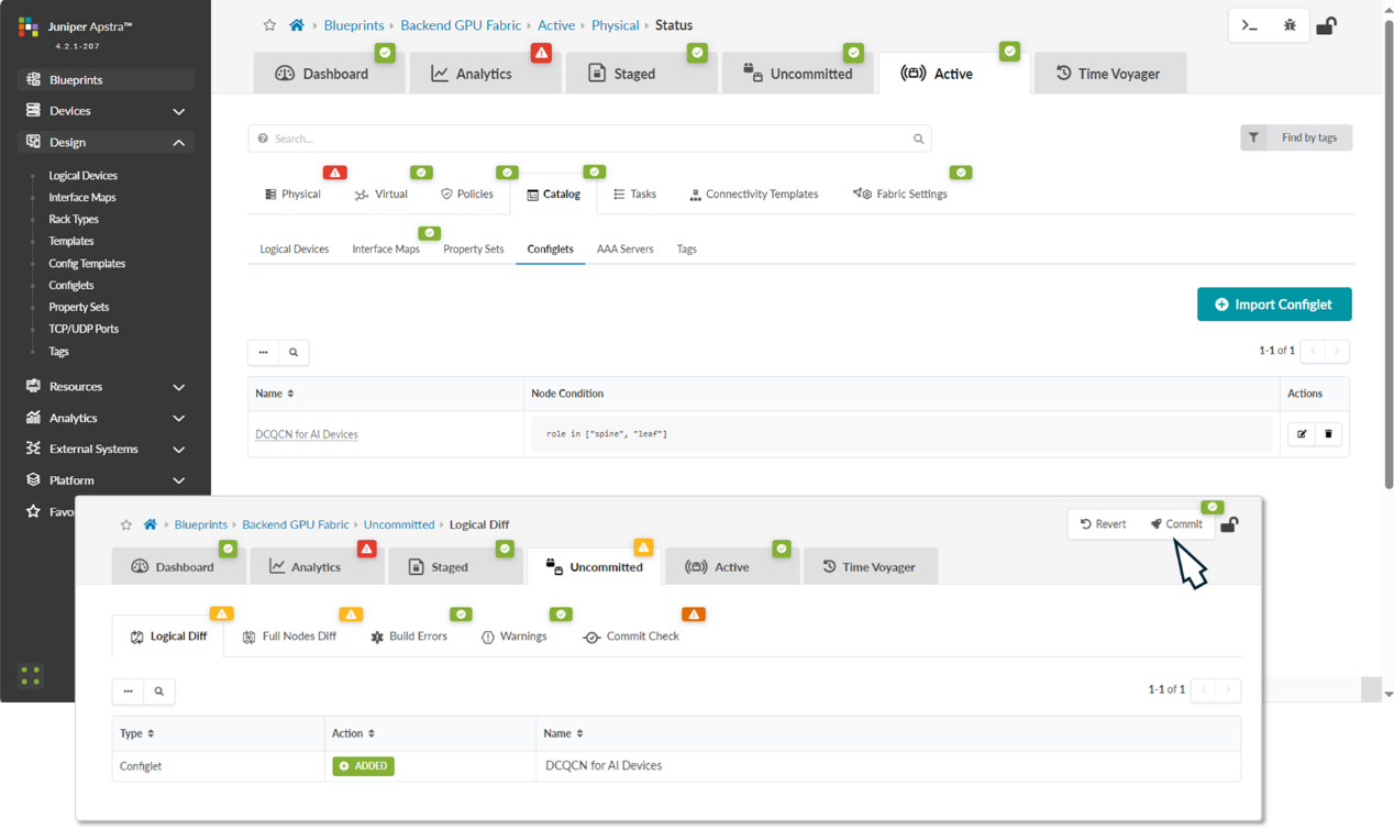
Step 6: Create Configlets for DCQCN and DLB.
In the Apstra version used for this JVD, features such as ECN, PFC (DCQCN), and DLB are not natively available. Therefore, Apstra configlets should be used to add these features to the configurations before they are deployed to the fabric devices.
The configlet used for the DCQCN and DLB features on the QFX leaf nodes is as follows:
-
/* DLB configuration for Thor NIC2 Adapter */

hash-key {

    family inet {

        layer-3;

        layer-4;

    }

}

enhanced-hash-key {

    ecmp-dlb {

        flowlet {

            inactivity-interval 128;

            flowset-table-size 2048;

        }

        ether-type {

            ipv4;

            ipv6;

        }

        sampling-rate 1000000;

    }

}

protocols {

    bgp {

        global-load-balancing {

            load-balancer-only;

        }

    }

}

/* DCQCN configuration */

classifiers {

    dscp mydscp {

        forwarding-class CNP {

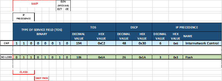
            loss-priority low code-points 110000;

        }

        forwarding-class NO-LOSS {

            loss-priority low code-points 011010;

        }

    }

}

drop-profiles {

    dp1 {

        interpolate {

            fill-level [ 55 90 ];

            drop-probability [ 0 100 ];

        }

    }

}

    shared-buffer {

        ingress {

       buffer-partition lossless {

          percent 66;

          dynamic-threshold 10;

       }

       buffer-partition lossless-headroom {

          percent 24;

       }

       buffer-partition lossy {

          percent 10;

       }

      }

      egress {

        buffer-partition lossless {

           percent 66;

        }

        buffer-partition lossy {

           percent 10;

        }

      }

    }

forwarding-classes {

    class CNP queue-num 3;

    class NO-LOSS queue-num 4 no-loss pfc-priority 3;

}

congestion-notification-profile {

    cnp {

        input {

            dscp {

                code-point 011010 {

                    pfc;

                }

            }

        }

        output {

            ieee-802.1 {

                code-point 011 {

                    flow-control-queue 4;

                }

            }

        }

    }

}

interfaces {

    et-* {

        congestion-notification-profile cnp;

        scheduler-map sm1;

        unit * {

            classifiers {

                dscp mydscp;

            }

        }

    }

}

scheduler-maps {

    sm1 {

        forwarding-class CNP scheduler s2-cnp;

        forwarding-class NO-LOSS scheduler s1;

    }

}

schedulers {

    s1 {

        drop-profile-map loss-priority any protocol any drop-profile dp1;

        explicit-congestion-notification;

    }

    s2-cnp {

        transmit-rate percent 5;

        priority strict-high;

    }

}
The configlet used for the DCQCN and DLB features on the QFX spine nodes is as follows:
-
/* DLB configuration */

hash-key {

    family inet {

        layer-3;

        layer-4;

    }

}

enhanced-hash-key {

    ecmp-dlb {

        flowlet {

            inactivity-interval 128;

            flowset-table-size 2048;

        }

        ether-type {

            ipv4;

            ipv6;

        }

        sampling-rate 1000000;

    }

}

protocols {

    bgp {

        global-load-balancing {

            helper-only;

        }

    }

}

/* DCQCN configuration */

class-of-service {

    classifiers {

        dscp mydscp {

            forwarding-class CNP {

                loss-priority low code-points 110000;

            }

            forwarding-class NO-LOSS {

                loss-priority low code-points 011010;

            }

        }

    }

    drop-profiles {

        dp1 {

            interpolate {

                fill-level [ 55 90 ];

                drop-probability [ 0 100 ];

            }

        }

    }

    shared-buffer {

        ingress {

       buffer-partition lossless {

          percent 66;

          dynamic-threshold 10;

       }

       buffer-partition lossless-headroom {

          percent 24;

       }

       buffer-partition lossy {

          percent 10;

       }

      }

      egress {

        buffer-partition lossless {

           percent 66;

        }

        buffer-partition lossy {

           percent 10;

        }

      }

    }

    forwarding-classes {

        class CNP queue-num 3;

        class NO-LOSS queue-num 4 no-loss pfc-priority 3;

    }

    congestion-notification-profile {

        cnp {

            input {

                dscp {

                    code-point 011010 {

                        pfc;

                    }

                }

            }

            output {

                ieee-802.1 {

                    code-point 011 {

                        flow-control-queue 4;

                    }

                }

            }

        }

    }

    interfaces {

        et-* {

            congestion-notification-profile cnp;

            scheduler-map sm1;

            unit * {

                classifiers {

                    dscp mydscp;

                }

            }

        }

    }

    scheduler-maps {

        sm1 {

            forwarding-class CNP scheduler s2-cnp;

            forwarding-class NO-LOSS scheduler s1;

        }

    }

    schedulers {

        s1 {

            drop-profile-map loss-priority any protocol any drop-profile dp1;

            explicit-congestion-notification;

        }

        s2-cnp {

            transmit-rate percent 5;

            priority strict-high;

        }

    }

}
The configuration used for the DCQCN features on the PTX10008 as spine devices is as follows:
-
/* ALB configuration */

policy-options {

    policy-statement ALB-TEST {

        term 1 {

            from {

                route-filter 10.200.1.0/24 exact;

            }

            then {

                load-balance adaptive;

            }

        }

    }

}

routing-options {

    forwarding-table {

        export ALB-TEST;

    }

}

chassis {

    ecmp-alb {

        tolerance 20;

    }

    interoperability express5-enhanced;

}

/* DCQCN configuration */

classifiers {

    dscp rdma-dscp {

        forwarding-class rdma-cnp {

            loss-priority low code-points 110000;

        }

        forwarding-class rdma-data {

            loss-priority low code-points 011010;

        }

    }

}

drop-profiles {

    dp-ecn {

        fill-level 3 drop-probability 100;

    }

}

forwarding-classes {

    class network-control queue-num 3;

    class other queue-num 1;

    class rdma-cnp queue-num 0;

    class rdma-data queue-num 2 no-loss;

}

monitoring-profile {

    myMon {

        export-filters qall {

            peak-queue-length {

                percent 100;

            }

            queue [ 3 1 2 ];

        }

    }

}

interfaces {

    et-* {

        scheduler-map sched-map-aiml;

        monitoring-profile myMon;

        unit * {

            classifiers {

                dscp rdma-dscp;

            }

        }

    }

}

scheduler-maps {

    sched-map-aiml {

        forwarding-class network-control scheduler sched-nc;

        forwarding-class other scheduler sched-other;

        forwarding-class rdma-cnp scheduler sched-rdma-cnp;

        forwarding-class rdma-data scheduler sched-rdma-data;

    }

}

options {

    hierarchical-scheduler-disable;

}

schedulers {

    sched-nc {

        transmit-rate percent 1;

        priority medium-high;

    }

    sched-other {

        priority low;

    }

    sched-rdma-cnp {

        transmit-rate percent 1;

        priority high;

    }

    sched-rdma-data {

        transmit-rate percent 97;

        buffer-size temporal 400;

        priority medium-high;

        drop-profile-map loss-priority any protocol any drop-profile dp-ecn;

        explicit-congestion-notification;

        ecn-enhanced {

            head-marking;

        }

    }

}
To create these configlets:
- Navigate to Design -> Configlets -> Create Configlet and click on Create configlet.
- Provide a name for the configlet, select the operating system, vendor and configuration mode and paste the above configuration snippet on the template text box as shown below:
Figure 87: DCQCN Configlet Creation in Apstra