Calculating the number of leaf and spine nodes, Servers, and GPUs in a rail optimized architecture
The number of leaf nodes in a single stripe in a rail optimized architecture is defined by the number of GPUs per server (number of rails). Each NVIDIA DGX H100 GPU server includes 8 NVIDIA H100 Tensor core GPUs. Therefore, a single stripe includes 8 leaf nodes (8 rails).
Number of leaf nodes = number of GPUs per server = 8
The maximum number of servers supported in a single stripe (N1) is defined by the number of available ports on the Leaf node which depends on the switches model.
The total bandwidth between the GPU servers and leaf nodes must match the total bandwidth between leaf and spine nodes to maintain a 1:1 subscription ratio.
Assuming all the interfaces on the leaf node operate at the same speed, half of the interfaces will be used to connect to the GPU servers, and the other half to connect to the spines. Thus, the maximum number of servers in a stripe is calculated as half the number of available ports on each leaf node. Some examples are included in Table 14.
Figure 14. Number of uplinks and downlinks for 1:1 subscription
factor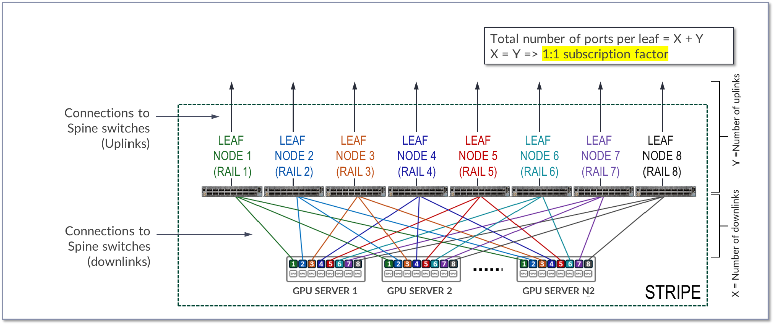
I the diagram X represents the number of downlink (links between leaf nodes and the GPU servers), while Y represents the number of uplinks (links between the leaf nodes and the spine nodes). To allow for a 1:1 subscription factor, X must be equal to Y.
The number of available ports on each leaf node is equal to X + Y or 2 * X.
Because all servers in a stripe have one port connected to every leaf in the stripe the maximum number of servers in the stripe (N1) is equal X.
N1 (maximum number of servers per stripe) = number of available ports ÷ 2
The maximum number of GPUs in the stripe is calculated by simply multiplying by the number of GPUs per server.
N2 (maximum number of GPUs) = N1 (maximum number of servers per stripe) * 8
The total number of available ports is dependent on the switch model used for the leaf node. Table 9 shows some examples.
Table 9: Maximum number of GPUs supported per stripe
|
Leaf Node QFX switch Model |
total number of available 400 GE ports per switch |
Maximum number of servers supported per stripe for 1:1 Subscription (N1) |
GPUs per server |
Maximum number of GPUs supported per stripe (N2) |
|---|---|---|---|---|
| QFX5220-32CD | 32 | 32 ÷ 2 = 16 | 8 | 16 servers x 8 GPUs/server = 128 GPUs |
| QFX5230-64CD | 64 | 64 ÷ 2 = 32 | 8 | 32 servers x 8 GPUs/server = 256 GPUs |
| QFX5240-64OD | 128 | 128 ÷ 2 = 64 | 8 | 64 servers x 8 GPUs/server = 512 GPUs |
- QFX5220-32CD switches provide 32 x 400 GE ports (16 will be used to connect to the servers and 16 will be used to connect to the spine nodes)
- QFX5230-64CD switches provide up to 64 x 400 GE ports (32 will be used to connect to the servers and 32 will be used to connect to the spine nodes).
- QFX5240-64OD switches provide up to 128 x 400 GE ports (64 will be used to connect to the servers and 64 will be used to connect to the spine nodes).
- To achieve larger scales, multiple stripes (N3) can be connected using a set of Spine nodes (N4), as shown in Figure 10.
Figure 10: Multiple Stripes connected across Spine nodes.
.png)
The number of stripes required is calculated based on the number of GPUs required, and the number of GPUs supported per stripe.
For example, assume that the required number of GPUs (GPUs) is 16,000 and the fabric is using QFX5240-64OD as leaf nodes.
The number of available 400G ports is 128, which means that:
- the maximum number of servers per stripe (N1) = 64
- the maximum number of GPUs per stripe (N2) = 512
To number of stripes (N3) required is calculated by diving the number of GPUs required, and the number of GPUs per stripe as shown:
N 3 (number of stripes) = GPUs/ N 2 (maximum number of GPUs per stripe) = 16000/256 ≈ 64 stripes
- with 64 stripes & 256 servers per stripe the cluster can provide 16,384 GPUs.
- with N2 = 72 & N1 servers = 32 the cluster can provide 18432 GPUs.
- With 64 stripes & 256 servers per stripe the cluster can provide 16,384 GPUs.
Knowing the number of stripes required (N 3) and the number of uplinks ports per leaf node (Y) you can calculate how many spine nodes are required.
Remember X = Y = N1
First the total number of leaf nodes can be calculated by multiplying the number of stripes required by 8 (number of leaf nodes per stripe).
Total number of leaf nodes = N3 x 8 = 64 x 8 = 512
Then the total number of uplinks can be obtained multiplying the number of uplinks per leaf node (N1), and the total number of leaf nodes.
Total number of uplinks = N1 x N3 = 64 x 512 = 32768
The number of spines required (N4 ) can then be determined by dividing the total number of uplinks by the number of available ports on each spine node, which as for the leaf nodes, depends on the switch model used for the spine role.
Number of spines required (N4) = 32768 / number of available ports on each spine node
For example, if the spine nodes are QFX5240, the number of available ports on each spine node is 128.
Table 8: Number of spines nodes for two stripes.
|
Spine Node QFX switch Model |
Maximum number of 400 GE interfaces per switch | Number of spines required (N4) with 64 stripes |
|---|---|---|
| QFX5240-64OD | 128 | 32768 ÷ 128 = 256 |
| PTX10008 | 288 | 32768 ÷ 288 ~ 128 |