Network Connectivity Details (Reference Examples)
This section provides detailed examples for each fabric, as reference. It describes the IP connectivity across the common Frontend, and Storage Backend fabrics, and the GPU Backend fabric in Cluster 2.
Regardless of whether you are using Apstra with or without Terraform automation, the IP address Pools, ASN Pools, and interface addresses are automatically assigned and configured with little interaction from the administrator unless desired.
Notice that all the addresses shown in this section represent the IP addressing schema used in the Juniper lab to validate the design.
Frontend Network Connectivity
The Frontend fabric consists of two spine nodes (QFX5130-32CD) and two leaf nodes (QFX5130-32CD), where one leaf node is used to connect the GPU servers and Headend servers (frontend-leaf1), and one is used to connect the Storage devices (frontend-leaf2).
IP addressing
The Frontend fabric is designed as a Layer 3 IP Fabric, with two 400GE links between each frontend-leaf# node and each frontend-spine# node as shown in Figure 99. These links are configured with /31 IP addresses, as shown in Table 26.
Figure 99: Frontend Spine to Leaf Nodes Connectivity
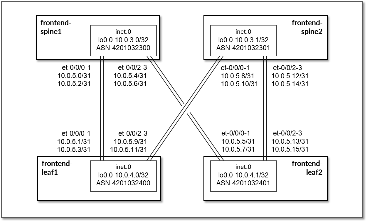
Table 26: Frontend Interface Addresses
| Spine node | Leaf node | Spine IP address | Leaf IP address |
|---|---|---|---|
| frontend-spine1 | frontend-leaf1 |
10.0.5.0/31 10.0.5.2/31 |
10.0.5.1/31 10.0.5.3/31 |
| frontend-spine1 | frontend-leaf2 |
10.0.5.4/31 10.0.5.6/31 |
10.0.5.5/31 10.0.5.7/31 |
| frontend-spine2 | frontend-leaf1 |
10.0.5.8/31 10.0.5.10/31 |
10.0.5.9/31 10.0.5.11/31 |
| frontend-spine2 | frontend-leaf2 |
10.0.5.12/31 10.0.5.14/31 |
10.0.5.13/31 10.0.5.15/31 |
Table 27: Frontend Loopback Addresses
| Device | Loopback interface address |
|---|---|
| frontend-spine1 | 10.0.3.0/32 |
| frontend-spine2 | 10.0.3.1/32 |
| frontend-leaf1 | 10.0.1.0/32 |
| frontend-leaf2 | 10.0.1.1/32 |
The MI300X GPU Servers and Headend servers are all connected to frontend-leaf1 as shown in Figure 100
Figure 100: Frontend Leaf Nodes to GPU Servers Connectivity
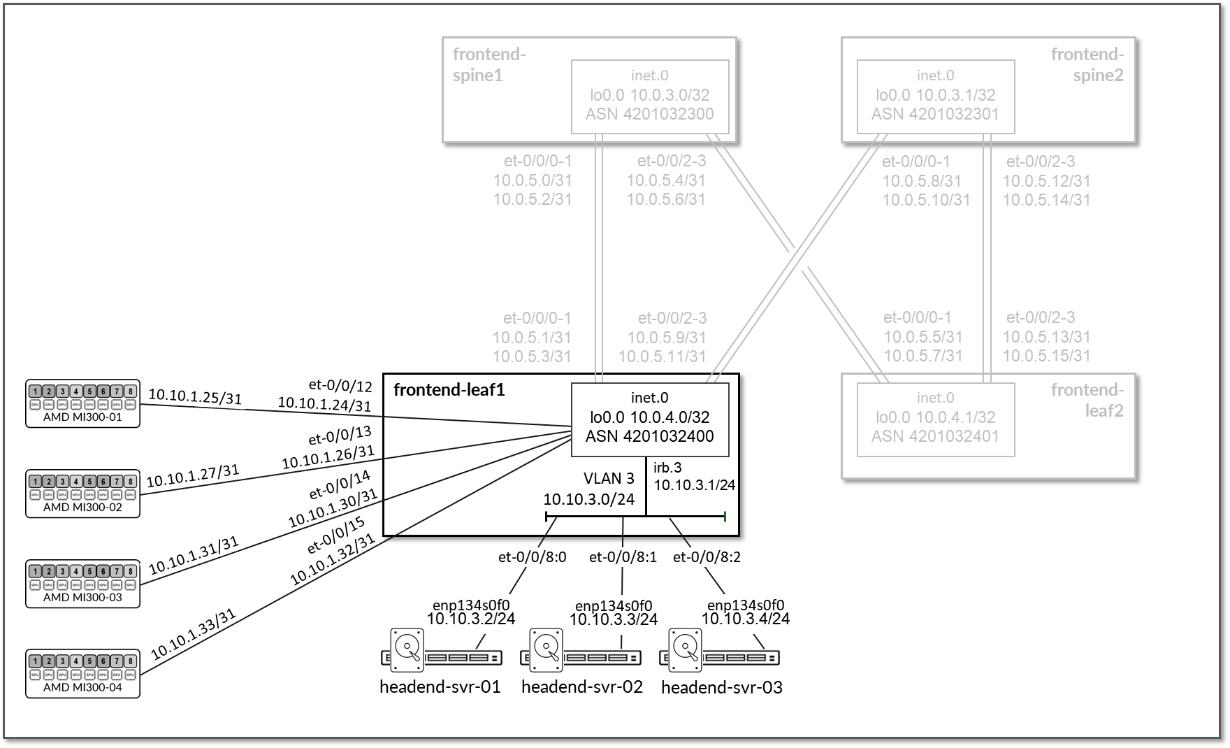
The links between these servers and frontend-leaf1 are configured with /31 subnets from the 10.0.5.0/24 subnet.
The links between the Headend servers and frontend-leaf1 do not have IP addresses assigned on the leaf node side. Layer 3 connectivity to the fabric is provided via an irb interface with address 10.10.3.1/24. The headend servers are configured with addresses out of 10.10.3.0/24 and use 10.10.3.1 as their default gateway. This is shown in table 28.
Table 28: Frontend Leaf Nodes to GPU Servers Interfaces Addresses
| GPU Server | Leaf node | GPU Server IP address | Leaf IP address |
|---|---|---|---|
| MI300X GPU Server 1 | frontend-leaf1 | 10.10.1.25/31 | 10.10.1.24/31 |
| MI300X GPU Server 2 | 10.10.1.27/31 | 10.10.1.26/31 | |
| MI300X GPU Server 3 | 10.10.1.31/31 | 10.10.1.30/31 | |
| MI300X GPU Server 4 | 10.10.1.33/31 | 10.10.1.32/31 | |
| Headend Server 1 | 10.10.3.2/24 | 10.10.3.1/24 (irb.3) | |
| Headend Server 1 | 10.10.3.3/24 | ||
| Headend Server 1 | 10.10.3.4/24 |
Routing information
EBGP is configured between the IP addresses assigned to the spine-leaf links. There are two EBGP sessions between each frontend-leaf# node and each frontend-spine#
Table 29: Frontend Sessions
| Spine node | Leaf node | Spine | Leaf ASN | Spine IP address | Leaf IP address |
|---|---|---|---|---|---|
| frontend-spine1 | frontend-leaf1 | 4201032300 | 4201032400 |
10.0.5.0/31 10.0.5.2/31 |
10.0.5.1/31 10.0.5.3/31 |
| frontend-spine1 | frontend-leaf2 | 4201032401 |
10.0.5.4/31 10.0.5.6/31 |
10.0.5.4/31 10.0.5.7/31 |
|
| frontend-spine2 | frontend-leaf1 | 4201032301 | 4201032400 |
10.0.5.8/31 10.0.5.10/31 |
10.0.5.9/31 10.0.5.11/31 |
| frontend-spine2 | frontend-leaf2 | 4201032401 |
10.0.5.12/31 10.0.5.14/31 |
10.0.5.13/31 10.0.5.15/31 |
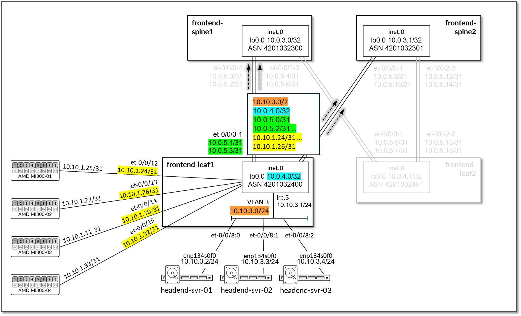
On the frontend-leaf1 node, BGP policies are configured by Apstra to advertise the following routes to the spine nodes:
- frontend-leaf1 node loopback interface address
- frontend-leaf# nodes frontend-spine# nodes links /31 subnet address
- AMD MI300X-0# to frontend-leaf1 node links /31 subnet address
- frontend-leaf1 irb interface subnets (connecting the Headend servers)
Table 30: Frontend Leaf to Frontend Spines advertised routes
| Leaf Node | Peer(s) | Advertised routes | Adv. BGP Communities | |
|---|---|---|---|---|
| frontend-leaf1 |
frontend-spine1 & frontend-spine2 |
Leaf1 Loopback:10.0.4.0/32 Leaf1-spines links:10.0.5.0/31 10.0.5.2/31 10.0.5.8/31 10.0.5.10/31 |
GPU servers <=> frontend spine links:10.10.1.24/31 10.10.1.26/31 10.10.1.30/31 10.10.1.32/31 Headend servers’ subnet: 10.10.3.0/24 |
3:20007 21001:26000 |
Figure 101: Frontend Leaf 1 to Frontend Spines advertised routers – routes to AMD MI300X servers and Headend Servers
On the Spine nodes, BGP policies are configured by Apstra to advertise the following routes to the frontend-leaf2 leaf node:
- frontend-spine# node loopback interface address
- frontend-leaf# nodes loopback interface address
- frontend-spine# nodes frontend-leaf# nodes links /31 subnet address
- AMD MI300X-0# to frontend-leaf1 node links /31 subnet address
- frontend-leaf1 irb interface subnets (connecting the Headend servers)
Figure 102: Frontend Spines to Frontend Leaf 2 advertised routers – routes to AMD MI300X servers and Headend Servers
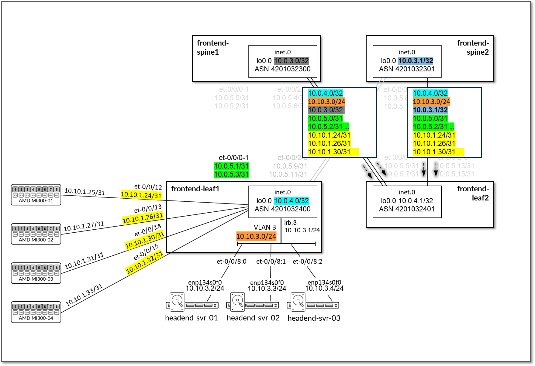
Table 31 Frontend Spine to Frontend Leaf Advertised Routes
| Leaf Node | Peer(s) | Advertised Routes | BGP Communities | |
|---|---|---|---|---|
| frontend-spine1 | frontend-leaf1 |
Loopbacks:10.0.3.0/32 10.0.4.0/32 Leaf1-spines links:10.0.5.0/31 10.0.5.2/31 10.0.5.8/31 10.0.5.10/31 . . . |
GPU servers <=> frontend spine links:10.10.1.24/31 10.10.1.26/31 10.10.1.30/31 10.10.1.32/31 Headend servers’ subnet: 10.10.3.0/24 |
0:15 1:20007 21001:26000 Except for 10.0.4.1/32 (0:15 4:20007 21001:26000) |
| frontend-spine2 | frontend-leaf1 |
Loopbacks:10.0.3.1/32 10.0.4.0/32 Leaf1-spines links:10.0.5.0/31 10.0.5.2/31 10.0.5.8/31 10.0.5.10/31 . . . |
GPU servers <=> frontend spine links:10.10.1.24/31 10.10.1.26/31 10.10.1.30/31 10.10.1.32/31 Headend servers’ subnet: 10.10.3.0/24 |
0:15 2:20007 21001:26000 Except for 10.0.4.1/32 (0:15 4:20007 21001:26000) |
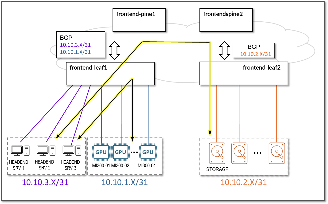
Advertising these subnets has the goal of allowing communication between the headend servers and the MI300X GPU server for AI job orchestration and monitoring, and between the headend servers and the storage devices connected to frontend-leaf2. Communication between the headend servers and storage devices is not discussed further in this document. Remember that the Vast storage devices are not connected to the frontend fabric.
Figure 103: Headend servers to GPU servers and storage devices across the frontend fabric.
GPU Backend Network Connectivity
The GPU backend fabric consists of four spine nodes (QFX5230-64CD) and eight leaf nodes (QFX5230-64CD) per stripe. Two AMD MI300X GPU servers are connected to each stripe, following the rail-optimized architecture described earlier in this document.
IP addressing
The GPU backend fabric is designed as a Layer 3 IP Fabric, with two 400GE links between each gpu-backend-leaf# node and each gpu-backend-spine# node. These links are configured with /31 IP addresses, as shown in Table 32 and Figure 104.
Figure 104: GPU Backend Spine to GPU Backend Leaf Nodes Connectivity
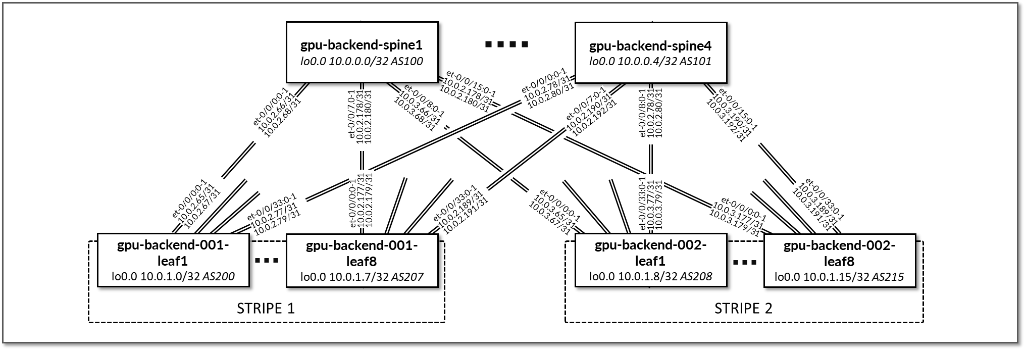
Table 32: GPU Backend Interface Addresses (sample)
| Stripe # | Leaf node | Leaf node | Spine IP address | Leaf IP address |
|---|---|---|---|---|
| 1 | gpu-backend-001-leaf1 | gpu-backend-spine1 |
10.0.2.65/31 10.0.2.67/31 |
10.0.2.1/31 10.0.2.3/31 |
| 1 | gpu-backend-001-leaf1 | gpu-backend-spine2 |
10.0.2.69/31 10.0.2.71/31 |
10.0.2.5/31 10.0.2.7/31 |
| 1 | gpu-backend-001-leaf1 | gpu-backend-spine3 |
10.0.2.73/31 10.0.2.75/31 |
10.0.2.9/31 10.0.2.11/31 |
| 1 | gpu-backend-001-leaf1 | gpu-backend-spine4 |
10.0.2.77/31 10.0.2.79/31 |
10.0.2.65/31 10.0.2.67/31 |
| 1 | gpu-backend-001-leaf2 | gpu-backend-spine1 |
10.0.2.81/31 10.0.2.83/31 |
10.0.2.69/31 10.0.2.71/31 |
| 1 | gpu-backend-001-leaf2 | gpu-backend-spine2 |
10.0.2.85/31 10.0.2.87/31 |
10.0.2.73/31 10.0.2.75/31 |
| . . . |
Table 33: GPU Backend Loopback Addresses (sample)
| Stripe # | Device | Loopback Interface Address |
|---|---|---|
| - | gpu-backend-spine1 | 10.0.0.0/32 |
| - | gpu-backend-spine2 | 10.0.0.1/32 |
| - | gpu-backend-spine3 | 10.0.0.2/32 |
| - | gpu-backend-spine4 | 10.0.0.3/32 |
| 1 | gpu-backend-001-leaf1 | 10.0.1.0/32 |
| 1 | gpu-backend-001-leaf2 | 10.0.1.1/32 |
| 1 | gpu-backend-001-leaf3 | 10.0.1.2/32 |
| . . . |
The AMD MI300X GPU Servers and Headend servers are all connected to gpu-backend-00#-leaf# nodes following the rail optimized architecture, as shown in Figure 105.
Figure 105: AMD MI300X GPU Servers connections to Storage Backend fabric
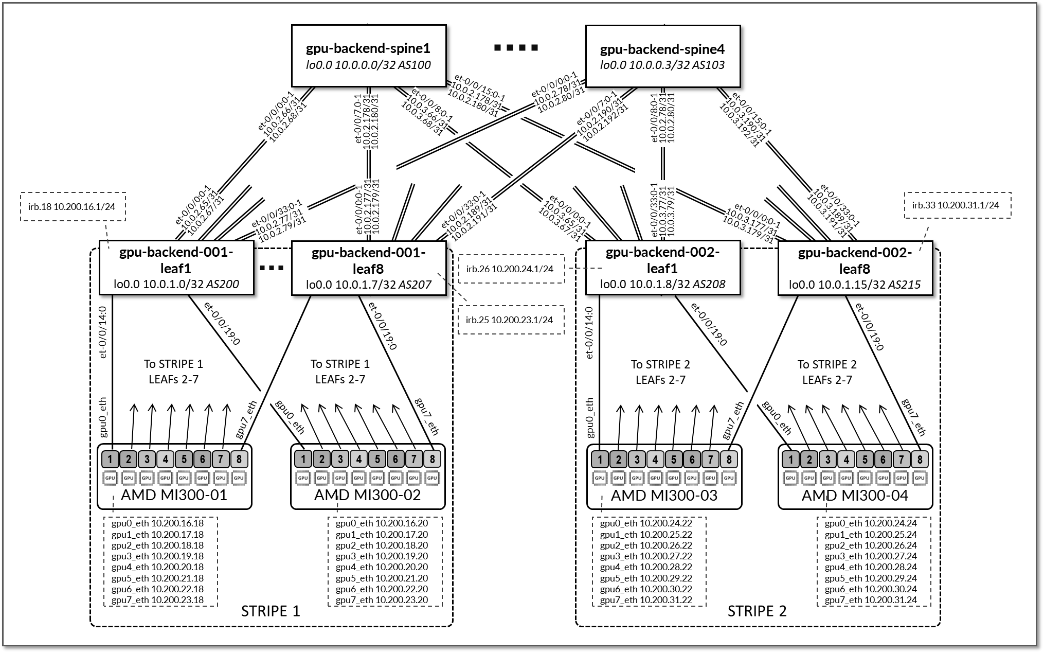
The links between the AMD MI300X GPU servers and the gpu-backend-00#-leaf# nodes do not have IP addresses assigned on the leaf node side. Layer 3 connectivity to the fabric is provided via irb interfaces with addresses 10.200.N.254/16, where N = 16, 17… (stripe/rail specific subnet), and the interfaces connected to the GPU servers are configured as L2 interfaces and are part of a unique vlan, as shown in Figure 106.
Figure 106: AMD MI300X GPU Servers rail optimized connections to Leaf nodes
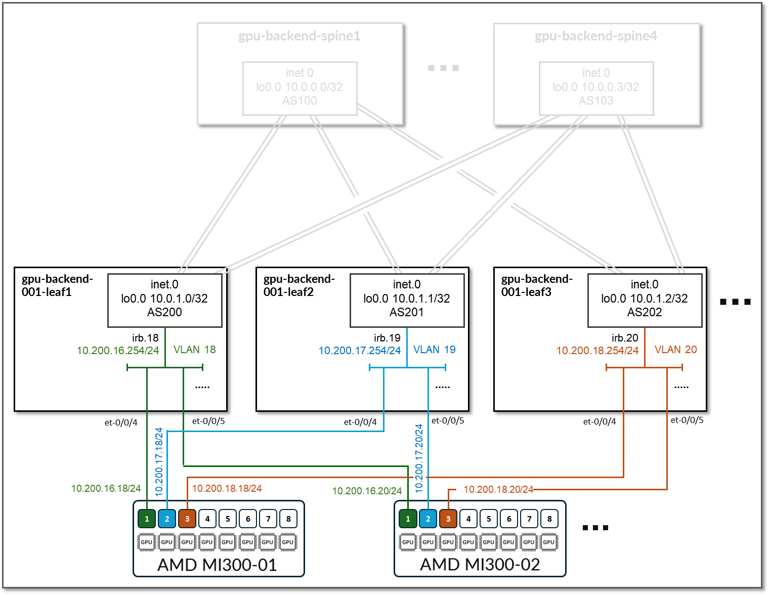
Each rail in the cluster is mapped to a different /24 IP subnet. The GPU servers are configured with addresses out of 10.200.N.<server>/24 and use 10.200.N.254/14 as their default gateway. Where:
| Server name | <server> | IP addresses |
|---|---|---|
| MI300X-01 | 18 | 10.200.N.18 24 |
| MI300X-02 | 20 | 10.200.N.20 24 |
| MI300X-03 | 22 | 10.200.N.22 24 |
| MI300X-04 | 24 | 10.200.N.24 24 |
Table 34: GPU Backend Servers to Leaf Nodes Connectivity
| Stripe # | Device | Rail # |
VLAN #/ IRB # |
Subnet | IRB on leaf | Connected device(s) |
|---|---|---|---|---|---|---|
| 1 | gpu-backend-leaf 1 | 1 | 18 | 10.200.16.0/24 | 10.200.16.254 | GPU 1 from the 2 GPU servers in the stripe |
| 1 | gpu-backend-leaf 2 | 2 | 19 | 10.200.17.0/24 | 10.200.17.254 | GPU 2 from the 2 GPU servers in the stripe |
| 1 | gpu-backend-leaf 3 | 3 | 20 | 10.200.18.0/24 | 10.200.18.254 | GPU 3 from the 2 GPU servers in the stripe |
| . . . | ||||||
Routing information
EBGP is configured between the IP addresses assigned to the spine-leaf links. There are two EBGP sessions between each gpu-backend-leaf# node and each gpu-backend-spine#.
Table 35: GPU Backend Sessions
| Stripe # | Spine Node | Leaf Node | Spine ASN | Leaf ASN | Spine IP Address | Leaf IP Address |
|---|---|---|---|---|---|---|
| 1 | gpu-backend-spine1 | gpu-backend-001-leaf1 | 4201032100 | 4201032200 |
10.0.2.0/31 10.0.2.2/31 |
10.0.2.1/31 10.0.2.3/31 |
| 1 | gpu-backend-spine1 | gpu-backend-001-leaf2 | 4201032201 |
10.0.2.4/31 10.0.2.6/31 |
10.0.2.5/31 10.0.2.7/31 |
|
| 1 | gpu-backend-spine1 | gpu-backend-001-leaf3 | 4201032202 |
10.0.2.8/31 10.0.2.10/31 |
10.0.2.9/31 10.0.2.11/31 |
|
|
. . . |
||||||
| 1 | gpu-backend-spine2 | gpu-backend-001-leaf1 | 4201032101 | 4201032208 |
10.0.2.64/31 10.0.2.66/31 |
10.0.2.65/31 10.0.2.67/31 |
| 1 | gpu-backend-spine2 | gpu-backend-001-leaf2 | 4201032209 |
10.0.2.68/31 10.0.2.70/31 |
10.0.2.69/31 10.0.2.71/31 |
|
| 1 | gpu-backend-spine2 | gpu-backend-001-leaf3 | 4201032210 |
10.0.2.72/31 10.0.2.74/31 |
10.0.2.73/31 10.0.2.75/31 |
|
| . . . |
On the Leaf nodes, BGP policies are configured by Apstra to advertise the following routes to the spine nodes:
- gpu-backend-000#leaf# nodes loopback interface addresses
- gpu-backend-000#leaf# nodes to gpu-backend-spine# nodes links /31 subnet address
- gpu-backend-00#-leaf# irb interface subnets (connecting the GPU servers)
Figure 107: GPU Backend Leaf to GPU Backend Spine advertised routers – routes to Vast AMD devices
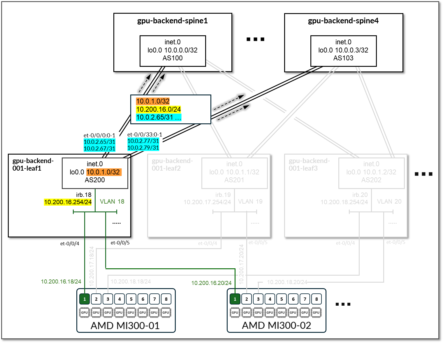
Table 36: GPU Backend Leaf Node Advertised Routes
| Stripe # | Device | Advertised routes | BGP community |
|---|---|---|---|
| 1 | gpu-backend-001-leaf 1 |
10.0.1.0/32 10.200.16.0/24 10.0.2.64/31 10.0.2.65/31 10.0.2.68/31 10.0.2.70/31 10.0.2.72/31 10.0.2.74/31 10.0.2.76/31 10.0.2.78/31 |
3:20007 21001:26000 |
| 1 | gpu-backend-001-leaf2 |
10.0.1.1/32 10.200.17.0/24 10.0.2.82/31 10.0.2.84/31 10.0.2.86/31 10.0.2.88/31 10.0.2.90/31 10.0.2.92/31 10.0.2.94/31 10.0.2.96/31 |
4:20007 21001:26000 |
| 1 | gpu-backend-001-leaf3 |
10.0.1.2/32 10.200.18.0/24 10.0.2.98/31 10.0.2.100/31 10.0.2.102/31 10.0.2.104/31 10.0.2.106/31 10.0.2.108/31 10.0.2.110/31 10.0.2.112/31 |
5:20007 21001:26000 |
| . . . |
On the Spine nodes, BGP policies are configured by Apstra to advertise the following routes to the gpu-backend-00#-leaf# nodes:
- gpu-backend-spine# node loopback interface address
- gpu-backend-00#-leaf# nodes loopback interface address
- gpu-backend-spine# nodes gpu-backend-00#-leaf# nodes links /31 subnet address
- gpu-backend-00#-leaf# irb interface subnets (connecting the GPU servers)
Figure 108: GPU Backend Spine to GPU Backend Leaf advertised routers – routes to Vast AMD devices
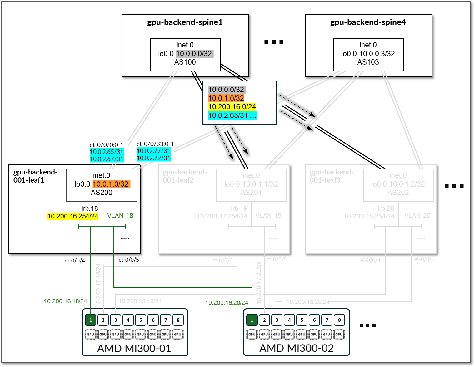
Table 37: GPU Backend Spine Node Advertised Routes
| Stripe # | Spine Node | Advertised Routes | BGP Community |
|---|---|---|---|
| 1 | gpu-backend-spine 1 |
10.0.0.0/32 10.0.0.1/32 10.0.0.2/32 10.0.0.3/32 10.0.1.0/31 10.0.1.2/31 10.0.1.3/31 … 10.200.16.0/24 10.200.17.0/24 … |
0:15 1:20007 21001:26000 |
| 1 | gpu-backend-spine 2 |
10.0.0.0/32 10.0.0.1/32 10.0.0.2/32 10.0.0.3/32 10.0.1.0/31 10.0.1.2/31 10.0.1.3/31 … 10.200.16.0/24 10.200.17.0/24 … |
0:15 2:20007 21001:26000 |
| . . . |
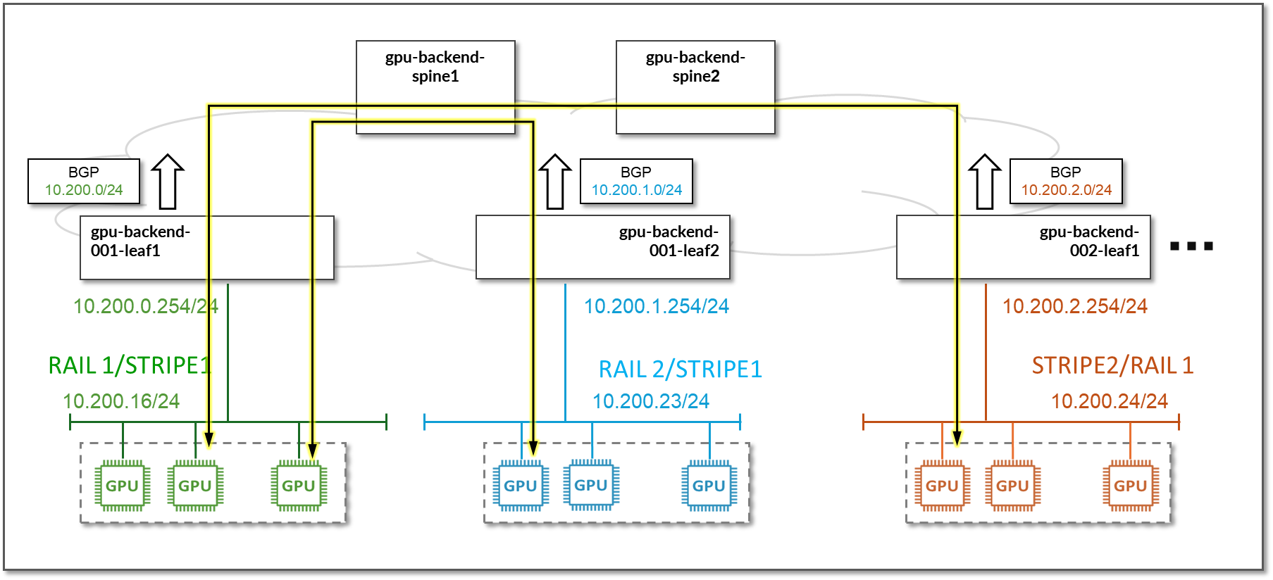
Advertising these subnets has the goal of allowing communication between the GPUs across all rails in stripes 1 and 2.
Figure 109: Communication Across Rails
Storage Backend Network Connectivity
The Storage Backend fabric consists of two spine nodes (QFX5220-32CD) and six leaf nodes (QFX5220-32CD), where two leaf nodes (storage-backend-gpu-leaf3 and storage-backend-gpu-leaf4) provide connectivity to the Vast storage devices, and the other four provide connectivity to the GPU servers including the AMD MI300X servers (storage-backend-gpu-leaf5 and storage-backend-gpu-leaf6) and other GPU servers in the lab.
IP addressing
The GPU Backend fabric is designed as a Layer 3 IP Fabric, with either two 400GE links between each storage-backend-gpu-leaf# node and each storage-backend-spine# node as shown in Figure 110. These links are configured with /31 IP addresses, as shown in Table 38.
Figure 110: Storage Backend Spine to Storage Backend GPU Leaf Nodes Connectivity
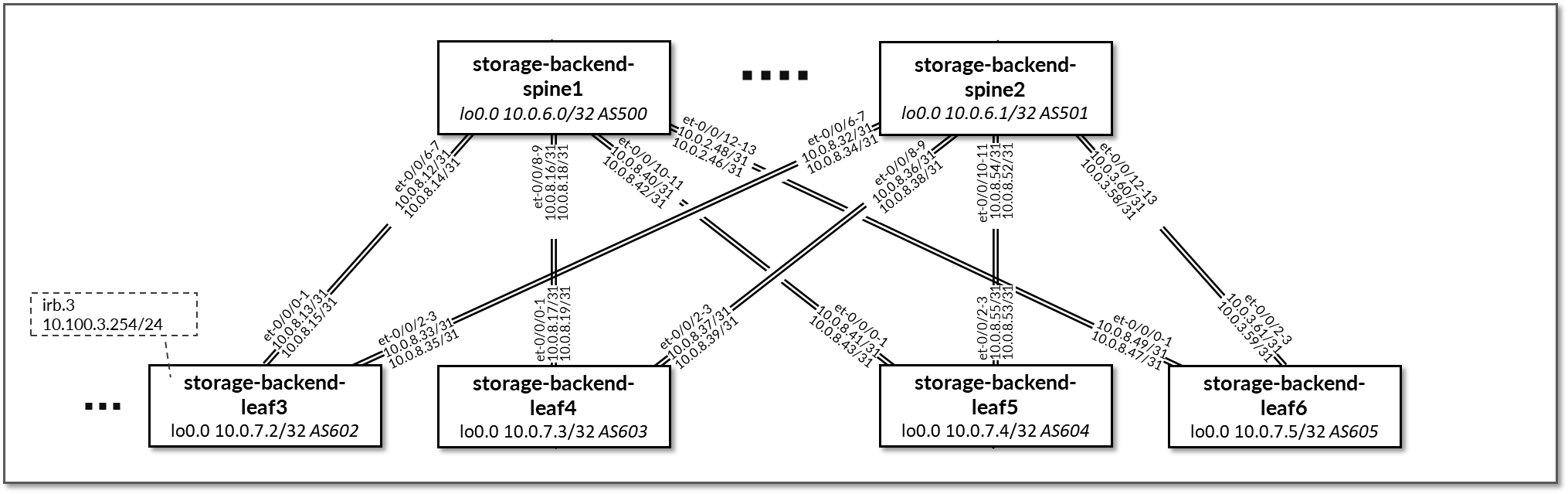
Table 38: Storage Backend Interface Addresses
| Spine node | Leaf node | Spine IP Address | Leaf IP Address |
|---|---|---|---|
| storage-backend-spine 1 | storage-backend-gpu-leaf 1 |
10.0.8.0/31 10.0.8.2/31 10.0.8.4/31 |
10.0.8.1/31 10.0.8.3/31 10.0.8.5/31 |
| storage-backend-spine1 | storage-backend-gpu-leaf2 |
10.0.8.6/31 10.0.8.8/31 10.0.8.10/31 |
10.0.8.7/31 10.0.8.9/31 10.0.8.11/31 |
| storage-backend-spine1 | storage-leaf 1 |
10.0.8.12/31 10.0.8.14/31 |
10.0.8.13/31 10.0.8.15/31 |
| storage-backend-spine1 | storage-leaf 2 |
10.0.8.16/31 10.0.8.18/31 |
10.0.8.17/31 10.0.8.19/31 |
| storage-backend-spine2 | storage-backend-gpu-leaf1 |
10.0.8.20/31 10.0.8.22/31 10.0.8.24/31 |
10.0.8.21/31 10.0.8.23/31 10.0.8.25/31 |
| storage-backend-spine2 | storage-backend-gpu-leaf2 |
10.0.8.26/31 10.0.8.28/31 10.0.8.30/31 |
10.0.8.27/31 10.0.8.29/31 10.0.8.31/31 |
| storage-backend-spine2 | storage-leaf 1 |
10.0.8.32/31 10.0.8.34/31 |
10.0.8.33/31 10.0.8.35/31 |
| storage-backend-spine2 | storage-leaf 2 |
10.0.8.36/31 10.0.8.38/31 |
10.0.8.37/31 10.0.8.39/31 |
Table 39: Storage Backend Loopback Interfaces
| Device | Loopback Interface Address |
|---|---|
| storage-backend-spine1 | 10.0.6.0/32 |
| storage-backend-spine2 | 10.0.6.1/32 |
| storage-backend-gpu-leaf3 | 10.0.7.2/32 |
| storage-backend-gpu-leaf4 | 10.0.7.3/32 |
| storage-backend-gpu-leaf5 | 10.0.7.4/32 |
| storage-backend-gpu-leaf6 | 10.0.7.5/32 |
The Vast C-nodes and AMD MI300Xs are dual homed and connected to storage leaf nodes 3-4, and 5-6, respectively.
Table 40. Vast storage and GPU servers to Backend fabric connections
| Device | Loopback Interface Address |
|---|---|
| Vast01--Vast08 |
storage-backend-gpu-leaf3 storage-backend-gpu-leaf4 |
| MI300X-01-- MI300X-04 |
storage-backend-gpu-leaf5 storage-backend-gpu-leaf6 |
The links between the VAST C-nodes and the storage-backend-leaf# nodes do not have IP addresses assigned on the leaf node side. Layer 3 connectivity to the fabric is provided via the irb.3 and irb.4 interfaces with addresses 10.200.3.254/24 (storage-backend-leaf3) 10.200.4.254/24 (storage-backend-leaf4) respectively. The interfaces connected to the GPU servers are configured as L2 interfaces and are part of a unique vlan which the irb interfaces are part of. This is similar to the GPU Backend Servers to Leaf Nodes Connectivity described in the previous section.
On the Vast side of these links, the C-nodes are dynamically assigned responsibility for traffic destined to the addresses that are part of the Virtual IP address pools 10.100.3.0/24 and 10.100.4.0/24, (under Network Access in the WebUI), as shown in the following table.
Figure 111: AMD M300I servers and Vast Storage connectivity to the Storage Backend
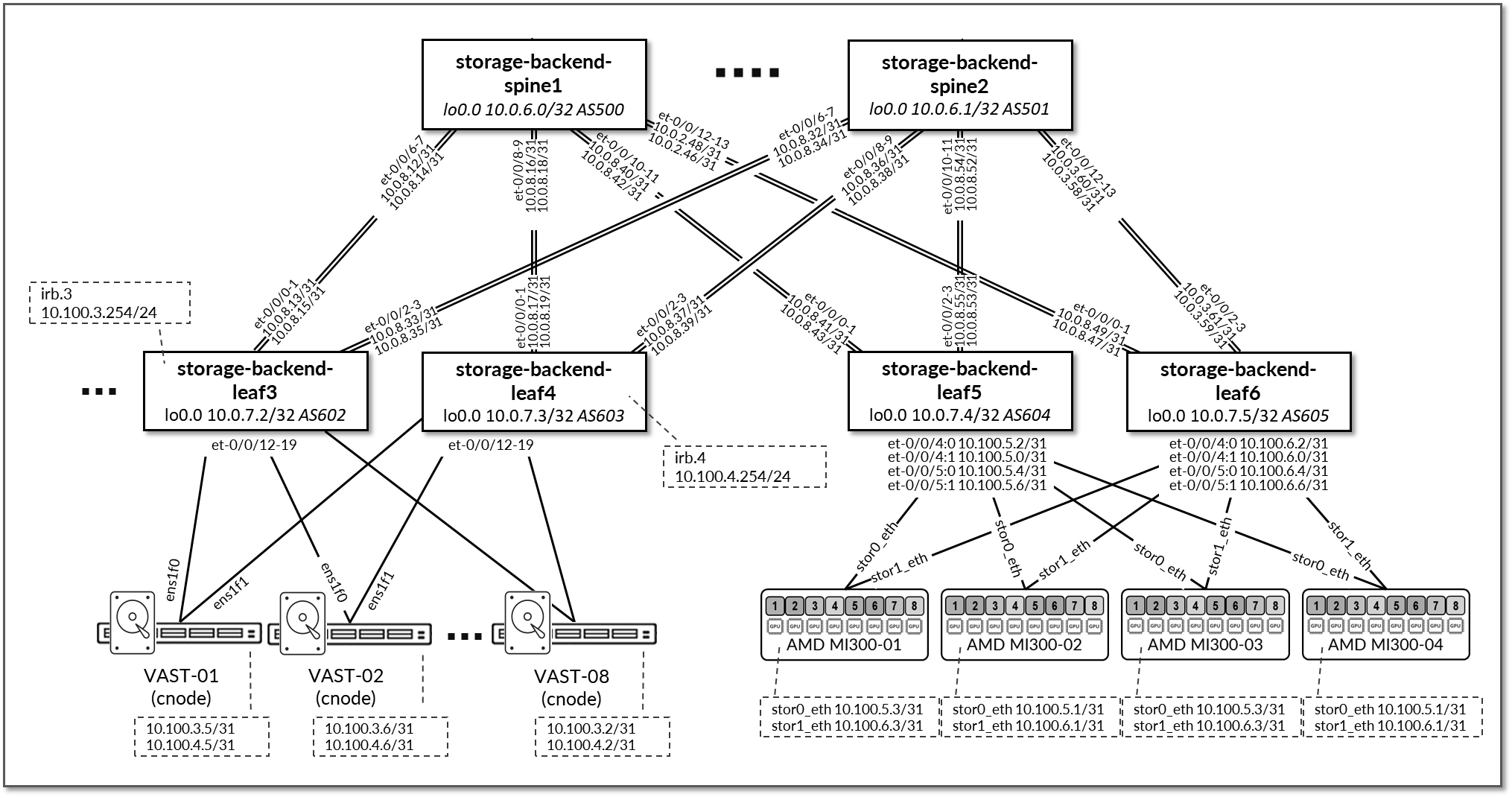
Table 41: Vast Storage to Leaf Nodes Interface Addresses
| Vast node | Leaf Node | VAST C-node IP Address | Leaf IP Address |
|---|---|---|---|
| Vast C-node 1 | storage-backend-leaf 3 | 10.100.3.5/24 | 10.100.3.254/24 (irb.3) |
| Vast C-node 1 | storage-backend-leaf 4 | 10.100.4.4/24 | 10.100.4.254/24 (irb.4) |
| Vast C-node 2 | storage-backend-leaf 3 | 10.100.3.6/24 | 10.100.3.254/24 (irb.3) |
| Vast C-node 2 | storage-backend-leaf 4 | 10.100.4.2/24 | 10.100.4.254/24 (irb.4) |
| Vast C-node 3 | storage-backend-leaf 3 | 10.100.3.4/24 | 10.100.3.254/24 (irb.3) |
| Vast C-node 3 | storage-backend-leaf 4 | 10.100.4.5/24 | 10.100.4.254/24 (irb.4) |
| Vast C-node 4 | storage-backend-leaf 3 | 10.100.3.1/24 | 10.100.3.254/24 (irb.3) |
| Vast C-node 4 | storage-backend-leaf 4 | 10.100.4.8/24 | 10.100.4.254/24 (irb.4) |
| Vast C-node 5 | storage-backend-leaf 3 | 10.100.3.3/24 | 10.100.3.254/24 (irb.3) |
| Vast C-node 5 | storage-backend-leaf 4 | 10.100.4.3/24 | 10.100.4.254/24 (irb.4) |
| Vast C-node 6 | storage-backend-leaf 3 | 10.100.3.8/24 | 10.100.3.254/24 (irb.3) |
| Vast C-node 6 | storage-backend-leaf 4 | 10.100.4.1/24 | 10.100.4.254/24 (irb.4) |
| Vast C-node 7 | storage-backend-leaf 3 | 10.100.3.7/24 | 10.100.3.254/24 (irb.3) |
| Vast C-node 7 | storage-backend-leaf 4 | 10.100.4.6/24 | 10.100.4.254/24 (irb.4) |
| Vast C-node 8 | storage-backend-leaf 3 | 10.100.3.2/24 | 10.100.3.254/24 (irb.3) |
| Vast C-node 8 | storage-backend-leaf 4 | 10.100.4.7/24 | 10.100.4.254/24 (irb.4) |
The links between the GPU servers and storage-backend-gpu-leaf# are configured with /31 subnets out of 10.100.1/24 by Apstra.
Table 42: GPU Servers to Storage GPU Backend Interface Addresses
| GPU Server | Leaf Node | GPU Server IP Address | Leaf IP Address |
|---|---|---|---|
| MI300X-01 | storage-backend-gpu-leaf5 | 10.100.5.1/31 | 10.100.5.0/31 |
| MI300X-01 | storage-backend-gpu-leaf6 | 10.100.6.1/31 | 10.100.6.0/31 |
| MI300X-02 | storage-backend-gpu-leaf5 | 10.100.5.3/31 | 10.100.5.2/31 |
| MI300X-02 | storage-backend-gpu-leaf6 | 10.100.6.3/31 | 10.100.6.2/31 |
| MI300X-03 | storage-backend-gpu-leaf5 | 10.100.5.5/31 | 10.100.5.4/31 |
| MI300X-03 | storage-backend-gpu-leaf6 | 10.100.6.5/31 | 10.100.6.4/31 |
| MI300X-04 | storage-backend-gpu-leaf5 | 10.100.5.7/31 | 10.100.5.6/31 |
| MI300X-04 | storage-backend-gpu-leaf6 | 10.100.6.7/31 | 10.100.6.6/31 |
Routing information
EBGP is configured between the IP addresses assigned to the spine-leaf links. There are two EBGP sessions between each storage-backend-leaf# node and each storage-backend-spine#, as shown in Figure 112
Table 43: Storage Backend Sessions
| Spine Node | Leaf Node | Spine ASN | Leaf ASN | Spine IP Address | Leaf IP Address |
|---|---|---|---|---|---|
| storage-backend-spine1 | storage-backend-gpu-leaf3 | 4201032500 | 4201032602 |
10.0.8.12/31 10.0.8.14/31 |
10.0.8.13/31 10.0.8.15/31 |
| storage-backend-spine1 | storage-backend-gpu-leaf4 | 4201032603 |
10.0.8.16/31 10.0.8.18/31 |
10.0.8.17/31 10.0.8.19/31 |
|
| storage-backend-spine1 | storage-backend-gpu-leaf5 | 4201032604 |
10.0.8.40/31 10.0.8.42/31 |
10.0.8.41/31 10.0.8.43/31 |
|
| storage-backend-spine1 | storage-backend-gpu-leaf6 | 4201032605 |
10.0.8.46/31 10.0.8.48/31 |
10.0.8.47/31 10.0.8.49/31 |
|
| storage-backend-spine2 | storage-backend-gpu-leaf3 | 4201032501 | 4201032602 |
10.0.8.32/31 10.0.8.34/31 |
10.0.8.33/31 10.0.8.35/31 |
| storage-backend-spine2 | storage-backend-gpu-leaf4 | 4201032603 |
10.0.8.36/31 10.0.8.38/31 |
10.0.8.37/31 10.0.8.39/31 |
|
| storage-backend-spine2 | storage-backend-gpu-leaf5 | 4201032604 |
10.0.8.52/31 10.0.8.54/31 |
10.0.8.53/31 10.0.8.55/31 |
|
| storage-backend-spine2 | storage-backend-gpu-leaf6 | 4201032605 |
10.0.8.56/31 10.0.8.58/31 |
10.0.8.57/31 10.0.8.59/31 |
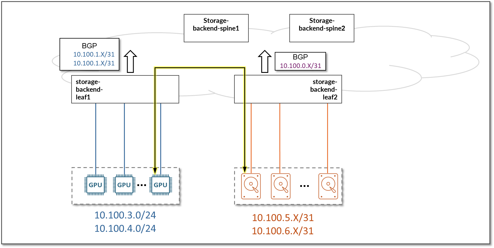
On the Leaf nodes, BGP policies are configured by Apstra to advertise the following routes to the spine nodes:
- storage-backend-leaf# nodes loopback interface addresses
- storage-backend-leaf# nodes to storage-backend-spine# interfaces subnets
- storage-backend-leaf3, storage-backend-leaf4 nodes irb interface (connection to Vast C-nodes)
- storage-backend-leaf5, storage-backend-leaf6 nodes to storage-backend-spine# interfaces subnets (connection to MI300X servers)
Figure 112: Storage Backend Leaf to Storage Backend Spines advertised routers – routes to Vast Storage devices and MI300X servers
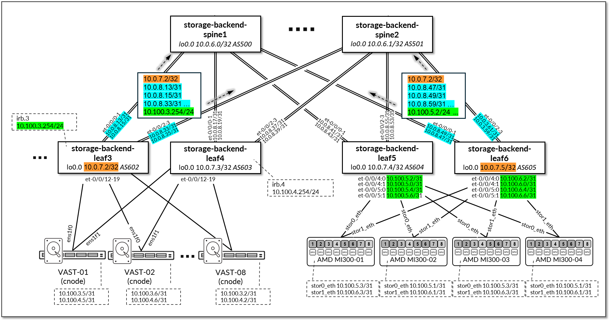
Table 44: Storage Backend Leaf Node Advertised Routes
| Leaf Node | Peer | Advertised Routes | BGP Communities | |
|---|---|---|---|---|
| storage-backend-leaf3 |
storage-backend-spine1 & storage-backend-spine2 |
10.0.7.2/32 10.0.8.12/31 10.0.8.14/31 10.0.8.32/31 10.0.8.34/31 10.100.3.0/24 |
5:20007 21001:26000 |
|
| storage-backend-leaf4 |
storage-backend-spine1 & storage-backend-spine2 |
10.0.7.3/32 10.0.8.16/31 10.0.8.18/31 10.0.8.36/31 10.0.8.38/31 10.100.4.0/24 |
6:20007 21001:26000 |
|
| storage-backend-leaf5 |
storage-backend-spine1 & storage-backend-spine2 |
10.0.7.4/32 10.0.8.40/31 10.0.8.42/31 10.0.8.52/31 10.0.8.54/31 |
10.100.5.0/31 10.100.5.2/31 10.100.5.4/31 10.100.5.6/31 |
7:20007 21001:26000 |
| storage-backend-leaf6 |
storage-backend-spine1 & storage-backend-spine2 |
10.0.7.5/32 10.0.8.46/31 10.0.8.48/31 10.0.8.58/31 10.0.8.60/31 |
10.100.6.0/31 10.100.6.2/31 10.100.6.4/31 10.100.6.6/31 |
8:20007 21001:26000 |
On the Spine nodes, BGP policies are configured by Apstra to advertise the following routes to the leaf nodes:
- storage-backend-leaf# nodes loopback interface addresses
- storage-backend-spine# nodes loopback interface addresses
- storage-backend-leaf# nodes to storage-backend-spine# interfaces subnets
- storage-backend-leaf3, storage-backend-leaf4 nodes irb interface (connection to Vast C-nodes)
- storage-backend-leaf5, storage-backend-leaf6 nodes to storage-backend-spine# interfaces subnets (connection to MI300X servers)
Figure 113: Storage Backend Spine to Storage Backend Leafs advertised routers – routes to Vast Storage devices and MI300X servers
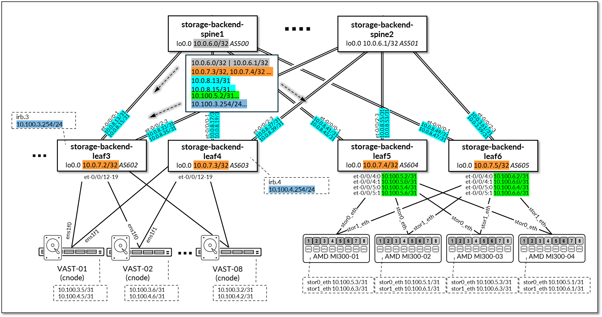
Table 45: Storage Backend Spine Node Advertised Routes
| Leaf Node | Peer | Advertised Routes | BGP Communities | ||
|---|---|---|---|---|---|
| storage-backend-spine1 | storage-backend-leaf3 |
10.0.6.0/32 10.0.7.0/32 10.0.7.1/32 10.0.7.3/32 10.0.7.4/32 10.0.7.5/32 |
10.100.4.0/24 10.100.5.0/31 10.100.5.2/31 10.100.5.4/31 10.100.5.6/31 |
10.100.6.0/31 10.100.6.2/31 10.100.6.4/31 10.100.6.6/31 10.0.8.33/31 … 10.0.8.41/31 … 10.0.8.49/31 … |
0:15 6:20007 21001:26000 |
| storage-backend-spine1 | storage-backend-leaf4 |
10.0.6.0/32 10.0.7.0/32 10.0.7.1/32 10.0.7.2/32 10.0.7.4/32 10.0.7.5/32 |
10.100.3.0/24 10.100.5.0/31 10.100.5.2/31 10.100.5.4/31 10.100.5.6/31 |
10.100.6.0/31 10.100.6.2/31 10.100.6.4/31 10.100.6.6/31 10.0.8.13/31 … 10.0.8.41/31 … 10.0.8.49/31 … |
0:15 6:20007 21001:26000 |
| storage-backend-spine1 | storage-backend-leaf5 |
10.0.6.0/32 10.0.7.0/32 10.0.7.1/32 10.0.7.2/32 10.0.7.3/32 10.0.7.5/32 |
10.100.3.0/24 10.100.4.0/24 |
10.0.8.13/31 … 10.0.8.33/31 … 10.0.8.41/31 … |
0:15 6:20007 21001:26000 |
| storage-backend-spine1 | storage-backend-leaf6 |
10.0.6.0/32 10.0.7.0/32 10.0.7.1/32 10.0.7.2/32 10.0.7.3/32 10.0.7.4/32 |
10.100.3.0/24 10.100.4.0/24 |
10.0.8.13/31 … 10.0.8.33/31 … 10.0.8.49/31 … |
0:15 6:20007 21001:26000 |
| storage-backend-spine2 | storage-backend-leaf5 |
10.0.6.1/32 10.0.7.0/32 10.0.7.1/32 10.0.7.3/32 10.0.7.4/32 10.0.7.5/32 |
10.100.4.0/24 |
10.100.6.0/31 10.100.6.2/31 10.100.6.4/31 10.100.6.6/31 10.0.8.33/31 … 10.0.8.41/31 … 10.0.8.49/31 … |
0:15 4:20007 21001:26000 |
| . . . | |||||
Advertising these subnets has the goal of allowing communication between the MI300X GPU servers and Vast Storage devices.
Figure 114: Communication between GPU servers and Storage devices