Use Case and Reference Architecture
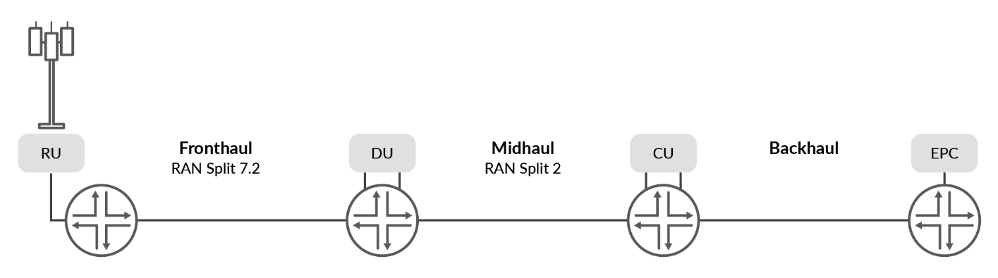
The 5G xHaul architecture encompasses three physical segments: Fronthaul, Midhaul, and Backhaul as shown in Figure 1.
The validated design addresses the convergence of 5G xHaul by leveraging seamless segment routing technologies.
Fronthaul segment enables Layer 2 connectivity between Open Radio Unit (O-RU) (cell site) and Open Distributed Unit (O-DU) (shown as RU and DU in Figure 1) in the radio access network (RAN), allowing them to communicate for control, data, and management traffic. It also ensures time and frequency synchronization between RAN elements. Because low latency is crucial (must be below 150µs from RU to DU), the Fronthaul segment has very few network elements, typically limited to one or two hops. The current solution for 5G Fronthaul transport is based on O-RAN Alliance architecture [ORAN-WG9.XPSAAS.0-v00.01].
Midhaul segment of the 5G network infrastructure defines the disaggregated RAN, responsible for supporting gNodeB-Centralized unit (gNB-CU) to gNB-DU communication. De-aggregated gNB consists of O-CU Control Plane (O-CU-CP) and CU User Plane (O-CU-UP), connected to the corresponding O-DU over F1-C (control) and F1-U (data) interfaces. Interconnecting CU-CP and CU-UP by E1 interface specified by 3rd Generation Partnership Project (3GPP) TS 38.401.
Backhaul network defines the infrastructure connecting the 5G mobile core to CU. Control and user planes are assigned into unique VPNs for separation between user data and 3GPP control plane.
Midhaul and Backhaul architectures do not require the same latency budgets as Fronthaul and are represented as ring, mesh, hub-and-spoke, or spine-and-leaf topologies.
The validated design establishes these domains and device roles by following recommendations of O-RAN Alliance [ORAN-WG9.XPSAAS.0-v00.01]. The key attributes of the transport network architectures are considered with establishment of strict latency budgets, traffic prioritization, packet loss tolerance, fault management, and bandwidth requirements for meeting the demands across Fronthaul, Midhaul, and Backhaul segments. For the 5G xHaul JVD, the primary focus is on the mobile backhaul (MBH) transport architecture and services at scale. The infrastructure is expected to support diverse residential, business, and wholesale services concurrently with end-to-end 4G/5G mobile operator applications. The JVD proposes color-aware service mapping that enables granular end-to-end traffic steering across disparate domains.
The evolution of the RAN encompasses distributed, centralized, and virtual 4G architectures that must coexist with the 5G disaggregated O-RAN. These diverse ecosystems allow flexible insertion points for O-DU/O-CU components. The dissection of RAN functional splits proposed by 3GPP and O-RAN for supporting disaggregated deployment models are outside the scope of this document but an important attribute in the proposed architecture.
Figure 2 as referenced by O-RAN Alliance [O-RAN.WG9.XPSAAS-v02.00], summarizes RAN deployment scenarios according to the ITU-T GSTP-TN5G for concurrent 4G and 5G support.
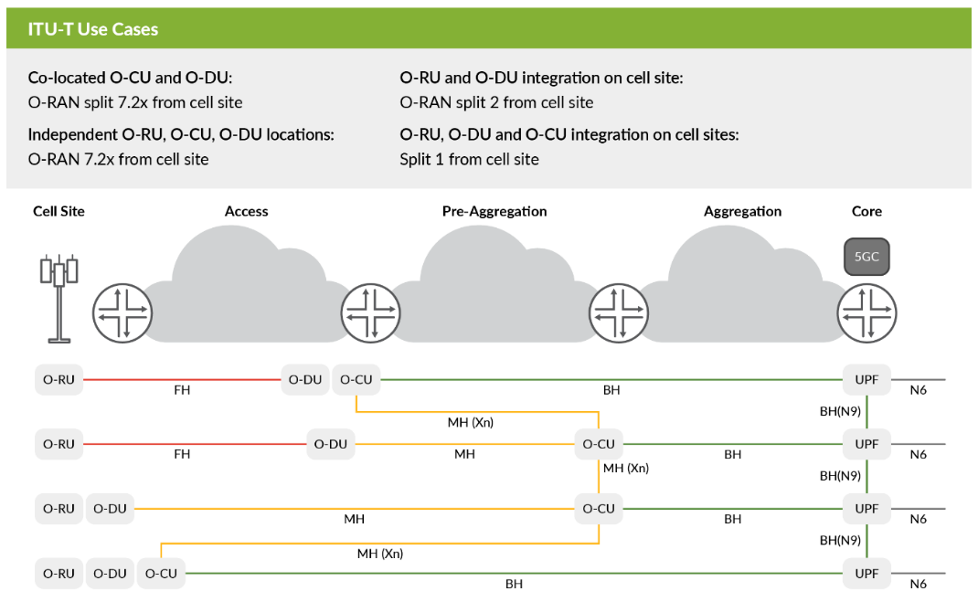
This JVD does not attempt to cover all possibilities and instead deploys an integrated Backhaul model. Additional insertion points for split architectures can be engineered to support disaggregation between Midhaul and Backhaul segments by extending appropriate services.
The ability to support complex concurrent network architectures further prioritizes delivery of seamless end-to-end solutions. A foundational emphasis of the 5G xHaul JVD is in demonstrating network pre-slicing solutions where overlay services might be mapped to underlay transport across a seamless converged mobile network.
Figure 3 shows a seamless end-to-end MBH network, modeled after common topology [O-RAN.WG9.XPSAAS-v02.00], which defines four segments of transport infrastructure: access, pre-aggregation, aggregation, and transport core.
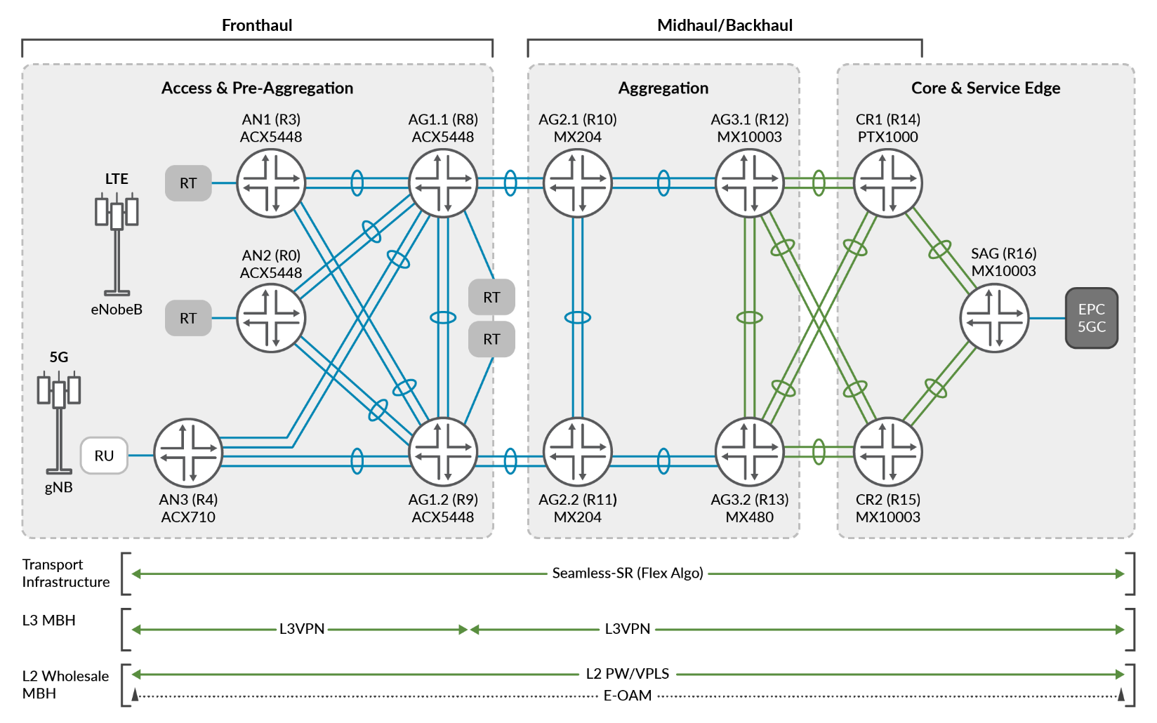
Topology Definitions:
- Access—Includes ACX710 & ACX5448 Access Nodes (AN1, AN2, AN3) cell site routers.
- Pre-Aggregation—Includes ACX5448 hub site routers AG1.1 and AG1.2.
- Aggregation—Includes aggregation routers AG2.1/AG2.2 (MX204) and AG3.1/AG3.2 (MX10003/MX480).
- Core Network—Includes core routers CR1/CR2 (PTX1000/MX10003) and service router SAG (MX10003).
Spine-leaf access topology establishes 5G Fronthaul segment with redundant hub site routers (HSR) – AG1.1 and AG1.2 in Figure 3 and collapses 4G Pre-Aggregation and 5G HSR roles. Pre-Aggregation AG1 nodes include additional access insertion points (RT) for scaling the environment. Midhaul and Backhaul segments, represented by ring topologies, are combined to include Aggregation and Core roles.
Underlay consists of seamless segment routing L-ISIS, Prefix-SID, and BGP-LU stitching at border nodes, as shown in Figure 4:
- Access nodes and Pre-Aggregation segments reside within Level 1 ISIS domain.
- Pre-Aggregation segment includes L1/L2 ISIS routers.
- Pre-Aggregation, Aggregation, and Core segments reside within a Level 2 ISIS domain.
- TI-LFA node redundancy is supported within each domain instantiation.
- Flex-Algo underlay slicing further partitions the SR-MPLS xHaul network into colored paths with two Flexible Algorithm Definitions (FAD), including red (128) and blue (129) using IGP and TE metrics.
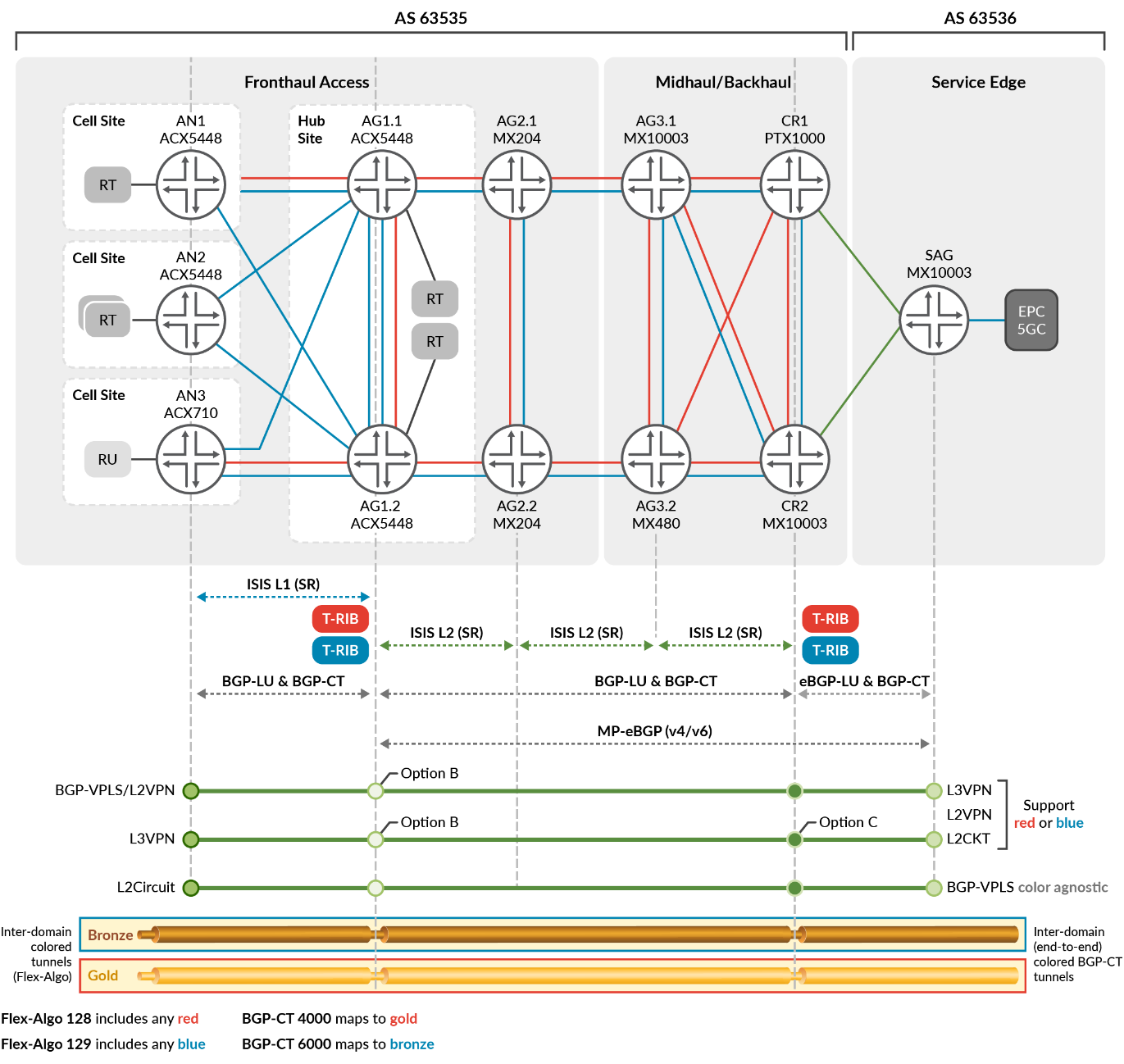
While BGP-LU and Inter-AS solutions can meet seamless E2E requirements, these do not satisfy service aware traffic engineering SLAs. BGP-CT provides network slicing and dynamic traffic steering based on transport classes, which are determined by route target attributes.
Color-aware overlay services are mapped end-to-end across domains with BGP-CT. Gold and bronze transport classes are defined so that gold is mapped to paths which include only red (128) algo and bronze is mapped to paths which include only blue (129) algo. In the event gold or bronze paths are unavailable, the network is designed to fallback to inet.3 (color agnostic) path selection.
The validated design includes the following overlay services:
- Layer 3 VPN includes termination points on all Access Nodes, AG1.1/AG1.2, and SAG. L3VPN supports BGP-CT per-prefix color-mapping. Routes received with protocol direct or OSPF are mapped to transport class gold and traverse the flex-algo slice denoted as red (128), while BGP-learned routes matching specific attributes are mapped to bronze transport class and blue algo (129).
- Layer 2 VPN includes termination points on all Access Nodes, AG1.1/AG1.2, and SAG. MP-BGP L2VPN supports BGP-CT color-mapping. All customer routes exported by the L2VPN instance are mapped to either gold or bronze transport classes and traverse only the corresponding flex-algo slice.
- Layer 2 Circuit includes termination points on AN3, AG1.1/AG1.2, and SAG. L2Circuit supports BGP-CT as a community mapping assignment. L2Circuits are assigned gold or bronze traffic class and traverse only corresponding algo.
- BGP-VPLS includes termination points on AN1, AN3, AG1.1/AG1.2, and SAG. VPLS is deployed to traverse the topology as color-agnostic services, demonstrating the coexistence with color-aware service mapping. BGP-VPLS supports BGP Classful Transport with service mapping from Junos OS Release 21.4R1 and later releases.