Solution Design and Architecture
Figure 1 shows an end-to-end 5G xHaul network, modeled after common topology [O-RAN.WG9.XPSAAS-v02.00], which defines four segments of transport infrastructure: access, pre-aggregation, aggregation, and transport core. Foundational technologies incorporate modern and legacy VPN services over segment routing.
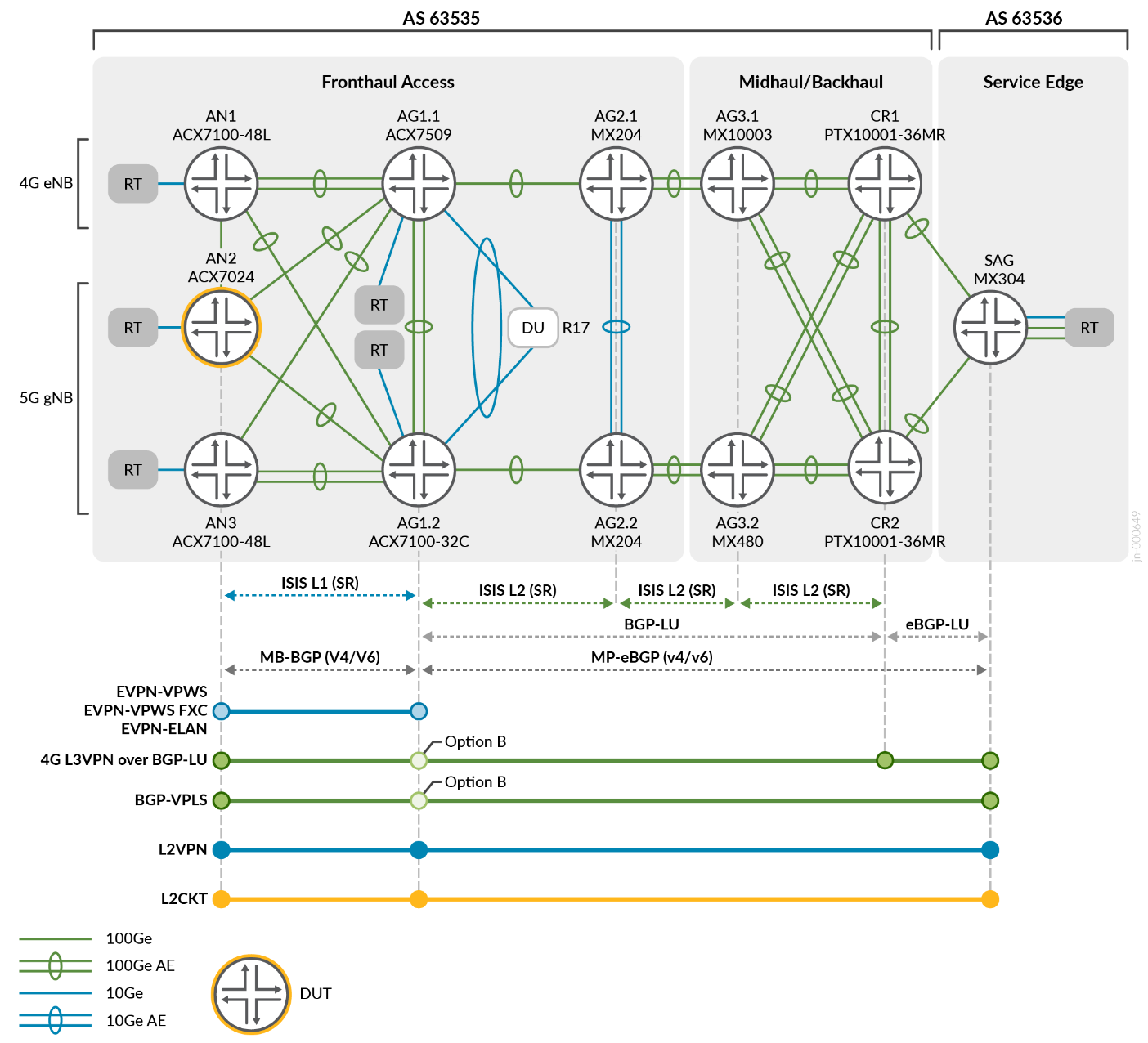
The Fronthaul network deployment scenarios were carefully designed to support both the traditional 4G MBH and the evolution into the 5G network infrastructure over the same physical network. This approach allows MSOs to make a smooth transition from 4G to 5G without disrupting their existing services. They can gradually introduce the necessary changes and upgrades to accommodate the new requirements of 5G networks.
The network underlay features SR-MPLS across multiple ISIS domains and inter-AS. Access nodes are placed into an ISIS L1 domain with adjacencies to L1/L2 HSR nodes where L2 domain extends from aggregation to core segments. Seamless MPLS is achieved by enabling BGP Labeled Unicast (BGP-LU) at border nodes.
Table 1 summarizes the choice of protocols.
| Fronthaul | Midhaul/Backhaul | SAG | |
|---|---|---|---|
| IGP | ISIS L1/L2 | ISIS L2 | - |
| Intra-Domain MPLS Tunnel | SR-ISIS | SR-ISIS | - |
| Protection | TI-LFA | TI-LFA | - |
| Inter-Domain Transport | - | BGP-LU (Option B) | BGP-LU (Option C) |
To handle the increased network scale, two sets of route reflectors are used at CR1 and CR2, primarily serving the westward HSR (AG1) clients. AG1.1/AG1.2 act as redundant route reflectors specifically for the access Fronthaul segment. Inter-AS Option-B solutions are supported through Multi-Protocol BGP peering between the Services Aggregation Gateway router (SAG) and the HSR (AG1).
Overlay Services
The overlay services in the network use different combinations of VLAN operations. These operations are applied to various Layer 2 service types such as EVPN-ELAN, EVPN-VPWS, EVPN-FXC, L2Circuit, VPLS, and L2VPN. Starting with Junos OS Evolved Release 22.3R1, Flow Aware Transport Pseudowire Label (FAT-PW) is supported for L2Circuit and L2VPN services and is included in this JVD. Ethernet OAM with performance monitoring is enabled for EVPN Fronthaul and VPLS MBH services, ensuring effective monitoring of the network performance. Additionally, L3VPN services incorporate IPv6 tunnelling to validate IPv6 PE functionality.
The following combination of VPNs is designed in a way to allow following traffic flows in the 5G xHaul network:
- Layer 2 eCPRI (emulated) between O-RU to O-DU traffic flows¾5G Fronthaul
- Layer 3 IP packet flows between 4G CSR and EPC (SAG)¾4G L3-MBH
- Layer 2 flows between CSR (AN) to EPC (SAG)¾4G L2-MBH
- Layer 3 IP packet flows between 5G O-DU and CU/EPC¾5G Midhaul and Backhaul
- Layer 2 Midhaul flows emulating additional attachment segments¾4G Midhaul and Backhaul
Connectivity Models
There are two connectivity models between O-RU and O-DU. These models leverage the following EVPN-VPWS, EVPN-FXC or EVPN-ELAN services:
- EVPN-VPWS single-homed supporting dedicated MAC for eCPRI without redundancy
- EVPN-FXC VLAN-AWARE single-homed supporting dedicated MAC for eCPRI without redundancy
- EVPN-VPWS with A/A ESI LAG DU attachment
- EVPN-FXC VLAN-AWARE with A/A LAG DU attachment
- EVPN-ELAN with A/A ESI LAG DU attachment
Figure 2 illustrates the first connectivity model. In this scenario, the network utilizes EVPN-VPWS single-homing connectivity. This setup supports dedicated MAC for eCPRI without redundancy. Additionally, it uses Ethernet OAM with performance monitoring. However, it is important to note that Ethernet OAM with performance monitoring is only supported for the single-homed configuration in this model.
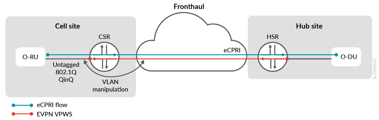
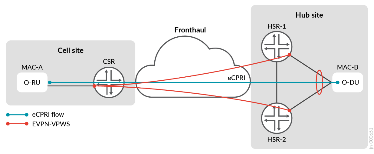
Figure 3 illustrates the second connectivity model. This model uses either EVPN-VPWS or EVPN-ELAN with active/active multihoming. Additionally, it uses EVPN-VPWS with FXC active/active multihoming from CSR (AN4) to HSR (AG1.1/AG1.2). The HSR devices are connected to the O-DU through an active/active Ethernet Segment Identifier (ESI) Link Aggregation Group (LAG), enabling the sharing of traffic load. The links are bundled into an active/active EVPN ESI 10Ge LAG between AG1.1 and AG1.2, as well as to the O-DU, which consists of a two-member Aggregate Ethernet (AE) with both links actively functioning. In this configuration, eCPRI packets might arrive on either O-DU link from the HSRs, while eCPRI packets are transmitted across either HSR uplink for active/active operations.
To enable traffic load sharing, an active/active ESI LAG is established between the HSRs and the O-DU. This allows for balanced distribution of traffic. The links are bundled into an active/active EVPN ESI 10G Ethernet LAG between HSR-1 and HSR-2, as well as to the O-DU. The O-DU includes a two-member AE with both links actively carrying traffic.
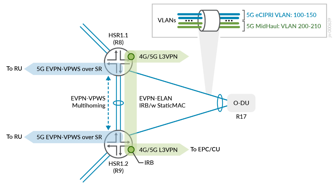
Layer 3 Connectivity Models
We chose L3VPN protocol to facilitate Layer 3 connectivity between O-DU and vCU/vEPC elements of the 5G xHaul. Two unique connectivity are proposed, with both supporting Layer 3 multihoming between O-DU and pair of HSRs:
- EVPN IRB anycast gateway with L3VPN
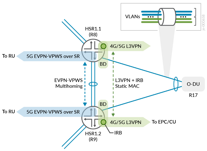
- BD with IRB and static MAC/ARP with L3VPN
The two corresponding models are referred to as EVPN IRB with L3VPN and BD IRB with L3VPN, respectively, see Figure 4 and Figure 5 . For more details about configurations for these connectivity models, contact your Juniper Networks representative.
5G QoS Identifier (5QI) Model
When transitioning from the 4G LTE Quality of Service Class Identifier (QCI) model to the flow-based 5G QoS Identifier (5QI) model, most traffic definitions overlap. However, 5G introduces new categories for delay-critical Guaranteed Bit Rate (GBR) flows. In the 5G Fronthaul segment, eCPRI-based flows handle user and control traffic between the O-RU and O-DU. These flows require high bandwidth and extremely low delay. Therefore, all devices in the access topology must prioritize this traffic type with the highest priority.
The O-RAN specification [O-RAN.WG9.XPSAAS-v02.00] proposes a model to group common QCI and 5QI flow characteristics into four exemplary groups based on their delay budget. This grouping aims to provide a framework for defining the QoS for different types of traffic in the 5G network. Refer to Figure 6 .
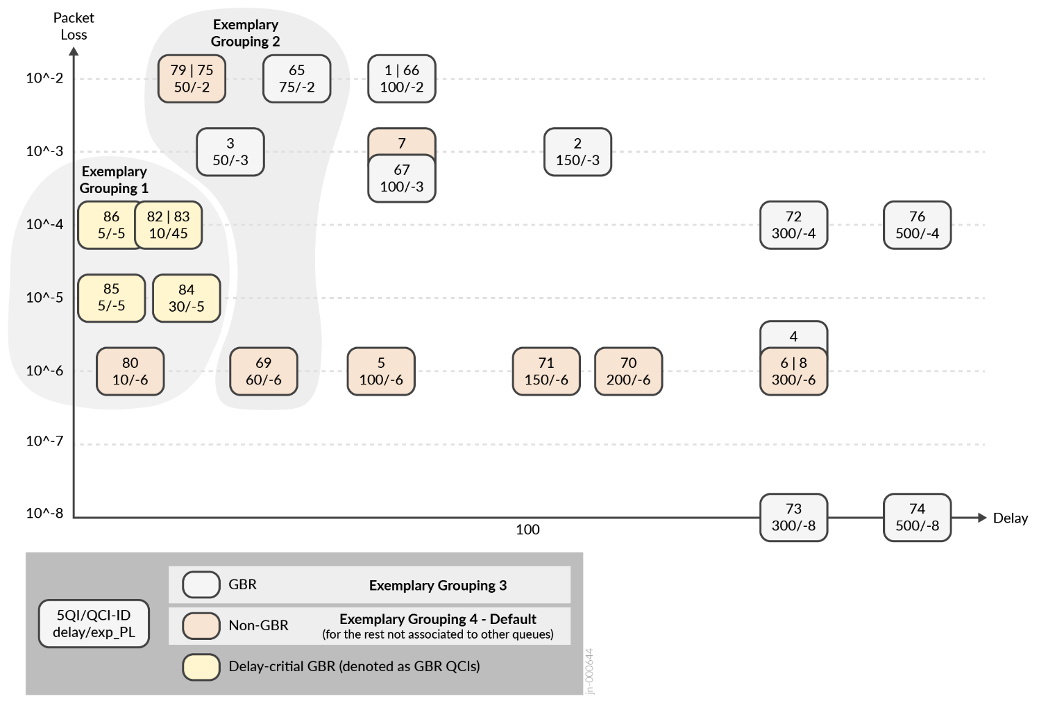
QoS schemas can differ among mobile operators, and this JVD does not endorse a specific design as the recommended one. The objective is to establish predictable behaviors for critical and non-critical traffic flows across various services delivered by the xHaul network. The transport architecture needs to demonstrate its capability to accommodate existing and emerging mobile applications while maintaining the integrity of the delay budget and ensuring traffic priorities.
For more details on the specific latency and delay budgets considered for this JVD, contact your Juniper Networks representative.
QoS Profiles
O-RAN/3GPP proposes two common QoS profiles to meet the requirements of the transport network. In Profile A, illustrated in Figure 7 , a single priority queue is defined to handle ultra-low latency flows such as Precision Time Protocol (PTP) and eCPRI. This queue is given priority over all other queues. Lower priority queues are then serviced using weighted fair queuing (WFQ) round-robin scheduling. The ACX7000 series are best suited for Profile A.
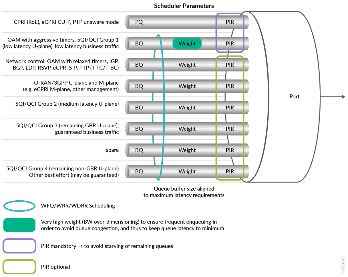
The Profile B model uses a hierarchy of queue priorities: high, medium, and low. These priority queues support preemption to minimize packet delay variations (PDV) and prioritize critical flows that require low latency. Specifically, the queue assigned for eCPRI traffic needs to have the ability to interrupt or take priority over other queues.
As of Junos OS Evolved Release 22.3R2, ACX Metro Routers support multiple strict-high (SH) or low priority queues. Strict-high queues are serviced as round-robin without the ability to preempt another priority queue. Profile A is selected for this JVD, reserving a strict-high queue for ultra-low latency between RU and DU.
Class of Service Building Blocks
Class of Service (CoS) governs how traffic is forwarded, stored, or dropped in conjunction with mechanisms to manage and avoid congestion. CoS is comprised with the following basic building blocks:
- Classification
- Scheduling and Queuing
- Rewriting
- Shaping and Rate Limiting
CoS models differ between operators based on unique traffic profiles and characteristics. Table 2 defines a pseudo-customer model that we used for this JVD. For more details on this CoS model, contact your Juniper Networks representative.
| Forwarding Classes | Scheduling Parameters | Classification & Rewrite | Traffic Profile | ||||||||
|---|---|---|---|---|---|---|---|---|---|---|---|
| Queue | Queue Priority | Transmit rate | Buffer size | 802.1p | DSCP | MPLS EXP | Packet Loss Priority | Resource Type | Traffic Type | QCI/5CI Mapping | |
| Business | 5 | Low | 20% | 20% | 4 |
CS4, AF4x |
4 | Low | GBR | Guaranteed U-Plane Business Conversational Real Time Gaming/Video |
QCI1-4,6 QCI65-67 |
| Network Control | 4 | Low | 5% | 2% |
7 6 |
CS7 CS6 |
7 6 |
Low | GBR | Protocol, Timing | QCI82-90 |
| Real Time | 2 | Strict High |
40% Shaped |
30% | 5 |
CS5 EF |
5 | Low | Delay-Critical GBR | eCPRI | CPRI QCI82-90 |
| Signaling & OAM | 3 | Low | 5% | 2% | 3 |
CS3, AF3x |
3 | Low | Non-GBR | Signaling & OAM | QCI5 |
| Medium | 1 | Low | 20% | 20% | 2 |
CS2, AF2x |
2 | High | Non-GBR | Streaming Interactive | QCI4, 6-8 |
| Best Effort | 0 | Low | Remainder | Remainder |
1 0 |
CS1, AF1x RF |
1 0 |
Low High |
Non-GBR | Background | QCI9 |
We validated two styles of ingress classification:
- Fixed classification is context-based where all traffic arriving on a specific interface is mapped into one forwarding class.
- Behavior Aggregate is packet-based where flows are pre-marked with Layer 3 DSCP, Layer 2 802.1Q Priority Code Points (PCP) or MPLS EXP.
O-RAN/3GPP proposes a minimum of six queues and a maximum of eight queues per interface. All platforms represented support eight queues in total. For this JVD, we used six queues and associated forwarding classes to accommodate the traffic scheme requirements. For Profile-A, we used only one strict-high queue, which is shaped (PIR) to prevent starving low priority queues. We configured all other queues as low priority and serviced as weighted fair queuing (WFQ) based on the designated transmit-rate.
At egress, DSCP, 802.1p, or EXP codepoints and loss priorities (PLP) are rewritten based on the assigned forwarding class and rewrite-rule instruction. The ACX series supports rewriting only the outer tag, which is the default. In most cases, it is preferred to preserve and transmit the inner (C-TAG) 802.1p bits transparently.
Service Carve Out
As a best practice, ultra-low latency services (eCPRI) are assigned the highest priority. MBH applications might have varying treatments. Table 3 lists the priority mappings that we have used for this JVD, grouped by service type.
| Service | Traffic Type | Forwarding Class | Classifier Type | Priority |
|---|---|---|---|---|
| EVPN-VPWS | Delay-Critical GBR (eCPRI) | Realtime | Fixed | Strict High |
| L2Circuit | Non-GBR wholesale user plane | Best Effort | Fixed | Low |
| L2VPN | 4G/5G medium user plane | Best Effort/Medium | Behavior Aggregate | Low |
| BGP-VPLS | Non-GBR/GBR user plane | Best Effort/Business | Behavior Aggregate | Low |
| L3VPN | C/M/U-plane GBR/non-GBR | BE/MED/SIG-OAM/Business | Behavior Aggregate | Low |
VLAN Operations
The ACX7000 series supports a comprehensive set of VLAN manipulation operations compared to previous generation ACX platforms. This JVD doesn’t include all possible permutations, but does validate 80 VLAN combinations across L2Circuit, L2VPN, EVPN-VPWS, and EVPN-ELAN services.
The test scenarios include the following VLAN operations:
- Untagged (UT)/Native VLAN
- Single-tag (ST) operations (pop, swap, push)
- Dual-tag (DT) operations (swap-swap, pop-swap/swap-push, pop-pop/push-push, swap-push/pop-swap)
- Rewrite PCP bits
- Preservation of PCP bits
- Classification of PCP bits and FC mapping
Table 4 summarizes the explicit VLAN normalization operations that we validated for each Layer 2 VPN type. For the comprehensive test report for each operation, contact your Juniper Networks representative.
| VLAN Type | Outer Tag | Inner Tag | Input Operation | Output Operation | Classification | Rewrite |
|---|---|---|---|---|---|---|
| dual | 101 | 2201 | none | none | fixed | exp rewrite |
| dual | 102 | 2202 | pop | push | fixed | exp rewrite |
| dual | 103 | 2203 | swap | swap | fixed | exp rewrite |
| dual | 104 | 2204 | swap-swap | swap-swap | fixed | exp rewrite |
| dual | 105 | 2205 | pop-swap | swap-push | fixed | exp rewrite |
| dual | 106 | 2206 | pop-pop | push-push | fixed | exp rewrite |
| single | 107 | -- | push | pop | fixed | exp rewrite |
| single | 108 | -- | swap | swap | fixed | exp rewrite |
| single | 109 | -- | pop | push | fixed | exp rewrite |
| single | 110 | -- | swap-push | pop-swap | fixed | exp rewrite |
| dual | 101 | 2201 | none | none | BA (exp) | 802.1p rewrite |
| dual | 102 | 2202 | pop | push | BA (exp) | 802.1p rewrite |
| dual | 103 | 2203 | swap | swap | BA (exp) | 802.1p rewrite |
| dual | 104 | 2204 | swap-swap | swap-swap | BA (exp) | 802.1p rewrite |
| dual | 105 | 2205 | pop-swap | swap-push | BA (exp) | 802.1p rewrite |
| dual | 106 | 2206 | pop-pop | push-push | BA (exp) | 802.1p rewrite |
| single | 107 | -- | push | pop | BA (exp) | 802.1p rewrite |
| single | 108 | -- | swap | swap | BA (exp) | 802.1p rewrite |
| single | 109 | -- | pop | push | BA (exp) | 802.1p rewrite |
| single | 110 | -- | swap-push | pop-swap | BA (exp) | 802.1p rewrite |