ON THIS PAGE
Validation Framework
Two xHaul network deployment scenarios are under consideration, standalone 5G Fronthaul network infrastructure and a joint deployment of the traditional L3VPN 4G MBH and 5G xHaul running on top of the same physical network infrastructure.
While operators are rolling out new 5G networks, you need to maintain an existing 4G infrastructure for an extended period. The same physical infrastructure must serve the purposes of L3MBH and 5G networks. The same 5G CSR must allow simultaneous connectivity to the 5G gNB and 4G eNB cell towers providing L2 fronthaul and L3 MBH services. The lab topology aligns with the co-located O-DU and O-CU split 7.2x from the cell site, however the architecture allows for any functional split with flexible insertion points across the midhaul/backhaul portion of the network.
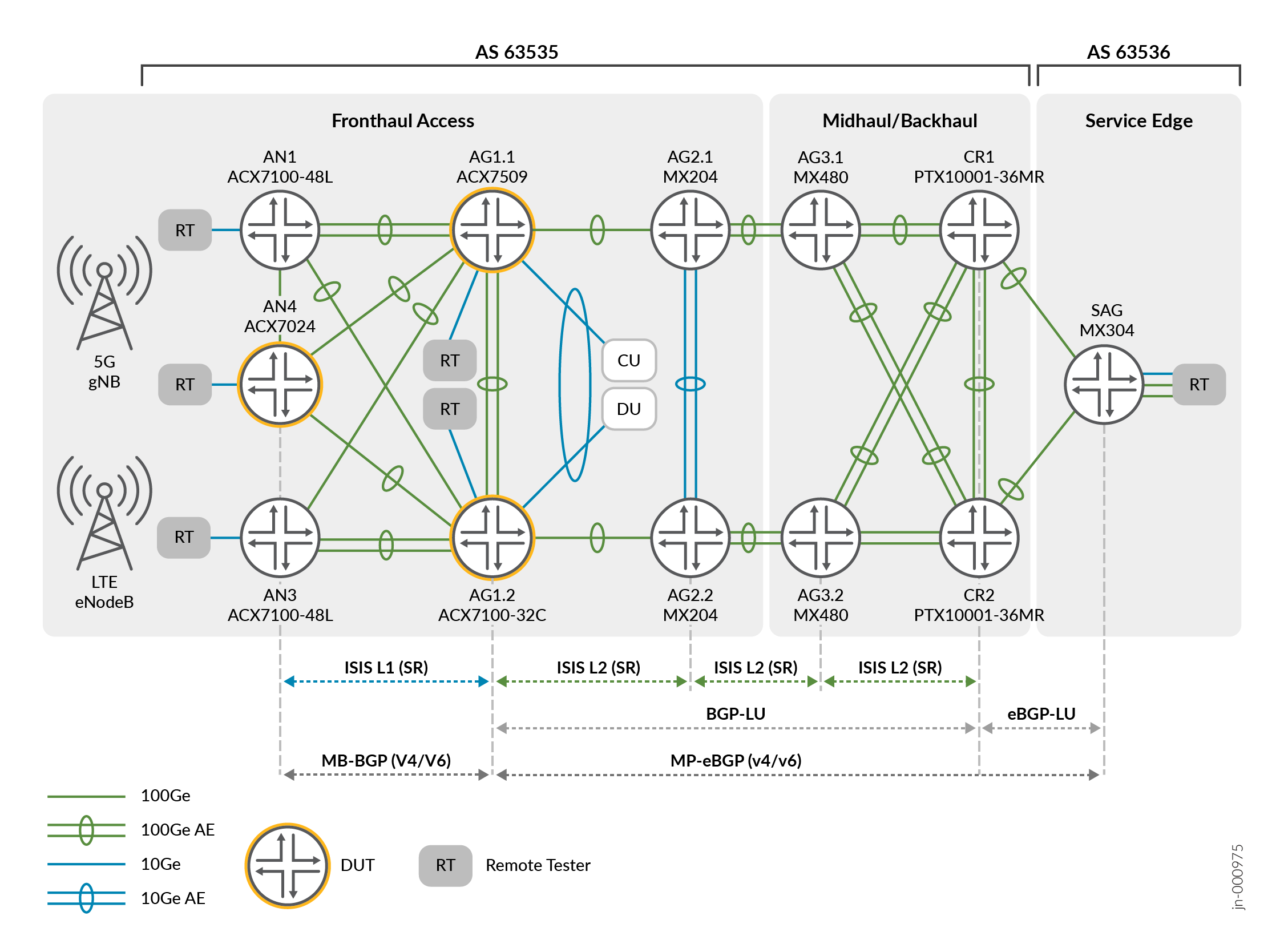
Topology involves Seamless MPLS with BGP-LU at border nodes and IS-IS SR underlay across multiple domains. Service overlay includes EVPN, L3VPN, VPLS, L2VPN, and L2Circuit. The end-to-end CoS model that this JVD uses might be extended or evolved to support architectures and use cases beyond what this document proposes.
Test Bed
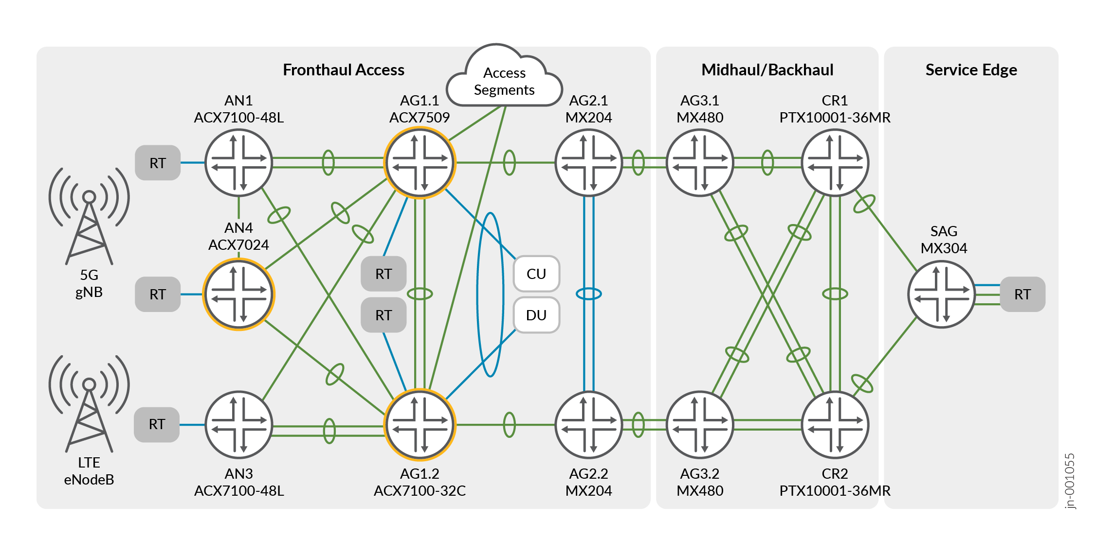
Figure 2 explains connectivity for building the physical 5G fronthaul CoS LLQ JVD infrastructure. The fronthaul segment leverages a spine-and-leaf topology, enabling connections between access nodes supporting cell site router (CSR) functionality to pre-aggregation nodes supporting hub site router (HSR) functions. The access segment leverages 100GbE speeds for the proposed topology, supporting up to 400GbE port speeds. CSR aggregates O-RU traffic supporting 5G, including legacy 4G workloads. The selected access nodes for the CSR role include the ACX7024 (AN4) and ACX7100-48L (AN1, AN3) platforms. HSR aggregates traffic from multiple CSRs, including additional emulated access segments and supports connectivity into the O-DU and O-CU relative to the functional split model. The selected aggregation nodes for the HSR role include the ACX7509 (AG1.1) and the ACX7100-32C (AG1.2). Additional helper nodes build out the aggregation and core segments with the MX204 (AG2), MX480 (AG3), and PTX10001-36MR (CR1, CR2) devices. Finally, the MX304 platform supports the Services Aggregation Gateway (SAG) role.

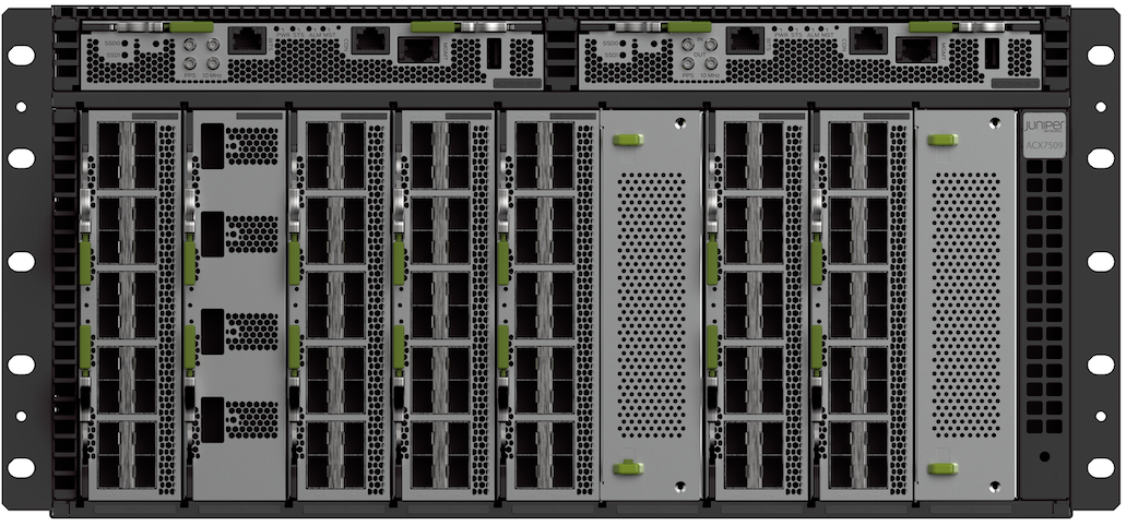
Platforms and Devices Under Test (DUT)
To review the software versions and platforms on which this JVD was validated by Juniper Networks, see the Validated Platforms and Software section in this document.