Solution QoS Architecture and Design
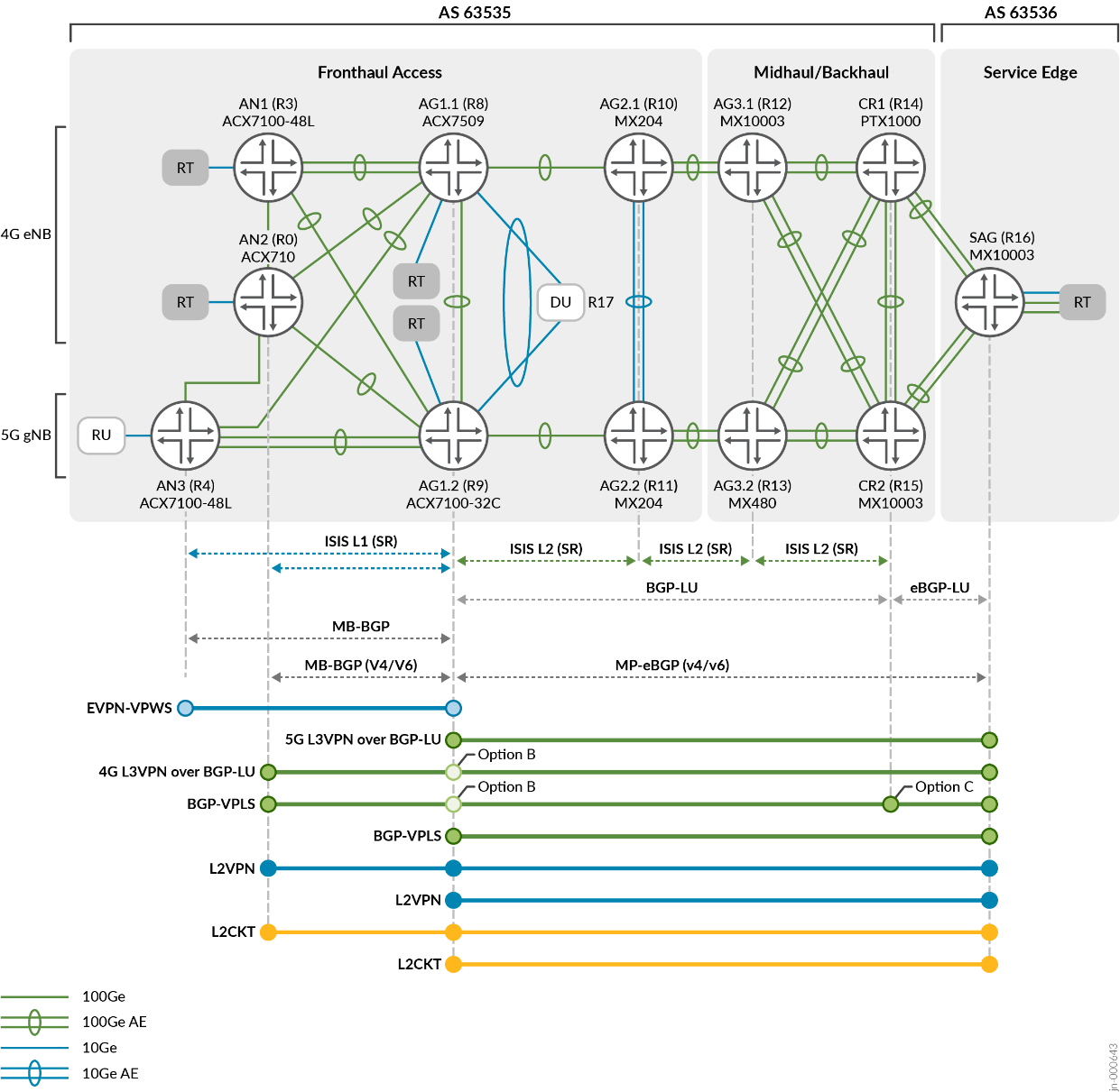
The test bed, illustrated in Figure 1, emulates a Seamless SR-MPLS architecture for a MBH with four layers of transport infrastructure: Access, Pre-Aggregation, Aggregation, and Core. In this setup, the 5G Fronthaul segment uses a spine-leaf access topology with redundant HSR (AG1.1/1.2) to support it. This configuration combines the roles of 4G Pre-Aggregation and 5G HSR. The Pre-Aggregation AG1 nodes provide O-DU connectivity and include additional emulated access insertion points (RT) to scale the environment. The Midhaul and Backhaul segments are represented by ring topologies, which include Aggregation and Core roles but are not the focus of the JVD.
Traffic Flows
The test network includes the following types of traffic flows:
- Layer 2 eCPRI between O-RU to O-DU traffic flows – 5G Fronthaul
- Layer 3 IP packet flows between 5G O-DU and CU/EPC – 5G Midhaul and Backhaul
- Layer 3 IP packet flows between 4G CSR and EPC (SAG) – 4G L3-MBH
- Layer 2 flows between CSR (AN) to EPC (SAG) – 4G L2-MBH
- Layer 2 Midhaul flows emulating additional attachment segments – 4G Midhaul and Backhaul
Segment Routing
Segment Routing MPLS is used as the underlying technology, which spans across multiple ISIS domains and inter-AS connections. The access nodes are placed within an ISIS L1 domain, establishing adjacencies with L1/L2 HSR nodes. The L2 domain extends from the aggregation to the core segments of the network. To achieve seamless SR-MPLS connectivity, BGP Labeled Unicast (BGP-LU) is enabled at the border nodes.
Route Reflectors
To handle the increased network scale and facilitate continued network growth, two sets of route reflectors are used at CR1 and CR2, primarily serving the westward HSR (AG1) clients. AG1.1/AG1.2 act as redundant route reflectors specifically for the access Fronthaul segment. Inter-AS Option-B solutions are supported through Multi-Protocol BGP peering between the Services Aggregation Gateway router (SAG) and the HSR (AG1).
Overlay Services
The overlay services utilize different combinations of VLAN operations, as shown in Table 3. These operations are applied to each Layer 2 service type defined in this JVD, including EVPN, L2Circuit, VPLS, and L2VPN. Flow Aware Transport Pseudowire Label (FAT-PW) is supported, starting with the Junos OS Evolved 22.3R1, for L2Circuit and L2VPN services, and is included in this JVD. Ethernet OAM with performance monitoring is enabled for EVPN Fronthaul and VPLS MBH services, ensuring effective monitoring of the network performance. Additionally, L3VPN services incorporate IPv6 tunnelling to validate 6vPE functionality.
5G QoS Identifier (5QI) Model
In 4G LTE networks, the QoS model is based on bearers. A bearer represents a logical connection between the user equipment (UE) and the network, and each bearer is associated with a specific QoS Class Identifier (QCI). The QCI determines the characteristics and priority of traffic flows within that bearer. The 4G LTE QCI model focusses on providing different levels of service based on predefined QCI values, which are standardized and mapped to specific QoS parameters such as packet delay, packet loss, and throughput.
In contrast, 5G networks introduce a flow-based QoS model using the concept of QoS Identifiers (5QIs). In this model, QoS is associated with individual data flows within the network. A flow represents a specific communication path or data stream between the UE and the network. Each flow is assigned a unique 5QI value that indicates the required QoS parameters for that flow, such as latency, reliability, and throughput.
The flow-based 5G QoS model provides more granular control and flexibility compared to the bearer-based 4G LTE QCI model. Instead of assigning a single QoS value to an entire bearer, 5G allows for different flows within the same bearer to have their own individual QoS requirements. This enables more fine-grained QoS management, allowing different applications and services to receive tailored treatment based on their specific needs. It also enables the network to dynamically adjust QoS parameters for individual flows, optimizing resource allocation and providing a better user experience.
When transitioning from the 4G LTE QCI model to the 5G QoS Identifier (5QI) model, there are some similarities in how we define and handle traffic. However, in 5G, we introduce new categories specifically for flows that require very low delay and high bandwidth. These are crucial for user and control traffic streams between O-RU and O-DU in the 5G Fronthaul segment.
5G incorporates several new delay-critical Guaranteed Bit Rate (GBR) flow categories. In the 5G Fronthaul segment, eCPRI based flows define the user and control traffic streams between O-RU and O-DU. These traffic characteristics require high bandwidth and extremely low delay. All devices in the access topology must assign the highest priority to this traffic type. This means that Service Providers may need to rethink their existing Class of Service designs where the highest priority queues were typically reserved for voice or video traffic.
The O-RAN 5QI/QCI Exemplary Grouping model, shown in Figure 2 and defined in O-RAN [O-RAN.WG9.XPSAAS-v02.00], groups common QCI and 5CI QoS flow characteristics into four exemplary groups based on delay budget.
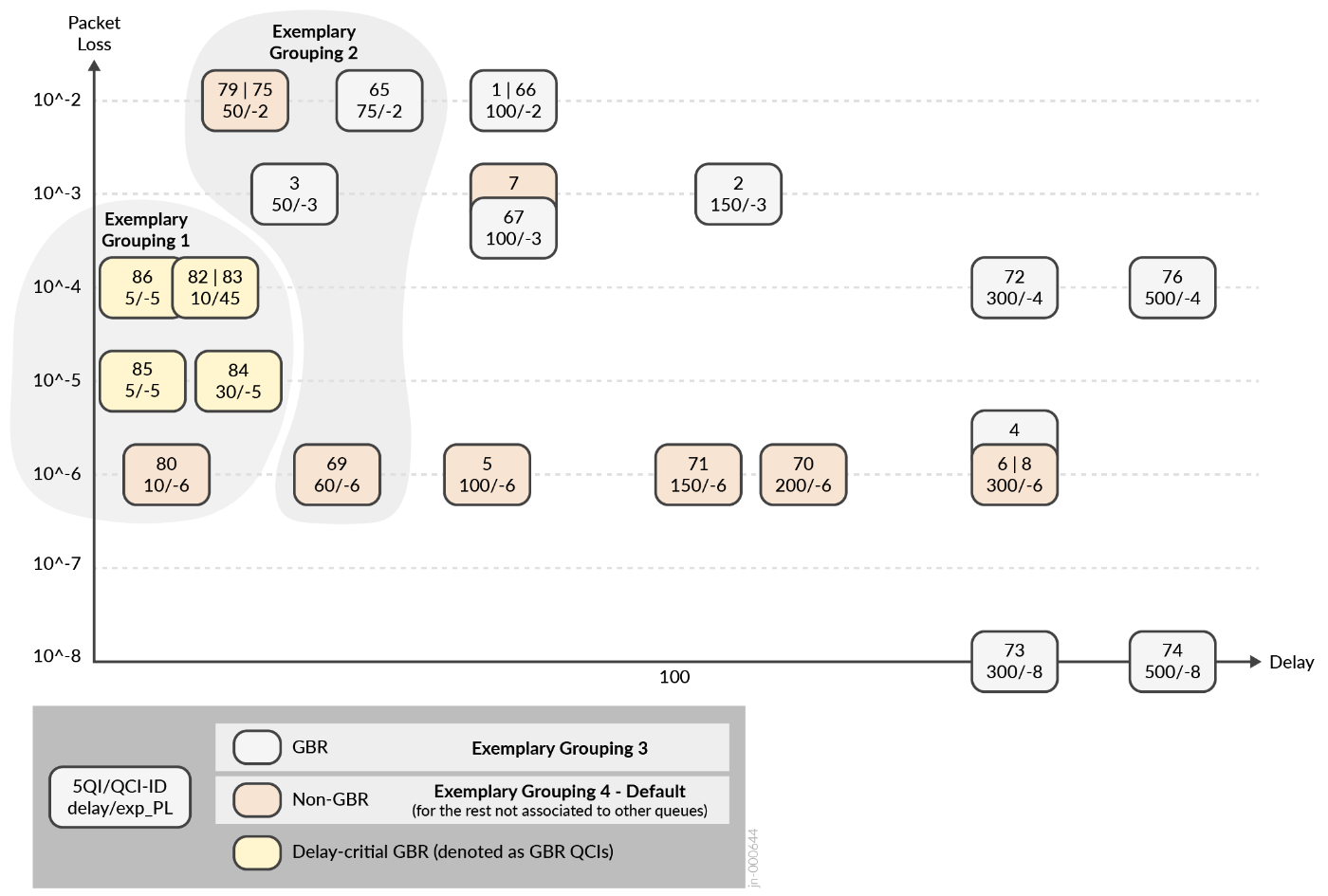
QoS schemas vary between mobile operators. This JVD doesn't endorse any specific design as the recommended approach.
A major objective is to examine predictable behaviors in terms of how critical and non-critical traffic flows are handled across services in the 5G xHaul network. The implementation of QoS should exhibit deterministic functionality. The transport architecture must prove capable to support the adaptation of existing and emerging mobile applications, preserving delay budget integrity while guaranteeing traffic priorities.
For more information about the specific latency and delay budgets considered for this validation, reach out to your Juniper Networks representative.
O-RAN/3GPP proposes two common QoS profiles to accommodate transport network requirements. In Profile A (Figure 3), a single priority queue is defined for handling ultra-low latency flows such as PTP and eCPRI. This queue is serviced ahead of all other queues. Lower priority queues are then serviced as weighted fair queuing (WFQ) round robin.
The Profile B model uses a hierarchy of queue priorities: high, medium, and low. These priority queues support preemption to minimize packet delay variations (PDV) and prioritize critical flows that require low latency. Specifically, the queue assigned for eCPRI traffic needs to have the ability to interrupt or take priority over other queues.
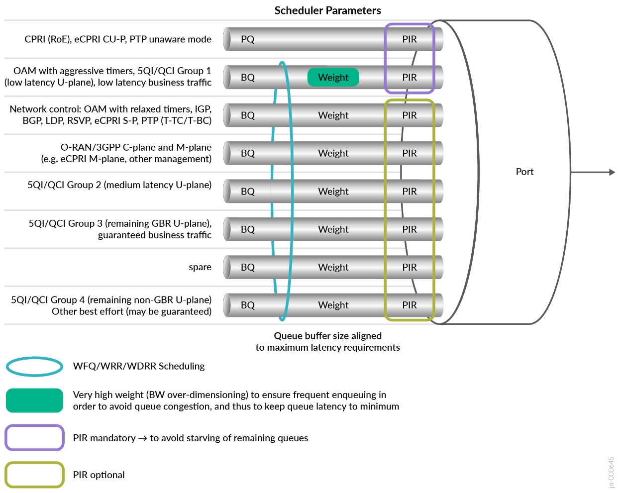
ACX Metro Routers support multiple strict-high (SH) or low priority queues. Strict-high queues are serviced as round-robin without the ability to preempt another priority queue. Profile A is selected for this JVD, reserving a strict-high queue for ultra-low latency between RU and DU.
Class of Service Building Blocks
Quality of Service (QoS) governs how traffic is forwarded, stored, or dropped in conjunction with mechanisms to manage and avoid congestion, which includes the basic building blocks:
- Classification
- Scheduling and Queuing
- Rewriting
- Shaping & Rate Limiting
QoS models differ between operators based on unique traffic profiles and characteristics. For the solution architecture, a realistic CoS model is created based on a pseudo customer, shown in Table 1. For more details on the CoS model leveraged in this JVD, contact your Juniper Networks representative.
| Forwarding Classes | Scheduling Parameters | Classification & Rewrite | Traffic Profile | ||||||||
|---|---|---|---|---|---|---|---|---|---|---|---|
| Queue | Queue Priority | Transmit rate | Buffer size | 802.1p | DSCP | MPLS EXP | Packet Loss Priority | Resource Type | Traffic Type | QCI/5CI Mapping | |
| Business | 5 | Low | 20% | 20% | 4 |
CS4, AF4x |
4 | Low | GBR | Guaranteed U-Plane Business Conversational Real Time Gaming/Video |
QCI1-4,6 QCI65-67 |
| Network Control | 4 | Low | 5% | 2% |
7 6 |
CS7 CS6 |
7 6 |
Low | GBR | Protocol, Timing | QCI82-90 |
| Real Time | 2 | Strict High |
40% Shaped |
30% | 5 |
CS5 EF |
5 | Low | Delay-Critical GBR | eCPRI | CPRI QCI82-90 |
| Signaling & OAM | 3 | Low | 5% | 2% | 3 |
CS3, AF3x |
3 | Low | Non-GBR | Signaling & OAM | QCI5 |
| Medium | 1 | Low | 20% | 20% | 2 |
CS2, AF2x |
2 | High | Non-GBR | Streaming Interactive | QCI4, 6-8 |
| Best Effort | 0 | Low | Remainder | Remainder |
1 0 |
CS1, AF1x RF |
1 0 |
Low High |
Non-GBR | Background | QCI9 |
The solution architecture includes two styles of ingress classification: fixed and behavior aggregate. Fixed classification is context-based where all traffic arriving on a specific interface is mapped into one forwarding class. Behavior Aggregate is packet-based where flows were pre-marked with Layer 3 DSCP, Layer 2 802.1Q Priority Code Points (PCP) or MPLS EXP.
O-RAN/3GPP proposes a minimum of six queues and maximum of eight queues per interface. All platforms in this solution architecture support eight queues. Six queues and associated forwarding classes are used to accommodate the traffic scheme requirements. In supporting Profile-A, only one strict-high queue is used, which is shaped (PIR) to prevent starving low priority queues. All other queues are configured as low priority and serviced as weighted fair queuing (WFQ) round robin, based on the designated transmit-rate.
At egress, DSCP, 802.1p or EXP codepoints and loss priorities (PLP) are rewritten based on the assigned forwarding class and rewrite-rule instruction. ACX Metro Routers support rewriting the outer tag by default. Generally, providers are required to preserve inner (C-TAG) 802.1p bits and transmitted transparently, without any changes or modifications.
Service Carve Out
As a best practice, ultra-low latency services (eCPRI) are assigned the highest priority. The treatment of MBH applications varies. The solution architecture uses priority mappings, grouped by service type. Refer to Table 2.
| Service | Traffic Type | Forwarding Class | Classifier Type | Priority |
|---|---|---|---|---|
| EVPN-VPWS | Delay-Critical GBR (eCPRI) | Realtime | Fixed | Strict High |
| L2Circuit | Non-GBR wholesale user plane | Best Effort | Fixed | Low |
| L2VPN | 4G/5G medium user plane | Best Effort/Medium | Behavior Aggregate | Low |
| BGP-VPLS | Non-GBR/GBR user plane | Best Effort/Business | Behavior Aggregate | Low |
| L3VPN | C/M/U-plane GBR/non-GBR | BE/MED/SIG-OAM/Business | Behavior Aggregate | Low |
VLAN Operations
ACX7000 series supports a more comprehensive set of VLAN manipulation operations compared to previous generation ACX routers. This JVD doesn’t include all possible operations, but does validate 60 VLAN combinations across L2Circuit, L2VPN, and EVPN services.
The test scenarios include the following VLAN operations:
- Untagged (UT) / Native VLAN
- Single-tag (ST) operations (pop, swap, push)
- Dual-tag (DT) operations (swap-swap, pop-swap/swap-push, pop-pop/push-push, swap-push/pop-swap)
- Rewrite PCP bits
- Preservation of PCP bits
- Classification of PCP bits and FC mapping
Table 3 shows the VLAN operations that we validated for EVPN-VPWS, L2Circuit and L2VPN services. Contact your Juniper Networks representative for comprehensive details about the VLAN operations that we validated, including configuration of each operation.
| VLAN Type | Outer Tag | Inner Tag | Input Operation | Output Operation | Classification | Rewrite |
|---|---|---|---|---|---|---|
| dual | 101 | 2201 | None | none | fixed | exp rewrite |
| dual | 102 | 2202 | Pop | push | fixed | exp rewrite |
| dual | 103 | 2203 | Swap | swap | fixed | exp rewrite |
| dual | 104 | 2204 | swap-swap | swap-swap | fixed | exp rewrite |
| dual | 105 | 2205 | pop-swap | swap-push | fixed | exp rewrite |
| dual | 106 | 2206 | pop-pop | push-push | fixed | exp rewrite |
| single | 107 | -- | Push | pop | fixed | exp rewrite |
| single | 108 | -- | Swap | swap | fixed | exp rewrite |
| single | 109 | -- | Pop | push | fixed | exp rewrite |
| single | 110 | -- | swap-push | pop-swap | fixed | exp rewrite |
| dual | 101 | 2201 | None | none | BA (exp) | 802.1p rewrite |
| dual | 102 | 2202 | Pop | push | BA (exp) | 802.1p rewrite |
| dual | 103 | 2203 | Swap | swap | BA (exp) | 802.1p rewrite |
| dual | 104 | 2204 | swap-swap | swap-swap | BA (exp) | 802.1p rewrite |
| dual | 105 | 2205 | pop-swap | swap-push | BA (exp) | 802.1p rewrite |
| dual | 106 | 2206 | pop-pop | push-push | BA (exp) | 802.1p rewrite |
| single | 107 | -- | Push | pop | BA (exp) | 802.1p rewrite |
| single | 108 | -- | Swap | swap | BA (exp) | 802.1p rewrite |
| single | 109 | -- | Pop | push | BA (exp) | 802.1p rewrite |
| single | 110 | -- | swap-push | pop-swap | BA (exp) | 802.1p rewrite |
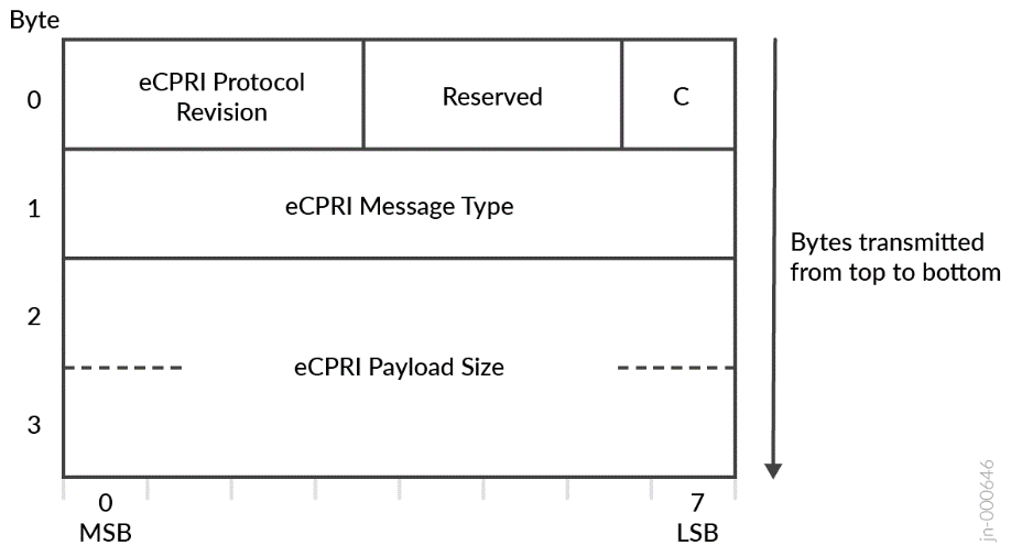
O-RAN and eCPRI Emulation
The O-RAN and eCPRI test scenarios included several functional permutations with emulated O-DU and Remote Radio Unit (RRU). Innovative steps are taken to validate not only performance, but assurance of 5G eCPRI communication, U-Plane message type behaviors, and O-RAN Conformance. These steps ensure the featured DUTs are correctly and consistently transporting these critical 5G services.
Results are further evolved across multiple topologies to capture a range of DUT performance characteristics in non-congested and congested scenarios. Note that this part of validation was not integrated into regression cycles and not reported in this JVD. If you are interested in details of test methodology and results for eCPRI emulation test series, please contact your Juniper Networks representative.
Here is the summary of ORAN and eCPRI test scenarios:
- eCPRI O-RAN Emulation: Leverages a standards IQ Sample file to generate flows.
- O-RAN Conformance: Analyzes messages for conformance to O-RAN specification.
- Crafted eCPRI O-RAN: Produces variable eCPRI payload for comparing latency performance.
- eCPRI Services Validation: Emulates User Plane messages, performing functional and integrity analysis.
- eCPRI Remote Memory Access (Type 4) : Performs read or write from/to a specific memory address on the opposite eCPRI node and validates expected success/failure conditions.
- eCPRI Delay Measurement Message (Type 5): Estimates one-way delay between two eCPRI ports.
- eCPRI Remote Reset Message (Type 6): One eCPRI node requests a reset of another node. Validates expected sender/receiver operations.
- eCPRI Event Indication Message (Type 7): Either side of the protocol indicates to the other an event has occurred. An event is either a raised or ceased fault or a notification. Validation confirms events raised as expected.
Contact your Juniper Networks representative for comprehensive test results.