Troubleshooting Layer 3 VPNs
Diagnosing Common Layer 3 VPN Problems
Problem
Description
To troubleshoot problems in the Layer 3 VPN configuration, start at one end of the VPN (the local customer edge [CE] router) and follow the routes to the other end of the VPN (the remote CE router).
Solution
The following troubleshooting steps should help you diagnose common problems:
If you configured a routing protocol between the local provider edge (PE) and CE routers, check that the peering and adjacency are fully operational. When you do this, be sure to specify the name of the routing instance. For example, to check OSPF adjacencies, enter the
show ospf neighbor instance routing-instance-namecommand on the PE router.If the peering and adjacency are not fully operational, check the routing protocol configuration on the CE router and check the routing protocol configuration for the associated VPN routing instance on the PE router.
Check that the local CE and PE routers can ping each other.
To check that the local CE router can ping the VPN interface on the local PE router, use a
pingcommand in the following format, specifying the IP address or name of the PE router:user@host> ping (ip-address | host-name)
To check that the local PE router can ping the CE router, use a
pingcommand in the following format, specifying the IP address or name of the CE router, the name of the interface used for the VPN, and the source IP address (the local address) in outgoing echo request packets:user@host> ping ip-address interface interface local echo-address
Often, the peering or adjacency between the local CE and local PE routers must come up before a
pingcommand is successful. To check that a link is operational in a lab setting, remove the interface from the VPN routing and forwarding (VRF) by deleting theinterfacestatement from the[edit routing-instance routing-instance-name]hierarchy level and recommitting the configuration. Doing this removes the interface from the VPN. Then try the ping command again. If the command is successful, configure the interface back into the VPN and check the routing protocol configuration on the local CE and PE routers again.On the local PE router, check that the routes from the local CE router are in the VRF table (routing-instance-name.inet.0):
user@host> show route table routing-instance-name.inet.0 <detail>
The following example shows the routing table entries. Here, the loopback address of the CE router is
10.255.14.155/32and the routing protocol between the PE and CE routers is BGP. The entry looks like any ordinary BGP announcement.10.255.14.155/32 (1 entry, 1 announced) *BGP Preference: 170/-101 Nexthop: 192.168.197.141 via fe-1/0/0.0, selected State: <Active Ext> Peer AS: 1 Age: 45:46 Task: BGP_1.192.168.197.141+179 Announcement bits (2): 0-BGP.0.0.0.0+179 1-KRT AS path: 1 I Localpref: 100 Router ID: 10.255.14.155If the routes from the local CE router are not present in the VRF routing table, check that the CE router is advertising routes to the PE router. If static routing is used between the CE and PE routers, make sure the proper static routes are configured.
On a remote PE router, check that the routes from the local CE router are present in the bgp.l3vpn.0 routing table:
user@host> show route table bgp.l3vpn.0 extensive
10.255.14.175:3:10.255.14.155/32 (1 entry, 0 announced)
        *BGP    Preference: 170/-101
                Route Distinguisher: 10.255.14.175:3
                Source: 10.255.14.175
                Nexthop: 192.168.192.1 via fe-1/1/2.0, selected
                label-switched-path vpn07-vpn05
                Push 100004, Push 100005(top)
                State: <Active Int Ext>
                Local AS:    69 Peer AS:    69
                Age: 15:27      Metric2: 338
                Task: BGP_69.10.255.14.175+179
                AS path: 1 I
                Communities: target:69:100
                BGP next hop: 10.255.14.175
                Localpref: 100
                Router ID: 10.255.14.175
                Secondary tables: VPN-A.inet.0
The output of the
show route table bgp.l3vpn.0 extensivecommand contains the following information specific to the VPN:In the prefix name (the first line of the output), the route distinguisher is added to the route prefix of the local CE router. Because the route distinguisher is unique within the Internet, the concatenation of the route distinguisher and IP prefix provides unique VPN-IP version 4 (IPv4) routing entries.
The
Route Distinguisherfield lists the route distinguisher separately from the VPN-IPv4 address.The
label-switched-pathfield shows the name of the label-switched path (LSP) used to carry the VPN traffic.The
Pushfield shows both labels being carried in the VPN-IPv4 packet. The first label is the inner label, which is the VPN label that was assigned by the PE router. The second label is the outer label, which is an RSVP label.The
Communitiesfield lists the target community.The
Secondary tablesfield lists other routing tables on this router into which this route has been installed.
If routes from the local CE router are not present in the bgp.l3vpn.0 routing table on the remote PE router, do the following:
Check the VRF import filter on the remote PE router, which is configured in the
vrf-importstatement. (On the local PE router, you check the VRF export filter, which is configured with thevrf-exportstatement.)Check that there is an operational LSP or an LDP path between the PE routers. To do this, check that the IBGP next-hop addresses are in the inet.3 table.
Check that the IBGP session between the PE routers is established and configured properly.
Check for “hidden” routes, which usually means that routes were not labeled properly. To do this, use the
show route table bgp.l3vpn.0 hiddencommand.Check that the inner label matches the inner VPN label that is assigned by the local PE router. To do this, use the
show route table mplscommand.
The following example shows the output of this command on the remote PE router. Here, the inner label is
100004.... Push 100004, Push 10005 (top)
The following example shows the output of this command on the local PE router, which shows that the inner label of
100004matches the inner label on the remote PE router:... 100004 *[VPN/7] 06:56:25, metric 1 > to 192.168.197.141 via fe-1/0/0.0, Pop
On the remote PE router, check that the routes from the local CE router are present in the VRF table (routing-instance-name.inet.0):
user@host> show route table routing-instance-name.inet.0 detail
10.255.14.155/32 (1 entry, 1 announced)
        *BGP    Preference: 170/-101
                Route Distinguisher: 10.255.14.175:3
                Source: 10.255.14.175
                Nexthop: 192.168.192.1 via fe-1/1/2.0, selected
                label-switched-path vpn07-vpn05
                Push 100004, Push 100005(top)
                State: <Secondary Active Int Ext>
                Local AS:    69 Peer AS:    69
                Age: 1:16:22    Metric2: 338
                Task: BGP_69.10.255.14.175+179
                Announcement bits (2): 1-KRT 2-VPN-A-RIP
                AS path: 1 I
                Communities: target:69:100
                BGP next hop: 10.255.14.175
                Localpref: 100
                Router ID: 10.255.14.175
                Primary Routing Table bgp.l3vpn.0
In this routing table, the route distinguisher is no longer prepended to the prefix. The last line,
Primary Routing
Table
, lists the table from which this route was learned.If the routes are not present in this routing table, but were present in the bgp.l3vpn.0 routing table on the local CE router, the routes might have not passed the VRF import policy on the remote PE router.
If a VPN-IPv4 route matches no
vrf-importpolicy, the route does not show up in the bgp.l3vpn table at all and hence is not present in the VRF table. If this occurs, it might indicate that on the PE router, you have configured anothervrf-importstatement on another VPN (with a common target), and the routes show up in the bgp.l3vpn.0 table, but are imported into the wrong VPN.On the remote CE router, check that the routes from the local CE router are present in the routing table (inet.0):
user@host> show route
If the routes are not present, check the routing protocol configuration between the remote PE and CE routers, and make sure that peers and adjacencies (or static routes) between the PE and CE routers are correct.
If you determine that routes originated from the local CE router are correct, check the routes originated from the remote CE router by repeating this procedure.
Example: Troubleshooting Layer 3 VPNs
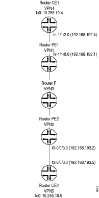
This example shows how to use the ping command to check the accessibility of various routers in a VPN topology,
and how to use the traceroute command to check the path
that packets travel between the VPN routers.
- Requirements
- Overview
- Pinging the CE Router from Another CE Router
- Pinging the Remote PE and CE Routers from the Local CE Router
- Pinging a CE Router from a Multiaccess Interface
- Pinging the Directly Connected PE Routers from the CE Routers
- Pinging the Directly Connected CE Routers from the PE Routers
- Pinging the Remote CE Router from the Local PE Router
- Troubleshooting Inconsistently Advertised Routes from Gigabit Ethernet Interfaces
Requirements
This example uses the following hardware and software components:
-
M Series routers
-
Junos OS Release 10.0R1 and later
Overview
Topology
The topology shown in Figure 1 illustrates the network used in this example to demonstrate how to employ the ping and traceroute commands to test connectivity between the routers participating in a Layer 3 VPN.
Pinging the CE Router from Another CE Router
Procedure
Step-by-Step Procedure
The following describes how to use the ping and traceroute commands to troubleshoot Layer 3 VPN topologies.
You can ping one CE router from the other by specifying the other
CE router’s loopback address as the IP address in the ping command. This ping command succeeds if the loopback addresses
have been announced by the CE routers to their directly connected
PE routers. The success of these ping commands also means
that Router CE1 can ping any network devices beyond Router CE2, and
vice versa. Figure 1 shows the topology referenced
in the following steps:
-
Ping Router CE2 (VPN5) from Router CE1 (VPN4):
user@vpn4> ping 10.255.10.5 local 10.255.10.4 count 3
PING 10.255.10.5 (10.255.10.5): 56 data bytes
64 bytes from 10.255.10.5: icmp_seq=0 ttl=253 time=1.086 ms
64 bytes from 10.255.10.5: icmp_seq=1 ttl=253 time=0.998 ms
64 bytes from 10.255.10.5: icmp_seq=2 ttl=253 time=1.140 ms
--- 10.255.10.5 ping statistics ---
3 packets transmitted, 3 packets received, 0% packet loss
round-trip min/avg/max/stddev = 0.998/1.075/1.140/0.059 ms
-
To determine the path from Router CE1’s loopback interface to Router CE2’s loopback interface, use the
traceroutecommand:user@vpn4> traceroute 10.255.10.5 source 10.255.10.4 traceroute to 10.255.10.5 (10.255.10.5) from 10.255.10.4, 30 hops max, 40 byte packets 1 vpn1-fe-110.isp-core.net (192.168.192.1) 0.680 ms 0.491 ms 0.456 ms 2 vpn2-t3-001.isp-core.net (192.168.192.110) 0.857 ms 0.766 ms 0.754 ms MPLS Label=100005 CoS=0 TTL=1 S=1 3 vpn5.isp-core.net (10.255.10.5) 0.825 ms 0.886 ms 0.732 ms -
When you use the
traceroutecommand to examine the path used by a Layer 3 VPN, the provider (P) routers in the service provider’s network are not displayed. As shown above, the jump from Router VPN1 to Router VPN2 is displayed as a single hop. The P router (VPN3) shown in Figure 1 is not displayed. -
Ping Router CE1 (VPN4) from Router CE2 (VPN5):
user@vpn5> ping 10.255.10.4 local 10.255.10.5 count 3
PING 10.255.10.4 (10.255.10.4): 56 data bytes
64 bytes from 10.255.10.4: icmp_seq=0 ttl=253 time=1.042 ms
64 bytes from 10.255.10.4: icmp_seq=1 ttl=253 time=0.998 ms
64 bytes from 10.255.10.4: icmp_seq=2 ttl=253 time=0.954 ms
--- 10.255.10.4 ping statistics ---
3 packets transmitted, 3 packets received, 0% packet loss
round-trip min/avg/max/stddev = 0.954/0.998/1.042/0.036 ms
-
To determine the path from Router CE2 to Router CE1, use the
traceroutecommand:user@vpn5> traceroute 10.255.10.4 source 10.255.10.5 traceroute to 10.255.10.4 (10.255.10.4) from 10.255.10.5, 30 hops max, 40 byte packets 1 vpn-08-t3-003.isp-core.net (192.168.193.2) 0.686 ms 0.519 ms 0.548 ms 2 vpn1-so-100.isp-core.net (192.168.192.100) 0.918 ms 0.869 ms 0.859 ms MPLS Label=100021 CoS=0 TTL=1 S=1 3 vpn4.isp-core.net (10.255.10.4) 0.878 ms 0.760 ms 0.739 ms
Pinging the Remote PE and CE Routers from the Local CE Router
Procedure
Step-by-Step Procedure
From the local CE router, you can ping the VPN interfaces on the remote PE and CE routers, which are point-to-point interfaces. Figure 1 shows the topology referenced in the following examples:
-
Ping router CE2 from router CE1.
user@vpn4> ping 192.168.193.5 local 10.255.10.4 count 3
PING 192.168.193.5 (192.168.193.5): 56 data bytes
64 bytes from 192.168.193.5: icmp_seq=0 ttl=253 time=1.040 ms
64 bytes from 192.168.193.5: icmp_seq=1 ttl=253 time=0.891 ms
64 bytes from 192.168.193.5: icmp_seq=2 ttl=253 time=0.944 ms
--- 192.168.193.5 ping statistics ---
3 packets transmitted, 3 packets received, 0% packet loss
round-trip min/avg/max/stddev = 0.891/0.958/1.040/0.062 ms
-
To determine the path from Router CE1’s loopback interface to Router CE2’s directly connected interface, use the
traceroutecommand:user@vpn4> traceroute 192.168.193.5 source 10.255.10.4 traceroute to 192.168.193.5 (192.168.193.5) from 10.255.10.4, 30 hops max, 40 byte packets 1 vpn1-fe-110.isp-core.net (192.168.192.1) 0.669 ms 0.508 ms 0.457 ms 2 vpn2-t3-001.isp-core.net (192.168.192.110) 0.851 ms 0.769 ms 0.750 ms MPLS Label=100000 CoS=0 TTL=1 S=1 3 vpn5-t3-003.isp-core.net (192.168.193.5) 0.829 ms 0.838 ms 0.731 ms -
Ping Router PE2 (VPN2) from Router CE1 (VPN4). In this case, packets that originate at Router CE1 go to Router PE2, then to Router CE2, and back to Router PE2 before Router PE2 can respond to Internet Control Message Protocol (ICMP) requests. You can verify this by using the
traceroutecommand.user@vpn4> ping 192.168.193.2 local 10.255.10.4 count 3 PING 192.168.193.2 (192.168.193.2): 56 data bytes 64 bytes from 192.168.193.2: icmp_seq=0 ttl=254 time=1.080 ms 64 bytes from 192.168.193.2: icmp_seq=1 ttl=254 time=0.967 ms 64 bytes from 192.168.193.2: icmp_seq=2 ttl=254 time=0.983 ms --- 192.168.193.2 ping statistics --- 3 packets transmitted, 3 packets received, 0% packet loss round-trip min/avg/max/stddev = 0.967/1.010/1.080/0.050 ms
-
To determine the path from Router CE1 to Router PE2, use the
traceroutecommand:user@vpn4> traceroute 192.168.193.2 source 10.255.10.4 traceroute to 192.168.193.2 (192.168.193.2) from 10.255.10.4, 30 hops max, 40 byte packets 1 vpn1-fe-110.isp-core.net (192.168.192.1) 0.690 ms 0.490 ms 0.458 ms 2 vpn2-t3-003.isp-core.net (192.168.193.2) 0.846 ms 0.768 ms 0.749 ms MPLS Label=100000 CoS=0 TTL=1 S=1 3 vpn5-t3-003.isp-core.net (192.168.193.5) 0.643 ms 0.703 ms 0.600 ms 4 vpn-08-t3-003.isp-core.net (192.168.193.2) 0.810 ms 0.739 ms 0.729 ms
Pinging a CE Router from a Multiaccess Interface
Procedure
Step-by-Step Procedure
You cannot ping one CE router from the other if the VPN
interface is a multiaccess interface, such as the fe-1/1/2.0 interface on Router CE1. To ping Router CE1 from Router CE2,
you must either include the vrf-table-label statement at
the [edit routing-instances routing-instance-name] hierarchy level on Router PE1 or configure a static
route on Router PE1 to the VPN interface of Router CE1.
If you include the vrf-table-label statement to ping a
router, you cannot configure a static route.
-
If you configure a static route on Router PE1 to the VPN interface of Router CE1, its next hop must point to Router CE1 (at the
[edit routing-instance routing-instance-name]hierarchy level), and this route must be announced from Router PE1 to Router PE2 as shown in the following configuration:[edit] routing-instances { direct-multipoint { instance-type vrf; interface fe-1/1/0.0; route-distinguisher 69:1; vrf-import direct-import; vrf-export direct-export; routing-options { static { route 192.168.192.4/32 next-hop 192.168.192.4; } } protocols { bgp { group to-vpn4 { peer-as 1; neighbor 192.168.192.4; } } } } policy-options { policy-statement direct-export { term a { from protocol bgp; then { community add direct-comm; accept; } } term b { from { protocol static; route-filter 192.168.192.4/32 exact; } then { community add direct-comm; accept; } } term d { then reject; } } } } -
Now you can ping Router CE1 from Router CE2:
user@vpn5> ping 192.168.192.4 local 10.255.10.5 count 3
PING 192.168.192.4 (192.168.192.4): 56 data bytes
64 bytes from 192.168.192.4: icmp_seq=0 ttl=253 time=1.092 ms
64 bytes from 192.168.192.4: icmp_seq=1 ttl=253 time=1.019 ms
64 bytes from 192.168.192.4: icmp_seq=2 ttl=253 time=1.031 ms
--- 192.168.192.4 ping statistics ---
3 packets transmitted, 3 packets received, 0% packet loss
round-trip min/avg/max/stddev = 1.019/1.047/1.092/0.032 ms
-
To determine the path between these two interfaces, use the
traceroutecommand:user@vpn5> traceroute 192.168.192.4 source 10.255.10.5 traceroute to 192.168.192.4 (192.168.192.4) from 10.255.10.5, 30 hops max, 40 byte packets 1 vpn-08-t3003.isp-core.net (192.168.193.2) 0.678 ms 0.549 ms 0.494 ms 2 vpn1-so-100.isp-core.net (192.168.192.100) 0.873 ms 0.847 ms 0.844 ms MPLS Label=100021 CoS=0 TTL=1 S=1 3 vpn4-fe-112.isp-core.net (192.168.192.4) 0.825 ms 0.743 ms 0.764 ms
Pinging the Directly Connected PE Routers from the CE Routers
Procedure
Step-by-Step Procedure
From the loopback interfaces on the CE routers, you can ping the VPN interface on the directly connected PE router. Figure 1 shows the topology referenced in this procedure:
-
From the loopback interface on Router CE1 (VPN4), ping the VPN interface,
fe-1/1/0.0, on Router PE1:user@vpn4> ping 192.168.192.1 local 10.255.10.4 count 3 PING 192.168.192.1 (192.168.192.1): 56 data bytes 64 bytes from 192.168.192.1: icmp_seq=0 ttl=255 time=0.885 ms 64 bytes from 192.168.192.1: icmp_seq=1 ttl=255 time=0.757 ms 64 bytes from 192.168.192.1: icmp_seq=2 ttl=255 time=0.734 ms --- 192.168.192.1 ping statistics --- 3 packets transmitted, 3 packets received, 0% packet loss round-trip min/avg/max/stddev = 0.734/0.792/0.885/0.066 ms
-
From the loopback interface on Router CE2 (VPN5), ping the VPN interface,
t3-0/0/3.0, on Router PE2:user@vpn5> ping 192.168.193.2 local 10.255.10.5 count 3 PING 192.168.193.2 (192.168.193.2): 56 data bytes 64 bytes from 192.168.193.2: icmp_seq=0 ttl=255 time=0.998 ms 64 bytes from 192.168.193.2: icmp_seq=1 ttl=255 time=0.834 ms 64 bytes from 192.168.193.2: icmp_seq=2 ttl=255 time=0.819 ms --- 192.168.193.2 ping statistics --- 3 packets transmitted, 3 packets received, 0% packet loss round-trip min/avg/max/stddev = 0.819/0.884/0.998/0.081 ms
-
To determine the path from the loopback interface on Router CE2 to the VPN interfaces on Router PE2, use the
traceroutecommand:user@vpn5> traceroute 192.168.193.2 source 10.255.10.5 traceroute to 192.168.193.2 (192.168.193.2) from 10.255.10.5, 30 hops max, 40 byte packets 1 vpn-08-t3003.isp-core.net (192.168.193.2) 0.852 ms 0.670 ms 0.656 ms
Pinging the Directly Connected CE Routers from the PE Routers
Procedure
Step-by-Step Procedure
From the VPN and loopback interfaces on the PE routers, you can ping the VPN interface on the directly connected CE router. Figure 1 shows the topology referenced in this procedure:
-
From the VPN interface on the PE router (router PE1), you can ping the VPN or loopback interface on the directly connected CE router (router CE1).
From the VPN interface on Router PE1 (VPN1), ping the VPN interface,
fe-1/1/0.0, on Router CE1:user@vpn1> ping 192.168.192.4 interface fe-1/1/0.0 local 192.168.192.1 count 3 PING 192.168.192.4 (192.168.192.4): 56 data bytes 64 bytes from 192.168.192.4: icmp_seq=0 ttl=255 time=0.866 ms 64 bytes from 192.168.192.4: icmp_seq=1 ttl=255 time=0.728 ms 64 bytes from 192.168.192.4: icmp_seq=2 ttl=255 time=0.753 ms --- 192.168.192.4 ping statistics --- 3 packets transmitted, 3 packets received, 0% packet loss round-trip min/avg/max/stddev = 0.728/0.782/0.866/0.060 ms
-
From the VPN interface on Router PE1 (VPN1), ping the loopback interface,
10.255.10.4, on Router CE1:user@vpn1> ping 10.255.10.4 interface fe-1/1/0.0 local 192.168.192.1 count 3 PING 10.255.10.4 (10.255.10.4): 56 data bytes 64 bytes from 10.255.10.4: icmp_seq=0 ttl=255 time=0.838 ms 64 bytes from 10.255.10.4: icmp_seq=1 ttl=255 time=0.760 ms 64 bytes from 10.255.10.4: icmp_seq=2 ttl=255 time=0.771 ms --- 10.255.10.4 ping statistics --- 3 packets transmitted, 3 packets received, 0% packet loss round-trip min/avg/max/stddev = 0.760/0.790/0.838/0.034 ms
-
To determine the path from the VPN interface on Router PE1 to the VPN and loopback interfaces on Router CE1, respectively, use the following
traceroutecommands:user@vpn1> traceroute 10.255.10.4 interface fe-1/1/0.0 source 192.168.192.1 traceroute to 10.255.10.4 (10.255.10.4) from 192.168.192.1, 30 hops max, 40 byte packets 1 vpn4.isp-core.net (10.255.10.4) 0.842 ms 0.659 ms 0.621 ms user@vpn1> traceroute 192.168.192.4 interface fe-1/1/0.0 source 192.168.192.1 traceroute to 192.168.192.4 (192.168.192.4) from 192.168.192.1, 30 hops max, 40 byte packets 1 vpn4-fe-112.isp-core.net (192.168.192.4) 0.810 ms 0.662 ms 0.640 ms
-
From the VPN interface on Router PE2 (VPN2), ping the VPN interface,
t3-0/0/3.0, on Router CE2:user@vpn2> ping 192.168.193.5 interface t3-0/0/3.0 local 192.168.193.2 count 3 PING 192.168.193.5 (192.168.193.5): 56 data bytes 64 bytes from 192.168.193.5: icmp_seq=0 ttl=255 time=0.852 ms 64 bytes from 192.168.193.5: icmp_seq=1 ttl=255 time=0.909 ms 64 bytes from 192.168.193.5: icmp_seq=2 ttl=255 time=0.793 ms --- 192.168.193.5 ping statistics --- 3 packets transmitted, 3 packets received, 0% packet loss round-trip min/avg/max/stddev = 0.793/0.851/0.909/0.047 ms
-
From the VPN interface on Router PE2 (VPN2), ping the loopback interface,
10.255.10.5, on Router CE2:user@vpn2> ping 10.255.10.5 interface t3-0/0/3.0 local 192.168.193.2 count 3 PING 10.255.10.5 (10.255.10.5): 56 data bytes 64 bytes from 10.255.10.5: icmp_seq=0 ttl=255 time=0.914 ms 64 bytes from 10.255.10.5: icmp_seq=1 ttl=255 time=0.888 ms 64 bytes from 10.255.10.5: icmp_seq=2 ttl=255 time=1.066 ms --- 10.255.10.5 ping statistics --- 3 packets transmitted, 3 packets received, 0% packet loss round-trip min/avg/max/stddev = 0.888/0.956/1.066/0.079 ms
-
To determine the path from the VPN interface on Router PE2 to the VPN and loopback interfaces on Router CE2, respectively, use the following
traceroutecommands:user@vpn2> traceroute 10.255.10.5 interface t3-0/0/3.0 source 192.168.193.2 traceroute to 10.255.10.5 (10.255.10.5) from 192.168.193.2, 30 hops max, 40 byte packets 1 vpn5.isp-core.net (10.255.10.5) 1.009 ms 0.677 ms 0.633 ms user@vpn2> traceroute 192.168.193.5 interface t3-0/0/3.0 source 192.168.193.2 traceroute to 192.168.193.5 (192.168.193.5) from 192.168.193.2, 30 hops max, 40 byte packets 1 vpn5-t3-003.isp-core.net (192.168.193.5) 0.974 ms 0.665 ms 0.619 ms
Pinging the Remote CE Router from the Local PE Router
Procedure
Step-by-Step Procedure
The following procedure is effective for Layer 3 VPNs only. To ping a remote CE router from a local PE router in a Layer 3 VPN, you need to configure the following interfaces:
-
Configure a logical unit for the loopback interface.
To configure an additional logical unit on the loopback interface of the PE router, configure the
unitstatement at the[edit interfaces lo0]hierarchy level:[edit interfaces] lo0 { unit number { family inet { address address; } } } -
Configure the loopback interface for the Layer 3 VPN routing instance on the local PE router. You can associate one logical loopback interface with each Layer 3 VPN routing instance, enabling you to ping a specific routing instance on a router.
Specify the loopback interface you configured in Step 1 using the
interfacestatement at the[edit routing-instances routing-instance-name]hierarchy level:[edit routing-instances routing-instance-name] interface interface-name;
The
interface-nameis the logical unit on the loopback interface (for example,lo0.1). -
From the VPN interface on PE router, you can now ping the logical unit on the loopback interface on the remote CE router:
user@host> ping interface interface
                     host
Use
interfaceto specify the new logical unit on the loopback interface (for example,lo0.1). For more information about how to use theping interfacecommand, see the Junos Interfaces Command Reference.
Troubleshooting Inconsistently Advertised Routes from Gigabit Ethernet Interfaces
Procedure
Step-by-Step Procedure
For direct routes on a LAN in a Layer 3 VPN, the Junos OS attempts to locate a CE router that can be designated as the next hop. If this cannot be done, advertised routes from Gigabit Ethernet interfaces are dropped.
In such instances:
-
Use the
staticstatement at the[edit routing-options]or[edit logical-systems logical-system-name routing-options]hierarchy levels in the VRF routing instance to a CE router on the LAN subnet, configuring the CE router as the next hop. All traffic to directly destinations on this LAN will go to the CE router. You can add two static routes to two CE routers on the LAN for redundancy. -
Configure the
vrf-table-labelstatement at the[edit routing-instances routing-instance-name]hierarchy levels to map the inner label of a packet to a specific VRF routing table. This allows the examination of the encapsulated IP header to force IP lookups on the VRF routing instance for all traffic.Note:The
vrf-table-labelstatement is not available for every core-facing interface; for example, channelized interfaces are not supported. See Filtering Packets in Layer 3 VPNs Based on IP Headers for information about support for thevrf-table-labelstatement over Ethernet and SONET/SDH interfaces.
Example: Diagnosing Networking Problems Related to Layer 3 VPNs by Disabling TTL Decrementing
This example shows how to disable TTL decrementing in a single VRF routing instance in a Layer 3 VPN scenario.
Requirements
Before you begin:
-
Configure the router interfaces. See the Network Interfaces Configuration Guide.
Overview
To diagnose networking problems related to VPNs, it can be useful to disable normal time-to-live (TTL) decrementing. The IP header includes a TTL field that serves as a hop counter. At every routed hop, the TTL is decremented by one; if the TTL reaches zero before the packet reaches its destination, the packet is discarded and (optionally) an ICMP TTL exceeded message is sent to the source. MPLS labels also have a TTL field. MPLS routers copy the TTL of an IP packet when it enters a label-switched path (LSP). An IP packet with a TTL of 27 receives an MPLS label with a TTL of 27. Junos OS decrements the MPLS TTL of an MPLS-encapsulated packet in place of the IP TTL, at every label-switched hop. Because the MPLS TTL is copied (or propagated) from the IP TTL, a traceroute lists every hop in the path, be it routed or label-switched. When the packet exits the LSP, the decremented MPLS TTL is propagated back into the IP TTL field.
By default, TTL propagation is enabled. The global no-propagate-ttl statement disables TTL propagation at the router level and affects
all RSVP-signalled or LDP-signalled LSPs. When a router acts as an
ingress router for an LSP and the router configuration includes the no-propagate-ttl statement, the router pushes an MPLS header
with a TTL value of 255, regardless of the IP packet TTL. When a router
acts as the penultimate router, it pops the MPLS header without propagating
the MPLS TTL into the IP packet. Thus the IP packet TTL value is preserved,
regardless of the hop count of the LSP.
Instead of configuring TTL propagation behavior at the router level, you can configure the behavior for the routes in a VRF routing instance. This example shows how to disable TTL propagation for the routes in a single VRF routing instance instead of at the global router level.
The per-VRF configuration takes precedence over the global router
configuration. If you disable TTL propagation on the router and explicitly
enable TTL propagation for a single VRF routing instance, TTL propagation
is in effect for that routing instance. To explicitly enable TTL propagation
on a VRF routing instance, include the vrf-propagate-ttl statement in the routing instance.
When you change the TTL propagation behavior, old next hops for VRF routes are deleted from the inet.3 routing table and new next hops are added.
You need only configure the vrf-propagate-ttl or no-vrf-propagate-ttl statement on the ingress routers.
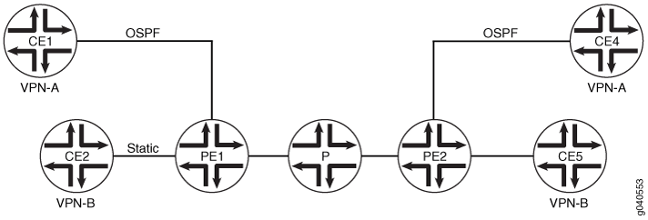
Topology Diagram
Figure 2 shows the topology
used in this example. Router PE1 and Router PE2 have two VPNs---VPN-A
and VPN-B. Devices CE1 and CE4 belong to VPN-A. Devices CE2 and CE5
belong to VPN-B. In this example, Router PE1 has TTL propagation disabled
on VPN-A but not on VPN-B. Packets received by PE1 on the interface
connected to CE1 have TTL propagation disabled. This example shows
the configuration on Router PE1. You do not need to include the no-vrf-propagate-ttl statement on the egress router (PE2).
Configuration
Procedure
CLI Quick Configuration
To quickly disable TTL propagation in a VRF routing instance, copy the following commands and paste the commands into the CLI.
[edit]
set interfaces lo0 unit 0 family inet address 10.255.179.45/32 primary
set protocols mpls interface all
set protocols bgp group ibgp type internal
set protocols bgp group ibgp local-address 10.255.179.45
set protocols bgp group ibgp family inet-vpn unicast
set protocols bgp group ibgp neighbor 10.255.179.71
set protocols ospf area 0.0.0.0 interface fe-1/1/2.0
set protocols ospf area 0.0.0.0 interface fxp0.0 disable
set protocols ospf area 0.0.0.0 interface lo0.0
set protocols ldp interface all
set policy-options policy-statement VPN-A-export term a from protocol ospf
set policy-options policy-statement VPN-A-export term a from interface ge-1/2/0.0
set policy-options policy-statement VPN-A-export term a then community add VPN-A
 set policy-options policy-statement VPN-A-export term a then accept
set policy-options policy-statement VPN-A-export term b then reject
set policy-options policy-statement VPN-A-import term a from protocol bgp
set policy-options policy-statement VPN-A-import term a from community VPN-A
set policy-options policy-statement VPN-A-import term a then accept
set policy-options policy-statement VPN-A-import term b then reject
set policy-options policy-statement VPN-B-export term a from protocol static
set policy-options policy-statement VPN-B-export term a then community add VPN-B
set policy-options policy-statement VPN-B-export term a then accept
set policy-options policy-statement VPN-B-export term b then reject
set policy-options policy-statement VPN-B-import term a from protocol bgp
set policy-options policy-statement VPN-B-import term a from community VPN-B
set policy-options policy-statement VPN-B-import term a then accept
set policy-options policy-statement VPN-B-import term b then reject
set policy-options policy-statement bgp-to-ospf from protocol bgp
set policy-options policy-statement bgp-to-ospf then accept
set policy-options community VPN-A members target:1:100
set policy-options community VPN-B members target:1:200
set routing-instances VPN-A instance-type vrf
set routing-instances VPN-A interface ge-1/2/0.0
set routing-instances VPN-A route-distinguisher 10.255.179.45:100
set routing-instances VPN-A interface ge-1/2/0.0
set routing-instances VPN-A no-vrf-propagate-ttl
set routing-instances VPN-A vrf-import VPN-A-import
set routing-instances VPN-A vrf-export VPN-A-export
set routing-instances VPN-A protocols ospf export bgp-to-ospf
set routing-instances VPN-A protocols ospf area 0.0.0.0 interface ge-1/2/0.0
set routing-instances VPN-B instance-type vrf
set routing-instances VPN-B interface so-0/1/0.0
set routing-instances VPN-B route-distinguisher 10.255.179.45:300
set routing-instances VPN-B vrf-import VPN-B-import
set routing-instances VPN-B vrf-export VPN-B-export
set routing-instances VPN-B routing-options static route 10.255.179.15/32 next-hop so-0/1/0.0
set routing-options autonomous-system 1
Step-by-Step Procedure
The following example requires you to navigate various levels in the configuration hierarchy. For information about navigating the CLI, see Using the CLI Editor in Configuration Mode.
To configure a flow map:
-
Configure the loopback interface.
[edit] user@PE1# edit interfaces [edit interfaces] user@PE1# set lo0 unit 0 family inet address 10.255.179.45/32 primary user@PE1# exit -
Configure the routing protocols.
The internal BGP neighbor address is the loopback interface address of Router PE2 in Figure 2.
[edit] user@PE1# edit protocols [edit protocols] user@PE1# set mpls interface all user@PE1# set bgp group ibgp type internal user@PE1# set bgp group ibgp local-address 10.255.179.45 user@PE1# set bgp group ibgp family inet-vpn unicast user@PE1# set bgp group ibgp neighbor 10.255.179.71 user@PE1# set ospf area 0.0.0.0 interface fe-1/1/2.0 user@PE1# set ospf area 0.0.0.0 interface fxp0.0 disable user@PE1# set ospf area 0.0.0.0 interface lo0.0 user@PE1# set ldp interface all user@PE1# exit -
Configure routing policies for VPN-A and VPN-B.
[edit] user@PE1# edit policy-options [edit policy-options] user@PE1# set policy-statement VPN-A-export term a from protocol ospf user@PE1# set policy-statement VPN-A-export term a from interface ge-1/2/0.0 user@PE1# set policy-statement VPN-A-export term a then community add VPN-A user@PE1# set policy-statement VPN-A-export term a then accept user@PE1# set policy-statement VPN-A-export term b then reject user@PE1# set policy-statement VPN-A-import term a from protocol bgp user@PE1# set policy-statement VPN-A-import term a from community VPN-A user@PE1# set policy-statement VPN-A-import term a then accept user@PE1# set policy-statement VPN-A-import term b then reject user@PE1# set policy-statement VPN-B-export term a from protocol static user@PE1# set policy-statement VPN-B-export term a then community add VPN-B user@PE1# set policy-statement VPN-B-export term a then accept user@PE1# set policy-statement VPN-B-export term b then reject user@PE1# set policy-statement VPN-B-import term a from protocol bgp user@PE1# set policy-statement VPN-B-import term a from community VPN-B user@PE1# set policy-statement VPN-B-import term a then accept user@PE1# set policy-statement VPN-B-import term b then reject user@PE1# set policy-statement bgp-to-ospf from protocol bgp user@PE1# set policy-statement bgp-to-ospf then accept user@PE1# set community VPN-A members target:1:100 user@PE1# set community VPN-B members target:1:200 user@PE1# exit -
Configure the VPN-A and VPN-B routing instances, including the
no-vrf-propagate-ttlstatement in VPN-A.[edit] user@PE1# edit routing-instances [edit routing-instances] user@PE1# set VPN-A instance-type vrf user@PE1# set VPN-A interface ge-1/2/0.0 user@PE1# set VPN-A route-distinguisher 10.255.179.45:100 user@PE1# set VPN-A interface ge-1/2/0.0 user@PE1# set VPN-A no-vrf-propagate-ttl user@PE1# set VPN-A vrf-import VPN-A-import user@PE1# set VPN-A vrf-export VPN-A-export user@PE1# set VPN-A protocols ospf export bgp-to-ospf user@PE1# set VPN-A protocols ospf area 0.0.0.0 interface ge-1/2/0.0 user@PE1# set VPN-B instance-type vrf user@PE1# set VPN-B interface so-0/1/0.0 user@PE1# set VPN-B route-distinguisher 10.255.179.45:300 user@PE1# set VPN-B vrf-import VPN-B-import user@PE1# set VPN-B vrf-export VPN-B-export user@PE1# set VPN-B routing-options static route 10.255.179.15/32 next-hop so-0/1/0.0 user@PE1# exit -
Define the local autonomous system.
[edit] user@PE1# edit routing-options [edit routing-options] user@PE1# set autonomous-system 1 user@PE1# exit -
If you are done configuring the device, commit the configuration.
[edit]
user@PE1# commit
Results
Confirm your configuration by entering the show
interfaces, show policy-options, show protocols, show routing-instances, and show routing-options commands.
user@PE1# show interfaces
lo0 {
    unit 0 {
        family inet {
            address 10.255.179.45/32 {
                primary;
            }
        }
    }
}
user@PE1# show policy-options
policy-statement VPN-A-export {
    term a {
        from {
            protocol ospf;
            interface ge-1/2/0.0;
        }
        then {
            community add VPN-A;
            accept;
        }
    }
    term b {
        then reject;
    }
}
policy-statement VPN-A-import {
    term a {
        from {
            protocol bgp;
            community VPN-A;
        }
        then accept;
    }
    term b {
        then reject;
    }
}
policy-statement VPN-B-export {
    term a {
        from protocol static;
        then {
            community add VPN-B;
            accept;
        }
    }
    term b {
        then reject;
    }
}
policy-statement VPN-B-import {
    term a {
        from {
            protocol bgp;
            community VPN-B;
        }
        then accept;
    }
    term b {
        then reject;
    }
}
policy-statement bgp-to-ospf {
    from protocol bgp;
    then accept;
}
community VPN-A members target:1:100;
community VPN-B members target:1:200;
user@PE1# show protocols
mpls {
    interface all;
}
bgp {
    group ibgp {
        type internal;
        local-address 10.255.179.45;
        family inet-vpn {
            unicast;
        }
        neighbor 10.255.179.71;
    }
}
ospf {
    area 0.0.0.0 {
        interface fe-1/1/2.0;
        interface fxp0.0 {
            disable;
        }
        interface lo0.0;
    }
}
ldp {
    interface all;
}
user@PE1# show routing-instances
VPN-A {
    instance-type vrf;
    interface ge-1/2/0.0;
    no-vrf-propagate-ttl;
    route-distinguisher 10.255.179.45:100;
    vrf-import VPN-A-import;
    vrf-export VPN-A-export;
    protocols {
        ospf {
            export bgp-to-ospf;
            area 0.0.0.0 {
                interface ge-1/2/0.0;
            }
        }
    }
}
VPN-B {
    instance-type vrf;
    interface so-0/1/0.0;
    route-distinguisher 10.255.179.45:300;
    vrf-import VPN-B-import;
    vrf-export VPN-B-export;
    routing-options {
        static {
            route 10.255.179.15/32 next-hop so-0/1/0.0;
        }
    }
}
user@PE1# show routing-options
autonomous-system 1;
Verification
To verify the operation, run the following commands:
-
See the
TTL Actionfield in the output of theshow route extensive table VPN-Acommand. -
See the
TTL Actionfield in the output of theshow route extensive table VPN-Bcommand. -
On Device CE1, run the
traceroutecommand to Device CE4's loopback address. -
On Device CE4, run the
traceroutecommand to Device CE1's loopback address.