IPv6 Traffic over Layer 3 VPNs
Understanding IPv6 Layer 3 VPNs
The interfaces between the PE and CE routers of a Layer 3 VPN can be configured to carry IP version 6 (IPv6) traffic. IP allows numerous nodes on different networks to interoperate seamlessly. IPv4 is currently used in intranets and private networks, as well as the Internet. IPv6 is the successor to IPv4, and is based for the most part on IPv4.
In the Juniper Networks implementation of IPv6, the service provider implements an MPLS-enabled IPv4 backbone to provide VPN service for IPv6 customers. The PE routers have both IPv4 and IPv6 capabilities. They maintain IPv6 VPN routing and forwarding (VRF) tables for their IPv6 sites and encapsulate IPv6 traffic in MPLS frames that are then sent into the MPLS core network. IPv6 VPN routing over MPLS is also known as 6VPE.
IPv6 for Layer 3 VPNs is supported for BGP and for static routes.
IPv6 over Layer 3 VPNs is described in RFC 4659, BGP-MPLS IP Virtual Private Network (VPN) Extension for IPv6 VPN.
Configuring Layer 3 VPNs to Carry IPv6 Traffic
You can configure IP version 6 (IPv6) between the PE and
CE routers of a Layer 3 VPN. The PE router must have the PE router
to PE router BGP session configured with the family inet6-vpn statement. The CE router must be capable of receiving IPv6 traffic.
You can configure BGP or static routes between the PE and CE routers.
The following sections explains how to configure IPv6 VPNs between the PE routers:
- Configuring IPv6 on the PE Router
- Configuring the Connection Between the PE and CE Routers
- Configuring IPv6 on the Interfaces
Configuring IPv6 on the PE Router
To configure IPv6 between the PE and CE routers, include the family inet6-vpn statement in the configuration on the PE router:
family inet6-vpn {
    (any | multicast | unicast) {
        aggregate-label community community-name;
        prefix-limit maximum prefix-limit;
        rib-group rib-group-name;
    }
}
For a list of hierarchy levels at which you can configure this statement, see the statement summary section for this statement.
You also must include the ipv6-tunneling statement:
ipv6-tunneling;
You can include this statement at the following hierarchy levels:
[edit protocols mpls][edit logical-systems logical-system-name protocols mpls]
Configuring the Connection Between the PE and CE Routers
To support IPv6 routes, you must configure BGP, OSPF version 3, IS-IS, or static routes for the connection between the PE and CE routers in the Layer 3 VPN. You can configure BGP to handle just IPv6 routes or both IP version 4 (IPv4) and IPv6 routes.
For more information about IS-IS see Example: Configuring IS-IS,
The following sections explain how to configure BGP and static routes:
- Configuring BGP on the PE Router to Handle IPv6 Routes
- Configuring BGP on the PE Router for IPv4 and IPv6 Routes
- Configuring OSPF Version 3 on the PE Router
- Configuring Static Routes on the PE Router
Configuring BGP on the PE Router to Handle IPv6 Routes
To configure BGP in the Layer 3 VPN routing instance to
handle IPv6 routes, include the bgp statement:
bgp {
    group group-name {
        local-address IPv6-address;
        family inet6 {
            unicast;
        }
        peer-as as-number;
        neighbor IPv6-address;
    }
}
You can include this statement at the following hierarchy levels:
[edit routing-instances routing-instance-name protocols][edit logical-systems logical-system-name routing-instances routing-instance-name protocols]
Configuring BGP on the PE Router for IPv4 and IPv6 Routes
To configure BGP in the Layer 3 VPN routing instance to
handle both IPv4 and IPv6 routes, include the bgp statement:
bgp {
    group group-name {
        local-address IPv4-address;
        family inet {
            unicast;
        }
        family inet6 {
            unicast;
        }
        peer-as as-number;
        neighbor address;
    }
}
You can include this statement at the following hierarchy levels:
[edit routing-instances routing-instance-name protocols][edit logical-systems logical-system-name routing-instances routing-instance-name protocols]
The [edit logical-systems] hierarchy level is not
applicable in ACX Series routers.
Configuring OSPF Version 3 on the PE Router
To configure OSPF version 3
in the Layer 3 VPN routing instance to handle IPv6 routes, include
the ospf3 statement:
ospf3 {
    area area-id {
        interface interface-name;
    }
}
You can include this statement at the following hierarchy levels:
[edit routing-instances routing-instance-name protocols][edit logical-systems logical-system-name routing-instances routing-instance-name protocols]
The [edit logical-systems] hierarchy level is not
applicable in ACX Series routers.
Configuring Static Routes on the PE Router
To configure a static route to the CE router in the Layer 3
VPN routing instance, include the routing-options statement:
routing-options {
    rib routing-table.inet6.0 {
        static {
            defaults {
                static-options;
            }
        }
    }
}
You can include this statement at the following hierarchy levels:
[edit routing-instances routing-instance-name][edit logical-systems logical-system-name routing-instances routing-instance-name]
The [edit logical-systems] hierarchy level is not
applicable in ACX Series routers.
Configuring IPv6 on the Interfaces
You need to configure IPv6 on the PE router interfaces to the CE routers and on the CE router interfaces to the PE routers.
To configure the interface to handle IPv6 routes, include the family inet6 statement:
family inet6 {
    address ipv6-address;
}
You can include this statement at the following hierarchy levels:
[edit interfaces interface-name unit unit-number][edit logical-systems logical-system-name interfaces interface-name unit unit-number]
The [edit logical-systems] hierarchy level is not
applicable in ACX Series routers.
If you have configured the Layer 3 VPN to handle both IPv4
and IPv6 routes, configure the interface to handle both IPv4 and IPv6
routes by including the unit statement:
unit unit-number {
    family inet {
        address ipv4-address;
    }
    family inet6 {
        address ipv6-address;
    }
}
You can include this statement at the following hierarchy levels:
[edit interfaces interface-name][edit logical-systems logical-system-name interfaces interface-name]
The [edit logical-systems] hierarchy level is not
applicable in ACX Series routers.
Example: Tunneling Layer 3 VPN IPv6 Islands over an IPv4 Core Using IBGP and Independent Domains
This example shows how to configure Junos OS to tunnel IPv6 over a Layer 3 VPN IPv4 network. Internal BGP (IBGP) is used between the customer edge (CE) and provider edge (PE) devices, as described in Internet draft draft-marques-ppvpn-ibgp-version.txt, RFC2547bis networks using internal BGP as PE-CE protocol, instead of the more typical external BGP (EBGP) PE-CE connections.
Requirements
No special configuration beyond device initialization is required before you configure this example.
All PE routers participating in a Layer 3 VPN with the independent-domain statement in its configuration must be running
Junos OS Release 6.3 or later.
Overview
This example shows one method of enabling a router to participate in a customer VPN autonomous-system (AS) domain and to transparently exchange routing information through a Layer 3 VPN without the customer network attributes being visible to the carrier network, and without the carrier network attributes being visible to the customer network.
As an added requirement, the customer network in this example is based on IPv6, while the provider network uses IPv4.
The independent-domain feature is useful when customer
route attributes need to be transparently forwarded across the VPN
network without even the service-provider (SP) AS path appearing in
the routes. In a typical Layer 3 VPN, the route attributes such as
the originator ID, cluster list, route metric, and AS path are not
transparent from one CE device to another CE device.
For example, suppose you have a customer VRF whose AS is 1.
The customer advertises routes to you through BGP (either IBGP or
EBGP). Your core network (the primary routing instance) uses AS 3.
Without independent-domain configured, if the customer
advertises 10.0.0.0/24 to you through BGP, the prefix contains the
customer’s AS 1 in the AS path. To transport the advertisement
across the core to the other PE devices, your core AS 3 is added to
the AS path by multiprotocol BGP (MP-BGP). The AS path is now 3 1.
When the prefix is advertised out of the core back into the Layer
3 VPN at a remote PE device, the Layer 3 VPN AS 1 is added again,
making the AS Path 1 3 1, which is an AS loop. The independent-domain statement ensures that only the ASs in the routing-instance are
checked during loop detection, and the main, primary routing instances
(your core’s AS 3) is not considered. This is done by using
the attribute 128 (attribute set), which is an optional transitive
attribute. The attribute set hides the route’s AS path, local
preference, and so on, so that those do not appear during the loop
check.
In Junos OS 10.4 and later, you can specify the no-attrset option of independent-domain so that instead of using
attribute 128 (attribute set), Junos OS simply does loop checking
on routing-instance ASs without considering your core’s AS used
in MP-BGP. This is useful if you are using the
local-as
feature, and you only want to configure independent domains to maintain
the independence of local ASs in the routing instance, and perform
BGP loop detection only for the specified local ASs in the routing
instance. In this case, you can disable the attribute set message.
Topology
Figure 1 shows the sample network.
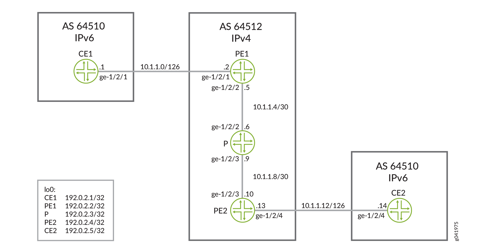
CLI Quick Configuration shows the configuration for all of the devices in Figure 1.
The section Configuring Device PE1 describes the steps on Device PE1.
Configuration
CLI Quick Configuration
To
quickly configure this example, copy the following commands, paste
them into a text file, remove any line breaks, change any details
necessary to match your network configuration, and then copy and paste
the commands into the CLI at the [edit] hierarchy level.
Device CE1
set interfaces ge-1/2/1 unit 0 family inet6 address ::10.1.1.1/126
set interfaces ge-1/2/1 unit 0 family mpls
set interfaces lo0 unit 0 family inet6 address ::192.0.2.1/32
set protocols bgp group toPE1 type internal
set protocols bgp group toPE1 family inet6 unicast
set protocols bgp group toPE1 export send-direct
set protocols bgp group toPE1 neighbor ::10.1.1.2
set policy-options policy-statement send-direct from protocol direct
set policy-options policy-statement send-direct then accept
set routing-options router-id 192.0.2.1
set routing-options autonomous-system 64510
Device CE2
set interfaces ge-1/2/4 unit 0 family inet6 address ::10.1.1.14/126
set interfaces ge-1/2/4 unit 0 family mpls
set interfaces lo0 unit 0 family inet6 address ::192.0.2.5/32
set protocols bgp group toPE2 type internal
set protocols bgp group toPE2 family inet6 unicast
set protocols bgp group toPE2 export send-direct
set protocols bgp group toPE2 neighbor ::10.1.1.13
set policy-options policy-statement send-direct from protocol direct
set policy-options policy-statement send-direct then accept
set routing-options router-id 192.0.2.5
set routing-options autonomous-system 64510
Device PE1
set interfaces ge-1/2/1 unit 0 family inet6 address ::10.1.1.2/126
set interfaces ge-1/2/2 unit 0 family inet address 10.1.1.5/30
set interfaces ge-1/2/2 unit 0 family mpls
set interfaces lo0 unit 0 family inet address 192.0.2.2/32
set protocols mpls ipv6-tunneling
set protocols mpls interface ge-1/2/2.0
set protocols bgp group toPE2 type internal
set protocols bgp group toPE2 local-address 192.0.2.2
set protocols bgp group toPE2 family inet6-vpn unicast
set protocols bgp group toPE2 neighbor 192.0.2.4
set protocols ospf area 0.0.0.0 interface lo0.0 passive
set protocols ospf area 0.0.0.0 interface ge-1/2/2.0
set protocols ldp interface ge-1/2/2.0
set protocols ldp interface lo0.0
set routing-instances red instance-type vrf
set routing-instances red interface ge-1/2/1.0
set routing-instances red route-distinguisher 64512:1
set routing-instances red vrf-target target:64512:1
set routing-instances red routing-options router-id 192.0.2.2
set routing-instances red routing-options autonomous-system 64510
set routing-instances red routing-options autonomous-system independent-domain
set routing-instances red protocols bgp group toCE1 type internal
set routing-instances red protocols bgp group toCE1 family inet6 unicast
set routing-instances red protocols bgp group toCE1 neighbor ::10.1.1.1
set routing-options router-id 192.0.2.2
set routing-options autonomous-system 64512
Device P
set interfaces ge-1/2/2 unit 0 family inet address 10.1.1.6/30
set interfaces ge-1/2/2 unit 0 family mpls
set interfaces ge-1/2/3 unit 0 family inet address 10.1.1.9/30
set interfaces ge-1/2/3 unit 0 family mpls
set interfaces lo0 unit 0 family inet address 192.0.2.3/32
set protocols mpls interface all
set protocols ospf area 0.0.0.0 interface lo0.0 passive
set protocols ospf area 0.0.0.0 interface all
set protocols ldp interface all
set routing-options router-id 192.0.2.3
Device PE2
set interfaces ge-1/2/3 unit 0 family inet address 10.1.1.10/30
set interfaces ge-1/2/3 unit 0 family mpls
set interfaces ge-1/2/4 unit 0 family inet6 address ::10.1.1.13/126
set interfaces lo0 unit 0 family inet address 192.0.2.4/32
set protocols mpls ipv6-tunneling
set protocols mpls interface ge-1/2/3.0
set protocols bgp group toPE1 type internal
set protocols bgp group toPE1 local-address 192.0.2.4
set protocols bgp group toPE1 family inet6-vpn unicast
set protocols bgp group toPE1 neighbor 192.0.2.2
set protocols ospf area 0.0.0.0 interface lo0.0 passive
set protocols ospf area 0.0.0.0 interface ge-1/2/3.0
set protocols ldp interface ge-1/2/3.0
set protocols ldp interface lo0.0
set routing-instances red instance-type vrf
set routing-instances red interface ge-1/2/4.0
set routing-instances red route-distinguisher 64512:1
set routing-instances red vrf-target target:64512:1
set routing-instances red routing-options router-id 192.0.2.4
set routing-instances red routing-options autonomous-system 64510
set routing-instances red routing-options autonomous-system independent-domain
set routing-instances red protocols bgp group toCE2 type internal
set routing-instances red protocols bgp group toCE2 family inet6 unicast
set routing-instances red protocols bgp group toCE2 neighbor ::10.1.1.14
set routing-options router-id 192.0.2.4
set routing-options autonomous-system 64512
Configuring Device PE1
Step-by-Step Procedure
The following example requires you to navigate various levels in the configuration hierarchy. For information about navigating the CLI, see Using the CLI Editor in Configuration Mode in the CLI User Guide.
To configure Device PE1:
Configure the interfaces.
[edit interfaces]
user@PE1# set ge-1/2/1 unit 0 family inet6 address ::10.1.1.2/126
user@PE1# set ge-1/2/2 unit 0 family inet address 10.1.1.5/30
user@PE1# set ge-1/2/2 unit 0 family mpls
user@PE1# set lo0 unit 0 family inet address 192.0.2.2/32
Configure MPLS on the interfaces.
[edit protocols mpls]
user@PE1# set ipv6-tunneling
user@PE1# set interface ge-1/2/2.0
Configure BGP.
[edit protocols bgp group toPE2]
user@PE1# set type internal
user@PE1# set local-address 192.0.2.2
user@PE1# set family inet6-vpn unicast
user@PE1# set neighbor 192.0.2.4
Configure an interior gateway protocol (IGP).
[edit protocols ospf area 0.0.0.0]
user@PE1# set interface lo0.0 passive
user@PE1# set interface ge-1/2/2.0
Configure a signaling protocol.
[edit protocols]
user@PE1# set ldp interface ge-1/2/2.0
user@PE1# set ldp interface lo0.0
Configure the routing instance.
[edit routing-instances red]
user@PE1# set instance-type vrf
user@PE1# set interface ge-1/2/1.0
user@PE1# set route-distinguisher 64512:1
user@PE1# set vrf-target target:64512:1
user@PE1# set routing-options router-id 192.0.2.2
user@PE1# set protocols bgp group toCE1 type internal
user@PE1# set protocols bgp group toCE1 family inet6 unicast
user@PE1# set protocols bgp group toCE1 neighbor ::10.1.1.1
In the routing instance, include the AS number of the customer network, and include the
independent-domainstatement.[edit routing-instances red routing-options] user@PE1# set autonomous-system 64510 user@PE1# set autonomous-system independent-domain
In the main instance, configure the router ID and the provider AS number.
[edit routing-options]
user@PE1# set router-id 192.0.2.2
user@PE1# set autonomous-system 64512
Results
From configuration mode, confirm your configuration
by entering the show interfaces, show protocols, show routing-instances, and show routing-options commands. If the output does not display the intended configuration,
repeat the instructions in this example to correct the configuration.
user@PE1# show interfaces
interfaces {
    ge-1/2/1 {
        unit 0 {
            family inet6 {
                address ::10.1.1.2/126;
            }
        }
    }
    ge-1/2/2 {
        unit 0 {
            family inet {
                address 10.1.1.5/30;
            }
            family mpls;
        }
    }
    lo0 {
        unit 0 {
            family inet {
                address 192.0.2.2/32;
            }
        }
    }
}
user@PE1# show protocols
mpls {
    ipv6-tunneling;
    interface ge-1/2/2.0;
}
bgp {
    group toPE2 {
        type internal;
        local-address 192.0.2.2;
        family inet6-vpn {
            unicast;
        }
        neighbor 192.0.2.4;
    }
}
ospf {
    area 0.0.0.0 {
        interface lo0.0 {
            passive;
        }
        interface ge-1/2/2.0;
    }
}
ldp {
    interface ge-1/2/2.0;
    interface lo0.0;
}
user@PE1# show routing-instances
red {
    instance-type vrf;
    interface ge-1/2/1.0;
    route-distinguisher 64512:1;
    vrf-target target:64512:1;
    routing-options {
        router-id 192.0.2.2;
        autonomous-system 64510 independent-domain;
    }
    protocols {
        bgp {
            group toCE1 {
                type internal;
                family inet6 {
                    unicast;
                }
                neighbor ::10.1.1.1;
            }
        }
    }
}
user@PE1# show routing-options
router-id 192.0.2.2;
autonomous-system 64512;
If you are done configuring the device, enter commit from configuration mode.
Verification
Confirm that the configuration is working properly.
Verifying That the CE Devices Have Connectivity
Purpose
Make sure that the tunnel is operating.
Action
From operational mode, enter the ping command.
user@CE1> ping ::192.0.2.5

PING6(56=40+8+8 bytes) ::10.1.1.1 --> ::192.0.2.5
16 bytes from ::192.0.2.5, icmp_seq=0 hlim=63 time=1.943 ms
16 bytes from ::192.0.2.5, icmp_seq=1 hlim=63 time=1.587 ms
^C
--- ::192.0.2.5 ping6 statistics ---
2 packets transmitted, 2 packets received, 0% packet loss
round-trip min/avg/max/std-dev = 1.587/1.765/1.943/0.178 ms
user@CE2> ping ::192.0.2.1
PING6(56=40+8+8 bytes) ::10.1.1.14 --> ::192.0.2.1
16 bytes from ::192.0.2.1, icmp_seq=0 hlim=63 time=2.097 ms
16 bytes from ::192.0.2.1, icmp_seq=1 hlim=63 time=1.610 ms
^C
--- ::192.0.2.1 ping6 statistics ---
2 packets transmitted, 2 packets received, 0% packet loss
round-trip min/avg/max/std-dev = 1.610/1.853/2.097/0.244 ms
Meaning
The IPv6 CE devices can communicate over the core IPv4 network.
Checking the AS Paths
Purpose
Make sure that the provider AS number does not appear in the CE device routing tables.
Action
From operational mode, enter the show route protocol
bgp detail command.
user@CE1> show route protocol bgp detail

inet6.0: 8 destinations, 8 routes (8 active, 0 holddown, 0 hidden)
::192.0.2.5/32 (1 entry, 1 announced)
        *BGP    Preference: 170/-101
                Next hop type: Indirect
                Address: 0x9514354
                Next-hop reference count: 6
                Source: ::10.1.1.2
                Next hop type: Router, Next hop index: 924
                Next hop: ::10.1.1.2 via ge-1/2/1.0, selected
                Session Id: 0x500001
                Protocol next hop: ::10.1.1.2
                Indirect next hop: 0x971c000 262147 INH Session ID: 0x500002
                State: <Active Int Ext>
                Local AS: 64510 Peer AS: 64510
                Age: 50:58      Metric2: 0
                Validation State: unverified
                Task: BGP_64510.::10.1.1.2+45824
                Announcement bits (2): 0-KRT 2-Resolve tree 2
                AS path: I
                Accepted
                Localpref: 100
                Router ID: 192.0.2.2

::10.1.1.12/126 (1 entry, 1 announced)
        *BGP    Preference: 170/-101
                Next hop type: Indirect
                Address: 0x9514354
                Next-hop reference count: 6
                Source: ::10.1.1.2
                Next hop type: Router, Next hop index: 924
                Next hop: ::10.1.1.2 via ge-1/2/1.0, selected
                Session Id: 0x500001
                Protocol next hop: ::10.1.1.2
                Indirect next hop: 0x971c000 262147 INH Session ID: 0x500002
                State: <Active Int Ext>
                Local AS: 64510 Peer AS: 64510
                Age: 50:58      Metric2: 0
                Validation State: unverified
                Task: BGP_64510.::10.1.1.2+45824
                Announcement bits (2): 0-KRT 2-Resolve tree 2
                AS path: I
                Accepted
                Localpref: 100
Router ID: 192.0.2.2user@CE2> show route protocol bgp detail
inet6.0: 8 destinations, 8 routes (8 active, 0 holddown, 0 hidden)
::192.0.2.1/32 (1 entry, 1 announced)
*BGP Preference: 170/-101
Next hop type: Indirect
Address: 0x9514354
Next-hop reference count: 6
Source: ::10.1.1.13
Next hop type: Router, Next hop index: 914
Next hop: ::10.1.1.13 via ge-1/2/4.0, selected
Session Id: 0x400001
Protocol next hop: ::10.1.1.13
Indirect next hop: 0x971c000 262150 INH Session ID: 0x400002
State: <Active Int Ext>
Local AS: 64510 Peer AS: 64510
Age: 50:41 Metric2: 0
Validation State: unverified
Task: BGP_64510.::10.1.1.13+59329
Announcement bits (2): 0-KRT 2-Resolve tree 2
AS path: I
Accepted
Localpref: 100
Router ID: 192.0.2.4
::10.1.1.0/126 (1 entry, 1 announced)
*BGP Preference: 170/-101
Next hop type: Indirect
Address: 0x9514354
Next-hop reference count: 6
Source: ::10.1.1.13
Next hop type: Router, Next hop index: 914
Next hop: ::10.1.1.13 via ge-1/2/4.0, selected
Session Id: 0x400001
Protocol next hop: ::10.1.1.13
Indirect next hop: 0x971c000 262150 INH Session ID: 0x400002
State: <Active Int Ext>
Local AS: 64510 Peer AS: 64510
Age: 50:41 Metric2: 0
Validation State: unverified
Task: BGP_64510.::10.1.1.13+59329
Announcement bits (2): 0-KRT 2-Resolve tree 2
AS path: I
Accepted
Localpref: 100
Router ID: 192.0.2.4
Meaning
The output shows that for the BGP routes on the CE devices, the AS path attribute does not include the provider AS 64512.