ON THIS PAGE
Example: Interconnecting a Layer 2 VPN with a Layer 2 VPN
This example provides a step-by-step procedure for interconnecting and verifying a Layer 2 VPN with a Layer 2 VPN. It contains the following sections:
Requirements
This example uses the following hardware and software components:
Junos OS Release 9.3 or later
2 MX Series 5G Universal Routing Platforms
2 M Series Multiservice Edge Routers
1 T Series Core Routers
1 EX Series Ethernet Switches
Overview and Topology
Topology
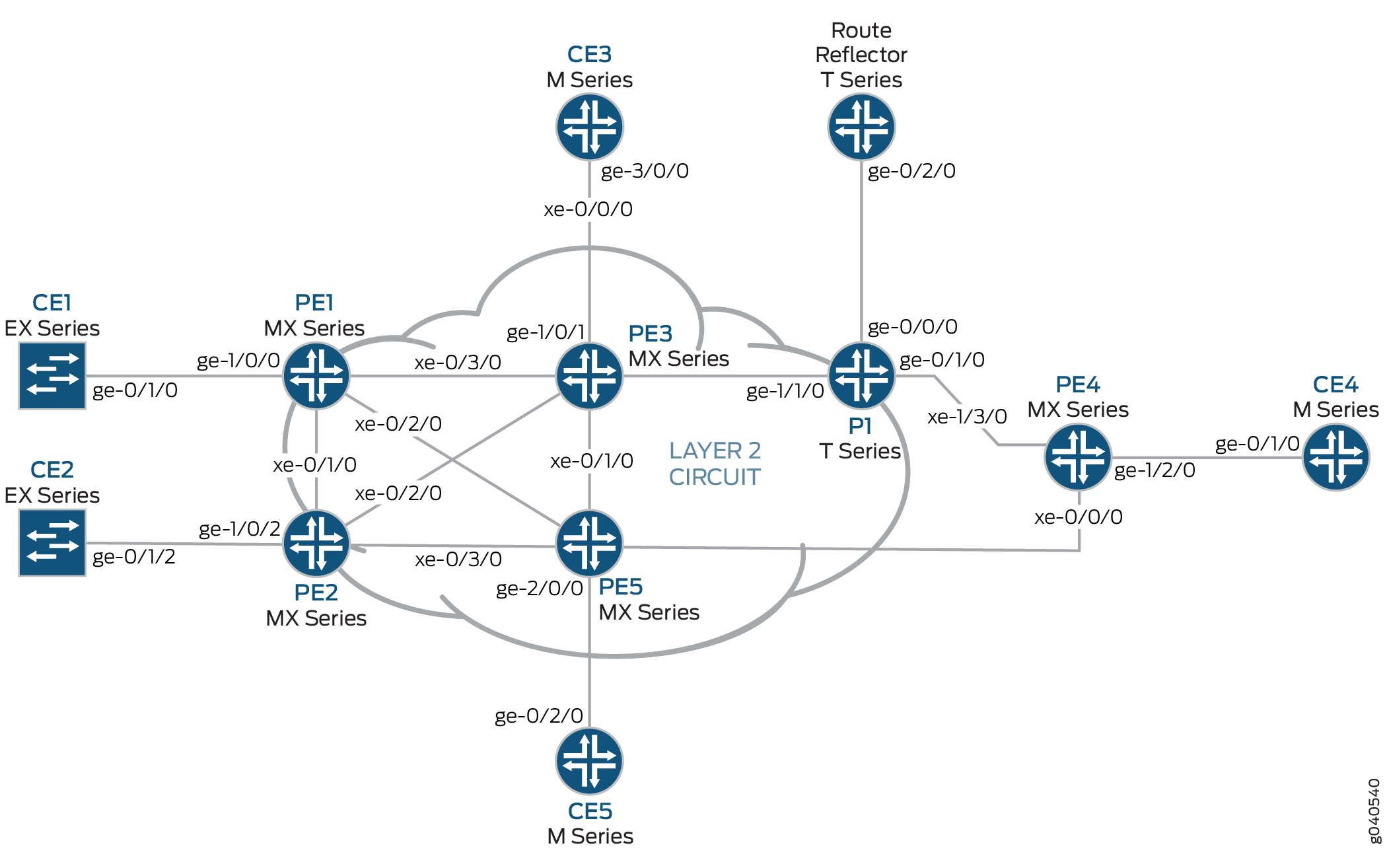
The physical topology of the Layer 2 VPN to Layer 2 VPN connection example is shown in Figure 1.
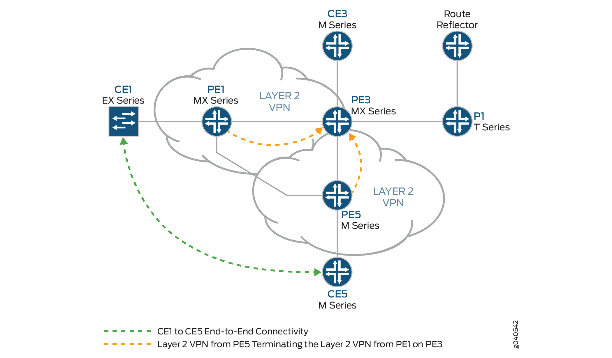
The logical topology of a Layer 2 VPN to Layer 2 VPN connection is shown in Figure 2.
Configuration
In any configuration session, it is good practice to verify
periodically that the configuration can be committed using the commit check command.
In this example, the router being configured is identified using the following command prompts:
CE1identifies the customer edge 1 (CE1) routerPE1identifies the provider edge 1 (PE1) routerCE3identifies the customer edge 3 (CE3) routerPE3identifies the provider edge 3 (PE3) routerCE5identifies the customer edge 5 (CE5) routerPE5identifies the provider edge 5 (PE5) router
This example is organized in the following sections:
- Configuring Protocols on the PE and P Routers
- Verifying the Layer 2 VPN to Layer 2 VPN Connection on Router PE3
- Verifying the Layer 2 VPN to Layer 2 VPN Connection on Router PE3
- Results
Configuring Protocols on the PE and P Routers
Step-by-Step Procedure
All of the PE routers and P routers are configured with
OSPF as the IGP protocol. The MPLS, LDP, and BGP protocols are enabled
on all of the interfaces except fxp.0. Core-facing interfaces
are enabled with the MPLS address and inet address.
Configure all the PE and P routers with OSPF as the IGP. Enable the MPLS, LDP, and BGP protocols on all interfaces except
fxp.0. The following configuration snippet shows the protocol configuration for Router PE1:[edit] protocols { mpls { interface all; interface fxp0.0 { disable; } } bgp { group RR { type internal; local-address 192.0.2.1; family l2vpn { signaling; } neighbor 192.0.2.7; } } ospf { traffic-engineering; area 0.0.0.0 { interface all; interface fxp0.0 { disable; } } } ldp { interface all; interface fxp0.0 { disable; } } }Configure the PE and P routers with OSPF as the IGP. Enable the MPLS, LDP, and BGP protocols on all interfaces except
fxp.0. The following configuration snippet shows the protocol configuration for Router PE3:[edit] protocols { mpls { interface all; interface fxp0.0 { disable; } } bgp { group RR { type internal; local-address 192.0.2.3; family l2vpn { signaling; } neighbor 192.0.2.7; } } ospf { traffic-engineering; area 0.0.0.0 { interface all; interface fxp0.0 { disable; } } } ldp { interface all; interface fxp0.0 { disable; } } }
Step-by-Step Procedure
Configuring the Layer 2 VPN Protocol and Interfaces
On Router PE1, configure the
ge-1/0/0interface encapsulation. To configure the interface encapsulation, include theencapsulationstatement and specify theethernet-cccoption (vlan-ccc encapsulation is also supported). Configure thege-1/0/0.0logical interface family for circuit cross-connect functionality. To configure the logical interface family, include thefamilystatement and specify thecccoption. The encapsulation should be configured the same way for all routers in the Layer 2 VPN domain.[edit interfaces] ge-1/0/0 { encapsulation ethernet-ccc; unit 0 { family ccc; } } lo0 { unit 0 { family inet { address 192.0.2.1/24; } } }On Router PE1, configure the Layer 2 VPN protocols. Configure the remote site ID as 3. Site ID 3 represents Router PE3 (Hub-PE). To configure the Layer 2 VPN protocols, include the
l2vpnstatement at the[edit routing-instances routing-instances-name protocols]hierarchy level. Layer 2 VPNs use BGP as the signaling protocol.[edit routing-instances] L2VPN { instance-type l2vpn; interface ge-1/0/0.0; route-distinguisher 65000:1; vrf-target target:65000:2; protocols { l2vpn { encapsulation-type ethernet; site CE1 { site-identifier 1; interface ge-1/0/0.0 { remote-site-id 3; } } } } }On Router PE5, configure the
ge-2/0/0interface encapsulation by including theencapsulationstatement and specify theethernet-cccoption. Configure the ge-1/0/0.0 logical interface family for circuit cross-connect functionality by including thefamilystatement and specifying thecccoption.[edit interfaces] ge-2/0/0 { encapsulation ethernet-ccc; unit 0 { family ccc; } } lo0 { unit 0 { family inet { address 192.0.2.5/24; } } }On Router PE5, configure the Layer 2 VPN protocols by including the
l2vpnstatement at the[edit routing-instances routing-instances-name protocols]hierarchy level. Configure the remote site ID as3.[edit routing-instances] L2VPN { instance-type l2vpn; interface ge-2/0/0.0; route-distinguisher 65000:5; vrf-target target:65000:2; protocols { l2vpn { encapsulation-type ethernet; site CE5 { site-identifier 5; interface ge-2/0/0.0 { remote-site-id 3; } } } } }On Router PE3, configure the
iw0interface with two logical interfaces. To configure theiw0interface, include theinterfacesstatement and specifyiw0as the interface name. For the unit 0 logical interface, include thepeer-unitstatement and specify the logical interfaceunit 1as the peer interface. For the unit 1 logical interface, include thepeer-unitstatement and specify the logical interfaceunit 0as the peer interface.[edit interfaces] iw0 { unit 0 { encapsulation ethernet-ccc; peer-unit 1; } unit 1 { encapsulation ethernet-ccc; peer-unit 0; } }On Router PE3, configure the edge-facing
ge-1/0/1interface encapsulation by including theencapsulationstatement and specifying theethernet-cccoption.[edit interfaces] ge-1/0/1 { encapsulation ethernet-ccc; unit 0 { family ccc; } }On Router PE3, configure the logical loopback interface. The loopback interface is used to establish the targeted LDP sessions to Routers PE1 and Router PE5.
[edit interfaces]
lo0 {
    unit 0 {
        family inet {
            address 192.0.2.3/24;
        }
    }
}
On Router PE3, enable the Layer 2 interworking protocol. To enable the Layer 2 interworking protocol, include the
l2iwstatement at the[edit protocols]hierarchy level.[edit protocols] l2iw;
On Router PE3, configure two Layer 2 VPN routing instances to terminate the Layer 2 VPN virtual circuits from Router PE1 and Router PE5, as shown.
[edit routing-instances]
L2VPN-PE1 {
    instance-type l2vpn;
    interface iw0.0;
    route-distinguisher 65000:3;
    vrf-target target:65000:2;
    protocols {
        l2vpn {
            encapsulation-type ethernet;
            site CE3 {
                site-identifier 3;
                interface iw0.0 {
                    remote-site-id 1;
                }
            }
        }
    }
}
L2VPN-PE5 {
    instance-type l2vpn;
    interface iw0.1;
    route-distinguisher 65000:33;
    vrf-target target:65000:2;
    protocols {
        l2vpn {
            encapsulation-type ethernet;
            site CE3 {
                site-identifier 3;
                interface iw0.1 {
                    remote-site-id 5;
                }
            }
        }
    }
}
Verifying the Layer 2 VPN to Layer 2 VPN Connection on Router PE3
Step-by-Step Procedure
BGP is used for control plane signaling in a Layer 2 VPN. On Router PE1, use the
show bgpcommand to verify that the BGP control plane for the Layer 2 VPN, has established a neighbor relationship with the route reflector that has IP address192.0.2.7.Three Layer 2 VPN routes are received from the route reflector for each PE router in the topology.
user@PE1> show bgp summary
Groups: 1 Peers: 1 Down peers: 0
Table          Tot Paths  Act Paths Suppressed    History Damp State    Pending
bgp.l2vpn.0            3          3          0          0          0          0
Peer                     AS      InPkt     OutPkt    OutQ   Flaps Last Up/Dwn State|#Active/Received/Accepted/Damped...
192.0.2.7               65000        190        192       0       0     1:24:40 Establ
  bgp.l2vpn.0: 3/3/3/0
  L2VPN.l2vpn.0: 3/3/3/0
On Router PE1, use the
show routecommand to verify that the BGP Layer 2 VPN routes are stored in theL2VPN.l2vpn.0routing table for each PE router.user@PE1> show route table L2VPN.l2vpn.0 L2VPN.l2vpn.0: 4 destinations, 4 routes (4 active, 0 holddown, 0 hidden) + = Active Route, - = Last Active, * = Both 65000:1:1:3/96 *[L2VPN/170/-101] 01:31:53, metric2 1 Indirect 65000:3:3:1/96 *[BGP/170] 01:24:58, localpref 100, from 192.0.2.7 AS path: I > to 10.10.1.2 via xe-0/3/0.0 65000:5:5:3/96 *[BGP/170] 01:24:58, localpref 100, from 192.0.2.7 AS path: I > to 10.10.3.2 via xe-0/2/0.0 65000:33:3:5/96 *[BGP/170] 01:24:58, localpref 100, from 192.0.2.7 AS path: I > to 10.10.1.2 via xe-0/3/0.0On Router PE1, use the
show ldp sessioncommand to verify that targeted LDP sessions are established to the PE routers in the network and that the state isOperational.user@PE1> show ldp session Address State Connection Hold time 192.0.2.2 Operational Open 24 192.0.2.3 Operational Open 22 192.0.2.5 Operational Open 28
On Router PE1, use the
show l2vpn connectionscommand to verify that the Layer 2 VPN to site 3 on Router PE3 (Hub-PE) isUp.user@PE1> show l2vpn connections Layer-2 VPN connections: Legend for connection status (St) EI -- encapsulation invalid NC -- interface encapsulation not CCC/TCC/VPLS EM -- encapsulation mismatch WE -- interface and instance encaps not same VC-Dn -- Virtual circuit down NP -- interface hardware not present CM -- control-word mismatch -> -- only outbound connection is up CN -- circuit not provisioned <- -- only inbound connection is up OR -- out of range Up -- operational OL -- no outgoing label Dn -- down LD -- local site signaled down CF -- call admission control failure RD -- remote site signaled down SC -- local and remote site ID collision LN -- local site not designated LM -- local site ID not minimum designated RN -- remote site not designated RM -- remote site ID not minimum designated XX -- unknown connection status IL -- no incoming label MM -- MTU mismatch MI -- Mesh-Group ID not availble BK -- Backup connection ST -- Standby connection PF -- Profile parse failure PB -- Profile busy Legend for interface status Up -- operational Dn -- down Instance: L2VPN Local site: CE1 (1) connection-site Type St Time last up # Up trans 3 rmt Up Jan 5 18:08:25 2010 1 Remote PE: 192.0.2.3, Negotiated control-word: Yes (Null) Incoming label: 800000, Outgoing label: 800000 Local interface: ge-1/0/0.0, Status: Up, Encapsulation: ETHERNET 5 rmt OROn Router PE1, use the
show routecommand to verify that thempls.0routing table is populated with the Layer 2 VPN routes used to forward the traffic using an LDP label. Notice that in this example, the router is pushing label8000000.user@PE1> show route table mpls.0 [edit] mpls.0: 13 destinations, 13 routes (13 active, 0 holddown, 0 hidden) + = Active Route, - = Last Active, * = Both 0 *[MPLS/0] 1w1d 11:36:44, metric 1 Receive 1 *[MPLS/0] 1w1d 11:36:44, metric 1 Receive 2 *[MPLS/0] 1w1d 11:36:44, metric 1 Receive 300432 *[LDP/9] 3d 04:25:02, metric 1 > to 10.10.2.2 via xe-0/1/0.0, Pop 300432(S=0) *[LDP/9] 3d 04:25:02, metric 1 > to 10.10.2.2 via xe-0/1/0.0, Pop 300768 *[LDP/9] 3d 04:25:02, metric 1 > to 10.10.3.2 via xe-0/2/0.0, Pop 300768(S=0) *[LDP/9] 3d 04:25:02, metric 1 > to 10.10.3.2 via xe-0/2/0.0, Pop 300912 *[LDP/9] 3d 04:25:02, metric 1 > to 10.10.3.2 via xe-0/2/0.0, Swap 299856 301264 *[LDP/9] 3d 04:24:58, metric 1 > to 10.10.1.2 via xe-0/3/0.0, Swap 308224 301312 *[LDP/9] 3d 04:25:01, metric 1 > to 10.10.1.2 via xe-0/3/0.0, Pop 301312(S=0) *[LDP/9] 3d 04:25:01, metric 1 > to 10.10.1.2 via xe-0/3/0.0, Pop 800000 *[L2VPN/7] 01:25:28 > via ge-1/0/0.0, Pop Offset: 4 ge-1/0/0.0 *[L2VPN/7] 01:25:28, metric2 1 > to 10.10.1.2 via xe-0/3/0.0, Push 800000 Offset: -4
Verifying the Layer 2 VPN to Layer 2 VPN Connection on Router PE3
Step-by-Step Procedure
On Router PE3, use the
show l2vpn connectionscommand to verify that the Layer 2 VPN connections from Router PE1 and Router PE5 areUpand are using theiw0interface.user@PE3> show l2vpn connections Instance: L2VPN-PE1 Local site: CE3 (3) connection-site Type St Time last up # Up trans 1 rmt Up Jan 5 18:08:22 2010 1 Remote PE: 192.0.2.1, Negotiated control-word: Yes (Null) Incoming label: 800000, Outgoing label: 800000 Local interface: iw0.0, Status: Up, Encapsulation: ETHERNET 5 rmt OR Instance: L2VPN-PE5 Local site: CE3 (3) connection-site Type St Time last up # Up trans 1 rmt CN 5 rmt Up Jan 5 18:08:22 2010 1 Remote PE: 192.0.2.5, Negotiated control-word: Yes (Null) Incoming label: 800002, Outgoing label: 800000 Local interface: iw0.1, Status: Up, Encapsulation: ETHERNETOn Router PE3, use the
show ldp neighborcommand to verify that the targeted LDP session neighbor IP addresses are shown.user@PE3> show ldp neighbor Address Interface Label space ID Hold time 192.0.2.1 lo0.0 192.0.2.1:0 44 192.0.2.2 lo0.0 192.0.2.2:0 42 192.0.2.4 lo0.0 192.0.2.4:0 31 192.0.2.5 lo0.0 192.0.2.5:0 44
On Router PE3, use the
show bgp summarycommand to verify that the BGP control plane for the Layer 2 VPN, has established a neighbor relationship with the route reflector that has IP address192.0.2.7.user@PE3> show bgp summary Groups: 1 Peers: 1 Down peers: 0 Table Tot Paths Act Paths Suppressed History Damp State Pending bgp.l2vpn.0 2 2 0 0 0 0 Peer AS InPkt OutPkt OutQ Flaps Last Up/Dwn State|#Active/Received/Accepted/Damped... 192.0.2.7 65000 10092 10195 0 0 3d 4:23:27 Establ bgp.l2vpn.0: 2/2/2/0 L2VPN-PE1.l2vpn.0: 2/2/2/0 L2VPN-PE5.l2vpn.0: 2/2/2/0
On Router PE3, use the
show ldp sessioncommand to verify that targeted LDP sessions are established to all of the PE routers in the network and that the state isOperational.user@PE3> show ldp session Address State Connection Hold time 192.0.2.1
OperationalOpen 24 192.0.2.2OperationalOpen 22 192.0.2.4OperationalOpen 20 192.0.2.5OperationalOpen 24On Router PE3, use the
show routecommand to verify that thempls.0routing table is populated with the Layer 2 VPN routes used to forward the traffic using an LDP label. Notice that in this example, the router is swapping label800000. Also notice the twoiw0interfaces that are used for the Layer 2 interworking routes.user@PE3>show route table mpls.0 mpls.0: 16 destinations, 18 routes (16 active, 2 holddown, 0 hidden) + = Active Route, - = Last Active, * = Both 0 *[MPLS/0] 1w1d 11:50:14, metric 1 Receive 1 *[MPLS/0] 1w1d 11:50:14, metric 1 Receive 2 *[MPLS/0] 1w1d 11:50:14, metric 1 Receive 308160 *[LDP/9] 3d 04:38:45, metric 1 > to 10.10.1.1 via xe-0/3/0.0, Pop 308160(S=0) *[LDP/9] 3d 04:38:45, metric 1 > to 10.10.1.1 via xe-0/3/0.0, Pop 308176 *[LDP/9] 3d 04:38:44, metric 1 > to 10.10.6.2 via xe-0/1/0.0, Pop 308176(S=0) *[LDP/9] 3d 04:38:44, metric 1 > to 10.10.6.2 via xe-0/1/0.0, Pop 308192 *[LDP/9] 00:07:18, metric 1 > to 10.10.20.1 via xe-0/0/0.0, Swap 601649 to 10.10.6.2 via xe-0/1/0.0, Swap 299856 308208 *[LDP/9] 3d 04:38:44, metric 1 > to 10.10.5.1 via xe-0/2/0.0, Pop 308208(S=0) *[LDP/9] 3d 04:38:44, metric 1 > to 10.10.5.1 via xe-0/2/0.0, Pop 308224 *[LDP/9] 3d 04:38:42, metric 1 > to 10.10.20.1 via xe-0/0/0.0, Pop 308224(S=0) *[LDP/9] 3d 04:38:42, metric 1 > to 10.10.20.1 via xe-0/0/0.0, Pop 800000 *[L2IW/6] 01:39:13, metric2 1 > to 10.10.6.2 via xe-0/1/0.0, Swap 800000 [L2VPN/7] 01:39:13 > via iw0.0, Pop Offset: 4 800002 *[L2IW/6] 01:39:13, metric2 1 > to 10.10.1.1 via xe-0/3/0.0, Swap 800000 [L2VPN/7] 01:39:13 > via iw0.1, Pop Offset: 4 iw0.0 *[L2VPN/7] 01:39:13, metric2 1 > to 10.10.1.1 via xe-0/3/0.0, Push 800000 Offset: -4 iw0.1 *[L2VPN/7] 01:39:13, metric2 1 > to 10.10.6.2 via xe-0/1/0.0, Push 800000 Offset: -4
Step-by-Step Procedure
Testing Layer 2 VPN to Layer 2 VPN Connectivity (CE1 to CE5)
On Router CE1, use the
pingcommand to test connectivity to Router CE5. Notice that the response time is in milliseconds, confirming that the ping response is returned.user@CE1>ping 198.51.100.11 PING 198.51.100.11 (198.51.100.11): 56 data bytes 64 bytes from 198.51.100.11: icmp_seq=1 ttl=64 time=22.425 ms 64 bytes from 198.51.100.11: icmp_seq=2 ttl=64 time=1.299 ms 64 bytes from 198.51.100.11: icmp_seq=3 ttl=64 time=1.032 ms 64 bytes from 198.51.100.11: icmp_seq=4 ttl=64 time=1.029 ms
On Router CE5, use the
pingcommand to test connectivity to Router CE1. Notice that the response time is in milliseconds, confirming that the ping response is returned.user@CE5>ping 198.51.100.1 PING 198.51.100.1 (198.51.100.1): 56 data bytes 64 bytes from 198.51.100.1: icmp_seq=0 ttl=64 time=1.077 ms 64 bytes from 198.51.100.1: icmp_seq=1 ttl=64 time=0.957 ms 64 bytes from 198.51.100.1: icmp_seq=2 ttl=64 time=1.057 ms 1.017 ms
Results
The configuration and verification of this example have been completed. The following section is for your reference.
The relevant sample configuration for Router PE1 follows.
Router PE1
chassis {
    dump-on-panic;
    fpc 1 {
        pic 3 {
            tunnel-services {
                bandwidth 1g;
            }
        }
    }
    network-services ethernet;
}
    interfaces {
        xe-0/1/0 {
            unit 0 {
                family inet {
                    address 10.10.2.1/30;
                }
                family mpls;
            }
        }
        xe-0/2/0 {
            unit 0 {
                family inet {
                    address 10.10.3.1/30;
                }
                family mpls;
            }
        }
        xe-0/3/0 {
            unit 0 {
                family inet {
                    address 10.10.1.1/30;
                }
                family mpls;
            }
        }
        ge-1/0/0 {
            encapsulation ethernet-ccc;
            unit 0 {
                family ccc;
            }
        }
        lo0 {
            unit 0 {
                family inet {
                    address 192.0.2.1/24;
                }
            }
        }
    }
    routing-options {
        static {
            route 172.16.0.0/8 next-hop 172.19.59.1;
        }
        autonomous-system 65000;
    }
    protocols {
        mpls {
            interface all;
            interface fxp0.0 {
                disable;
            }
        }
        bgp {
            group RR {
                type internal;
                local-address 192.0.2.1;
                family l2vpn {
                    signaling;
                }
                neighbor 192.0.2.7;
            }
        }
        ospf {
            traffic-engineering;
            area 0.0.0.0 {
                interface all;
                interface fxp0.0 {
                    disable;
                }
            }
        }
        ldp {
            interface all;
            interface fxp0.0 {
                disable;
            }
        }
    }
    routing-instances {
        L2VPN {
            instance-type l2vpn;
            interface ge-1/0/0.0;
            route-distinguisher 65000:1;
            vrf-target target:65000:2;
            protocols {
                l2vpn {
                    encapsulation-type ethernet;
                    site CE1 {
                        site-identifier 1;
                        interface ge-1/0/0.0 {
                            remote-site-id 3;
                        }
                    }
                }
            }
        }
    }
The relevant sample configuration for Router PE3 follows.
Router PE3
chassis {
    dump-on-panic;
    fpc 1 {
        pic 3 {
            tunnel-services {
                bandwidth 1g;
            }
        }
    }
    network-services ethernet;
}
interfaces {
    xe-0/0/0 {
        unit 0 {
            family inet {
                address 10.10.20.2/30;
            }
            family mpls;
        }
    }
    xe-0/1/0 {
        unit 0 {
            family inet {
                address 10.10.6.1/30;
            }
            family mpls;
        }
    }
    xe-0/2/0 {
        unit 0 {
            family inet {
                address 10.10.5.2/30;
            }
            family mpls;
        }
    }
    xe-0/3/0 {
        unit 0 {
            family inet {
                address 10.10.1.2/30;
            }
            family mpls;
        }
    }
    ge-1/0/1 {
        encapsulation ethernet-ccc;
        unit 0 {
            family ccc;
        }
    }
    iw0 {
        unit 0 {
            encapsulation ethernet-ccc;
            peer-unit 1;
        }
        unit 1 {
            encapsulation ethernet-ccc;
            peer-unit 0;
        }
    }
    lo0 {
        unit 0 {
            family inet {
                address 192.0.2.3/24;
            }
        }
    }
}
routing-options {
    static {
        route 172.16.0.0/8 next-hop 172.19.59.1;
    }
    autonomous-system 65000;
}
protocols {
    l2iw;
    mpls {
        interface all;
        interface fxp0.0 {
            disable;
        }
    }
    bgp {
        group RR {
            type internal;
            local-address 192.0.2.3;
            family l2vpn {
                signaling;
            }
            neighbor 192.0.2.7;
        }
    }
    ospf {
        area 0.0.0.0 {
            interface all;
            interface fxp0.0 {
                disable;
            }
        }
    }
    ldp {
        interface all;
        interface fxp0.0 {
            disable;
        }
    }
}
routing-instances {
    L2VPN-PE1 {
        instance-type l2vpn;
        interface iw0.0;
        route-distinguisher 65000:3;
        vrf-target target:65000:2;
        protocols {
            l2vpn {
                encapsulation-type ethernet;
                site CE3 {
                    site-identifier 3;
                    interface iw0.0 {
                        remote-site-id 1;
                    }
                }
            }
        }
    }
    L2VPN-PE5 {
        instance-type l2vpn;
        interface iw0.1;
        route-distinguisher 65000:33;
        vrf-target target:65000:2;
        protocols {
            l2vpn {
                encapsulation-type ethernet;
                site CE3 {
                    site-identifier 3;
                    interface iw0.1 {
                        remote-site-id 5;
                    }
                }
            }
        }
    }
}