ON THIS PAGE
Example: Interconnecting a Layer 2 Circuit with a Layer 2 VPN
This example provides a step-by-step procedure and commands for configuring and verifying a Layer 2 circuit to a Layer 2 VPN. It contains the following sections:
Requirements
This example uses the following hardware and software components:
Junos OS Release 9.3 or later
2 MX Series 5G Universal Routing Platforms
2 M Series Multiservice Edge Router
1 T Series Core Router
1 EX Series Ethernet Switch
Overview and Topology
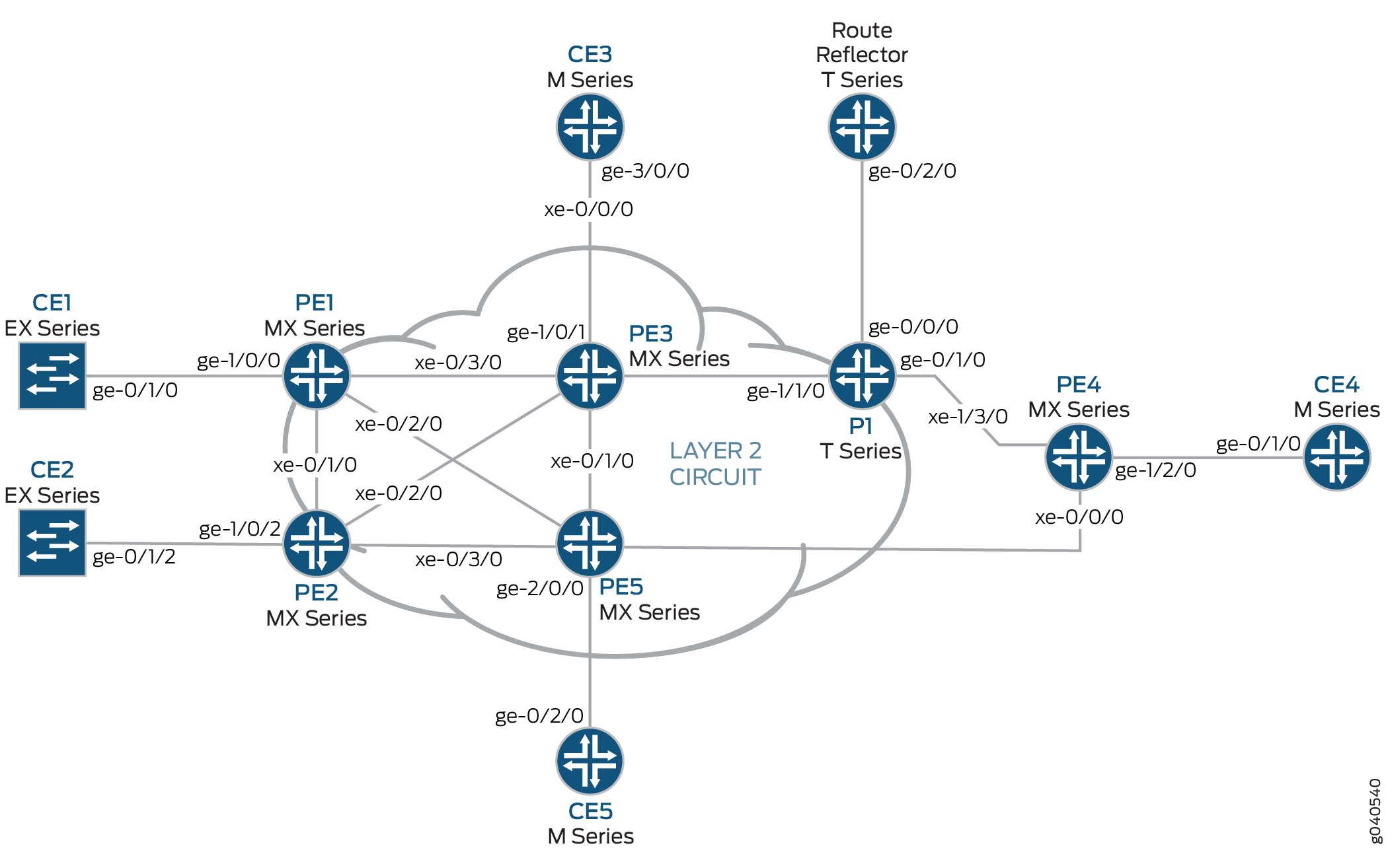
Topology
The physical topology of a Layer 2 circuit to a Layer 2 VPN connection is shown in Figure 1.
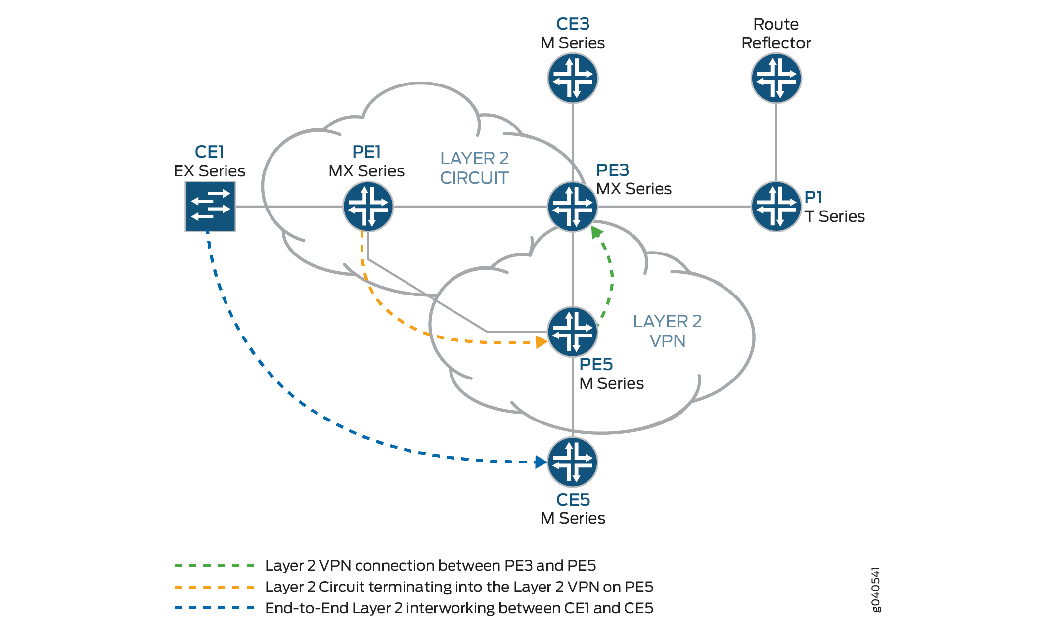
The logical topology of a Layer 2 circuit to a Layer 2 VPN connection is shown in Figure 2.
Configuration
In any configuration session, it is good practice to verify
periodically that the configuration can be committed using the commit check command.
In this example, the router being configured is identified using the following command prompts:
CE1identifies the customer edge 1 (CE1) routerPE1identifies the provider edge 1 (PE1) routerCE3identifies the customer edge 3 (CE3) routerPE3identifies the provider edge 3 (PE3) routerCE5identifies the customer edge 5 (CE5) routerPE5identifies the provider edge 5 (PE5) router
This example is organized in the following sections:
Configuring Protocols on the PE and P Routers
Step-by-Step Procedure
In this example, all of the PE routers and P routers are configured with OSPF as the IGP protocol. The MPLS, LDP, and BGP protocols are enabled on all of the interfaces except fxp.0. Core-facing interfaces are enabled with the MPLS address and inet address.
Configure all the PE and P routers with OSPF as the IGP. Enable the MPLS, LDP, and BGP protocols on all interfaces except
fxp.0. LDP is used as the signaling protocol on Router PE1 for the Layer 2 circuit. The following configuration snippet shows the protocol configuration for Router PE1:[edit] protocols { mpls { interface all; interface fxp0.0 { disable; } } bgp { group RR { type internal; local-address 192.0.2.1; family l2vpn { signaling; } neighbor 192.0.2.7; } } ospf { traffic-engineering; area 0.0.0.0 { interface all; interface fxp0.0 { disable; } } } ldp { interface all; interface fxp0.0 { disable; } } }Configure the PE and P routers with OSPF as the IGP. Enable the MPLS, LDP, and BGP protocols on all interfaces except
fxp.0. BGP is used as the signaling protocol on Router PE3 for the Layer 2 VPN. The following configuration snippet shows the protocol configuration for Router PE3:[edit] protocols { mpls { interface all; interface fxp0.0 { disable; } } bgp { group RR { type internal; local-address 192.0.2.3; family l2vpn { signaling; } neighbor 192.0.2.7; } } ospf { traffic-engineering; area 0.0.0.0 { interface all; interface fxp0.0 { disable; } } } ldp { interface all; interface fxp0.0 { disable; } } }
Step-by-Step Procedure
Configuring Interfaces
On Router PE1, configure the
ge-1/0/0interface encapsulation. To configure the interface encapsulation, include theencapsulationstatement and specify theethernet-cccoption (vlan-ccc encapsulation is also supported). Configure thege-1/0/0.0logical interface family for circuit cross-connect functionality. To configure the logical interface family, include thefamilystatement and specify thecccoption. The encapsulation should be configured the same way for all routers in the Layer 2 circuit domain.[edit interfaces] ge-1/0/0 { encapsulation ethernet-ccc; unit 0 { family ccc; } } lo0 { unit 0 { family inet { address 192.0.2.1/24; } } }Router PE5 is the router that is stitching the Layer 2 circuit to the Layer 2 VPN using the interworking interface. The configuration of the peer unit interfaces is what makes the interconnection.
On Router PE5, configure the
iw0interface with two logical interfaces. To configure theiw0interface, include theinterfacesstatement and specifyiw0as the interface name. For the unit 0 logical interface, include thepeer-unitstatement and specify the logical interfaceunit 1as the peer interface. For the unit 1 logical interface, include thepeer-unitstatement and specify the logical interfaceunit 0as the peer interface.[edit interfaces] iw0 { unit 0 { encapsulation ethernet-ccc; peer-unit 1; } unit 1 { encapsulation ethernet-ccc; peer-unit 0; } }On Router PE5, configure the logical loopback interface. The loopback interface is used to establish the targeted LDP sessions to Routers PE1 and PE5.
[edit interfaces]
lo0 {
    unit 0 {
        family inet {
            address 192.0.2.5/24;
        }
    }
}
Step-by-Step Procedure
Configuring the Layer 2 circuit protocol
On Router PE1, configure the IP address of the remote PE router with the
neighborstatement. The loopback address and router ID of the PE neighbor is commonly the neighbor’s IP address. To allow a Layer 2 circuit to be established even though the maximum transmission unit (MTU) configured on the PE router does not match the MTU configured on the remote PE router, include theignore-mtu-mismatchstatement.[edit] protocols { l2circuit { neighbor 192.0.2.5 { interface ge-1/0/0.0 { virtual-circuit-id 100; no-control-word; ignore-mtu-mismatch; } } } }On Router PE5, configure the IP address of the remote PE router. To configure the IP address of the remote PE router, include the
neighborstatement and specify the IP address of the loopback interface on Router PE1. Configure the virtual circuit ID to be the same as the virtual circuit ID on the neighbor router. To allow a Layer 2 circuit to be established even though the MTU configured on the local PE router does not match the MTU configured on the remote PE router, include theignore-mtu-mismatchstatement. Also disable the use of the control word for demultiplexing by including theno-control-wordstatement.[edit protocols] l2circuit { neighbor 192.0.2.1 { interface iw0.0 { virtual-circuit-id 100; no-control-word; ignore-mtu-mismatch; } } }On Router PE5, configure the Layer 2 VPN protocols by including the
l2vpnstatement at the[edit routing-instances routing-instances-name protocols]hierarchy level. To configure theiw0interface, include theinterfacesstatement and specifyiw0as the interface name. Theiw0interface is configured under the Layer 2 VPN protocols to receive the looped packet from theiw0.1logical interface. Thel2vpnprotocol is configured on Router PE5 with site CE5, which is configured in the BGP L2VPN routing instance. Router CE1 has communication to Router CE5, through the Layer 2 interworking configuration on Router PE5.[edit] routing-instances { L2VPN { instance-type l2vpn; interface ge-2/0/0.0; interface iw0.1; route-distinguisher 65000:5; vrf-target target:65000:2; protocols { l2vpn { no-control-word; encapsulation-type ethernet; site CE5 { site-identifier 5; interface ge-2/0/0.0 { remote-site-id 3; } } site l2-circuit { site-identifier 6; interface iw0.1 { remote-site-id 3; } } } } } }In addition to the
iw0interface configuration, the Layer 2 interworkingl2iwprotocol must be configured. Without thel2iwprotocol configuration, the Layer 2 interworking routes are not formed, regardless of whether anyiwinterfaces are present.On Router PE5, configure the
l2iwprotocol. To configure the protocol, include thel2iwstatement at the[edit protocols]hierarchy level.[edit] protocols { l2iw; }
Verification
Step-by-Step Procedure
Verifying the Layer 2 Circuit Connection on Router PE1.
On Router PE1, use the
show l2circuit connectionscommand to verify that the Layer 2 Circuit from Router PE1 to Router PE5 isUp.user@PE1> show l2circuit connections Layer-2 Circuit Connections: Legend for connection status (St) EI -- encapsulation invalid NP -- interface h/w not present MM -- mtu mismatch Dn -- down EM -- encapsulation mismatch VC-Dn -- Virtual circuit Down CM -- control-word mismatch Up -- operational VM -- vlan id mismatch CF -- Call admission control failure OL -- no outgoing label IB -- TDM incompatible bitrate NC -- intf encaps not CCC/TCC TM -- TDM misconfiguration BK -- Backup Connection ST -- Standby Connection CB -- rcvd cell-bundle size bad XX -- unknown SP -- Static Pseudowire Legend for interface status Up -- operational Dn -- down Neighbor: 192.0.2.5 Interface Type St Time last up # Up trans ge-1/0/0.0(vc 100) rmtUpJan 3 22:00:49 2010 1 Remote PE: 192.0.2.5, Negotiated control-word: No Incoming label: 301328, Outgoing label: 300192 Local interface: ge-1/0/0.0, Status: Up, Encapsulation: ETHERNETOn Router PE5, use the
show l2vpn connectionscommand to verify that the Layer 2 VPN connection isUpusing theiw0peer interface of the Layer 2 circuit.user@PE5> show l2vpn connections Instance: L2VPN Local site: CE5 (5) connection-site Type St Time last up # Up trans l2-circuit (6) loc OR 3 rmtUpJan 3 22:51:12 2010 1 Remote PE: 192.0.2.3, Negotiated control-word: No Incoming label: 800258, Outgoing label: 800000 Local interface: ge-2/0/0.0, Status: Up, Encapsulation: ETHERNET Local site: l2-circuit (6) connection-site Type St Time last up # Up trans CE5 (5) loc OR 3 rmt Up Jan 3 22:56:38 2010 1 Remote PE: 192.0.2.3, Negotiated control-word: No Incoming label: 800262, Outgoing label: 800001 Local interface:iw0.1, Status:Up, Encapsulation: ETHERNET
Step-by-Step Procedure
Verifying that the Layer 2 Circuit is terminating into the Layer 2 VPN connection.
On Router PE5, use the
show l2circuit connectionscommand to verify that the Layer 2 circuit isUpusing theiw0interface. This will be looped through theiwo.1interface to the Layer 2 VPN.user@PE5> show l2circuit connections Layer-2 Circuit Connections: Neighbor: 192.0.2.1 Interface Type St Time last up # Up transiw0.0(vc 100) rmtUpJan 3 21:59:07 2010 1 Remote PE: 192.0.2.1, Negotiated control-word: No Incoming label: 300192, Outgoing label: 301328On Router PE 5, use the
show route table mpls.0command to verify the Layer 2 circuit and Layer 2 VPN routes. In the example below, the Layer 2 circuit is associated with LDP label301328and the Layer 2 VPN is associated with LDP label800001. Notice the twoiw0interfaces that are used for the Layer 2 interworking route.user@PE5>show route table mpls.0 mpls.0: 18 destinations, 20 routes (18 active, 2 holddown, 0 hidden) + = Active Route, - = Last Active, * = Both 0 *[MPLS/0] 5d 20:07:31, metric 1 Receive 1 *[MPLS/0] 5d 20:07:31, metric 1 Receive 2 *[MPLS/0] 5d 20:07:31, metric 1 Receive 299776 *[LDP/9] 2d 03:00:51, metric 1 300048 *[LDP/9] 2d 03:00:49, metric 1 > to 10.10.6.1 via xe-0/1/0.0, Pop 300048(S=0) *[LDP/9] 2d 03:00:49, metric 1 > to 10.10.6.1 via xe-0/1/0.0, Pop 300192 *[L2IW/6] 19:11:05, metric2 1 > to 10.10.6.1 via xe-0/1/0.0, Swap 800001 [L2CKT/7] 20:08:36 > via iw0.0, Pop 800258 *[L2VPN/7] 19:16:31 > via ge-2/0/0.0, Pop Offset: 4800262 *[L2IW/6] 19:11:05, metric2 1 > to 10.10.3.1 via xe-1/1/0.0, Swap 301328 [L2VPN/7] 19:11:05 > via iw0.1, Pop Offset: 4ge-2/0/0.0 *[L2VPN/7] 19:16:31, metric2 1 > to 10.10.6.1 via xe-0/1/0.0, Push 800000 Offset: -4 iw0.0 *[L2CKT/7]20:08:36, metric2 1 > to 10.10.3.1 via xe-1/1/0.0, Push301328iw0.1 *[L2VPN/7]19:11:05, metric2 1 > to 10.10.6.1 via xe-0/1/0.0, Push800001Offset: -4