ON THIS PAGE
Example: Configuring Chained Composite Next Hops for Direct PE-PE Connections in VPNs
Requirements
This example shows how to enable a Provider Edge (PE) router Layer 2 Virtual Private Network (VPN) connection with chained composite next hops for MIC and MPC interfaces on MX Series and T4000 routers. This example uses the following hardware and software components
Five routers that can be a combination of MX240, MX480, MX960, or T4000 routers.
Junos OS Release 17.3R1 or later running on all the devices.
Overview and Topology
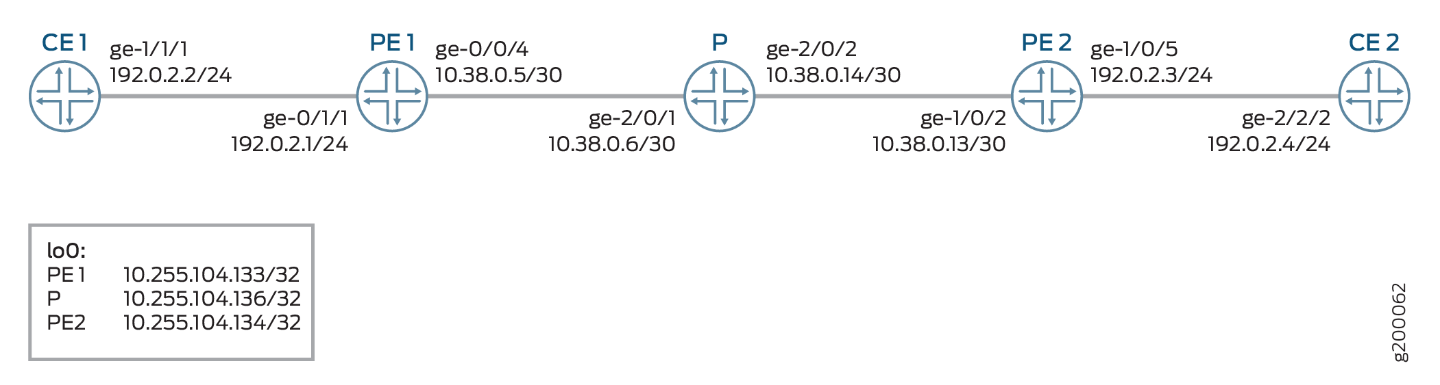
Figure 1 shows the sample topology of a Layer 2 VPN connection with chained composite next hops for MIC and MPC interfaces on MX series routers.
Configuration
CLI Quick Configuration
To quickly configure this example, copy the
following commands, paste them into a text file, remove any line breaks,
change any details necessary to match your network configuration,
and then copy and paste the commands into the CLI at the [edit] hierarchy level.
CE1
set interfaces ge-1/1/1 unit 0 family inet address 192.0.2.2/24
set interfaces ge-1/1/1 unit 0 family iso
set interfaces ge-1/1/1 unit 0 family mpls
set interfaces lo0 unit 0 family inet address 198.51.100.1/24
PE1
set interfaces ge-0/0/4 unit 0 family inet address 10.38.0.5/30
set interfaces ge-0/0/4 unit 0 family mpls
set interfaces ge-0/1/1 encapsulation ethernet-ccc
set interfaces ge-0/1/1  unit 0 family ccc
set interfaces lo0 unit 0 family inet address 10.255.104.133/32
set routing-options forwarding-table chained-composite-next-hop ingress l2vpn
set routing-options autonomous-system 200
set routing-options forwarding-table export lbpp
set protocols mpls interface ge-0/0/4.0
set protocols ospf area 0.0.0.0 interface ge-0/0/4.0
set protocols bgp group PEs type internal
set protocols bgp group PEs local-address 10.255.104.133
set protocols bgp group PEs family l2vpn signaling
set protocols bgp group PEs family inet-vpn unicast
set protocols bgp group PEs neighbor 10.255.104.134
set routing-instances vpn-a instance-type l2vpn
set routing-instances vpn-a interface ge-0/1/1.0
set routing-instances vpn-a route-distinguisher 200:1
set routing-instances vpn-a vrf-target target:200:1
set routing-instances vpn-a protocols l2vpn  encapsulation-type ethernet
 set routing-instances vpn-a protocols l2vpn site 100 site-identifier 100
set routing-instances vpn-a protocols l2vpn site 100  interface ge-0/1/1.0 remote-site-id 200
PE2
set interfaces ge-1/0/2 unit 0 family inet address 10.38.0.13/30
set interfaces ge-1/0/2 unit 0 family mpls
set interfaces ge-1/0/5 encapsulation ethernet-ccc
set interfaces ge-1/0/5 unit 0 family ccc
set interfaces lo0 unit 0 family inet address 10.255.104.134/32
set routing-options forwarding-table chained-composite-next-hop ingress l2vpn
set routing-options autonomous-system 200
set routing-options forwarding-table export lbpp
set protocols mpls interface ge-1/0/2.0
set protocols ospf area 0.0.0.0 interface ge-1/0/2.0
set protocols bgp group PEs type internal
set protocols bgp group PEs local-address 10.255.104.134
set protocols bgp group PEs family l2vpn signaling
set protocols bgp group PEs family inet-vpn unicast
set protocols bgp group PEs neighbor 10.255.104.133
set routing-instances vpn-a instance-type l2vpn
set routing-instances vpn-a interface ge-1/0/5.0
set routing-instances vpn-a route-distinguisher 200:1
set routing-instances vpn-a vrf-target target:200:1
set routing-instances vpn-a protocols l2vpn  encapsulation-type ethernet
set routing-instances vpn-a protocols l2vpn site 200 site-identifier 200
set routing-instances vpn-a protocols l2vpn site 200  interface ge-1/0/5.0 remote-site-id 100
P
set interfaces ge-2/0/1 unit 0 family inet address 10.38.0.6/30
set interfaces ge-2/0/1 unit 0 family mpls
set interfaces ge-2/0/2 unit 0 family inet address 10.38.0.14/30
set interfaces ge-2/0/2 unit 0 family mpls
set interfaces lo0 unit 0 family inet address 10.255.104.136/32
set protocols mpls interface ge-2/0/1.0
set protocols ospf area 0.0.0.0 interface ge-2/0/1.0
set protocols mpls interface ge-2/0/2.0
set protocols ospf area 0.0.0.0 interface ge-2/0/2.0
set routing-options autonomous-system 200
CE2
set interfaces ge-2/2/2 unit 0 family inet address 192.0.2.4/24
set interfaces ge-2/2/2 unit 0 family mpls
set interfaces lo0 unit 0 family inet address 198.51.100.2/24
Procedure
Step-by-Step Procedure
The following example requires you to navigate various levels in the configuration hierarchy. For information about navigating the CLI, see Using the CLI Editor in Configuration Mode.
To configure basic Layer 2 VPN with chained composite next hop on the PE1 router:
Repeat this procedure for the PE2 router in the MPLS domain, after modifying the appropriate interface names, addresses, and any other parameters for the router.
Configure the interfaces on the PE1 router.
PE1 to CE1
[edit interfaces]user@PE1# set interfaces ge-0/1/1 encapsulation ethernet-ccc user@PE1# set interfaces ge-0/1/1 unit 0 family cccPE1 to P
[edit interfaces]user@PE1 # set ge-0/0/4 unit 0 family inet address 10.38.0.5/30 user@PE1 # set ge-0/0/4 unit 0 family mplsLoopback interface
[edit interfaces]user@PE1 # set lo0 unit 0 family inet address 10.255.104.133/32Enable chained composite next hop on the global Layer 2 VPN.
[edit routing-options]use@PE1# set forwarding-table chained-composite-next-hop ingress l2vpnConfigure the autonomous system for PE1.
[edit routing-options]user@PE1# set autonomous-system 200Export the policy configured for load balancing.
[edit routing-options]user@PE1# set forwarding-table export lbppConfigure MPLS on the PE1 interfaces that connects to the P router.
[edit protocols]set mpls interface ge-0/0/4.0Configure OSPF on the PE1 nterface.
[edit protocols]user@PE1# set ospf area 0.0.0.0 interface ge-0/0/4.0Configure the IBGP group for PE1 to PE2 router.
[edit protocols]user@PE1# set bgp group PEs type internal user@PE1# set bgp group PEs local-address 10.255.104.133 user@PE1# set bgp group PEs family l2vpn signaling user@PE1# set bgp group PEs family inet-vpn unicast user@PE1# set bgp group PEs neighbor 10.255.104.134Configure the routing instance parameters.
[edit routing-instances]user@PE1# set vpn-a instance-type l2vpn user@PE1# set vpn-a interface ge-0/1/1.0 user@PE1# set vpn-a route-distinguisher 200:1 user@PE1# set vpn-a vrf-target target:200:1 user@PE1# set vpn-a protocols l2vpn encapsulation-type ethernet user@PE1# set vpn-a protocols l2vpn site 100 site-identifier 100 user@PE1# set vpn-a protocols l2vpn site 100 interface ge-0/1/1.0 remote-site-id 200
Results
From configuration mode, confirm your configuration
by entering the show chassis, show interfaces, show protocols, show routing-options, show routing-instances, and show policy-options commands.
If the output does not display the intended configuration, repeat
the instructions in this example to correct the configuration.
PE1
user@PE1# show interfaces
ge-0/0/4 {
    unit 0 {
        family inet {
            address 10.38.0.5/30;
        }
        family mpls;
    }
}
ge-0/1/1 {
    encapsulation ethernet-ccc;
    unit 0 {
        family iso;
        family mpls;
    }
}
lo0 {
    unit 0 {
        family inet {
            address 10.255.104.133/32;
        }
    }
}
user@PE1# show protocols
mpls {
    interface ge0/0/4.0;
}
bgp {
    group PEs {
        type internal;
        local-address 10.255.104.133;
        family inet-vpn {
            unicast;
        }
        family l2vpn {
            signaling;
        }
        neighbor 10.255.104.134;
    }
}
ospf {
    area 0.0.0.0 {
        interface ge-0/0/4.0;
    }
}
user@PE1# show routing-options
autonomous-system 200;
forwarding-table {
    export lbpp;
    chained-composite-next-hop {
        ingress {
            l2vpn;
        }
    }
}
user@PE1# show routing-instances
vpn-a {
    instance-type l2vpn;
    interface ge-0/1/1.0;
    route-distinguisher 200:1;
    vrf-target target:200:1;
    protocols {
        l2vpn {
            encapsulation-type ethernet;
            site 100 {
                site-identifier 100;
                interface ge-0/1/1.0 {
                    remote-site-id 200;
                }
            }
        }
    }
}