Configuring ATM Trunking on Layer 2 Circuits
You can configure Layer 2 circuits to transport ATM traffic from directly connected ATM switches across an MPLS core network. Traffic from an ATM switch is received on the local PE router. The ATM cells are given an MPLS label and then sent across the MPLS network to the remote PE router. The receiving router removes the MPLS label from the ATM cell and then forwards the cell the receiving ATM switch.
ATM trunking on Layer 2 circuits is supported only on T Series and M320 routers and ATM2 IQ PICs.
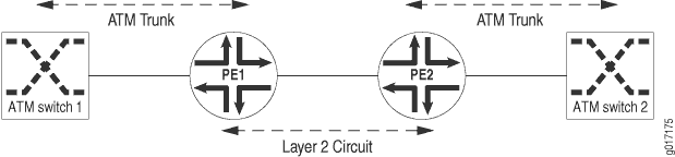
Figure 1 illustrates how ATM switches could be linked together by a Layer 2 circuit. The PE1 Router is configured to receive ATM trunk traffic from ATM Switch 1. As each ATM cell is received on the PE1 Router, it is classified by means of the class-of-service (CoS) information in the cell header and then encapsulated as a labeled packet. The CoS information and cell loss priority (CLP) of the ATM cell are copied into the experimental (EXP) bits of the MPLS label. The labeled packet is then transported across the service provider network to the PE2 Router by means of a Layer 2 circuit.
On the PE2 Router, the label is removed and the plain ATM cell is forwarded to ATM Switch 2. The CoS and CLP are extracted from the EXP bits and are then used to select the correct output queue and determine whether the ATM cell should be dropped.
The ATM physical port on the router can support 32 logical trunks when network-to-network interface (NNI) is used and 8 logical trunks when user-to-network interface (UNI) is used. A trunk can carry traffic on 32 virtual path identifiers (VPIs), numbered 0 through 31. Each ATM trunk is associated with an MPLS label and a logical interface. On the ingress router, one or more of these trunks are mapped to a Layer 2 circuit.
The configuration for the Layer 2 circuit between PE routers is conventional. Follow the procedures outlined in this chapter for configuring the circuit. However, there is some specific configuration you need to complete for the Layer 2 circuit to carry traffic from an ATM trunk.
First, enable ATM trunking for Layer 2 circuits. To enable
ATM trunking for Layer 2 circuits, specify the trunk option for the atm-l2circuit-mode statement at the [edit chassis fpc number pic number] hierarchy level:
[edit chassis fpc number pic number]
atm-l2circuit-mode trunk (uni | nni);
Specify the uni option for UNI trunks and the nni option for NNI trunks. The default option is uni.
You also need to configure each ATM trunk for a specific logical interface. Each ATM trunk has a trunk identifier in the range from 0 to 31. This configuration step is in addition to the typical configuration steps you follow related to configuring interfaces for Layer 2 circuits, as described in Configuring Interfaces for Layer 2 Circuits.
To associate a specific trunk identifier with a logical interface,
include the trunk-id statement:
trunk-id number;
You can include this statement at the following hierarchy levels:
[edit interfaces interface-name unit number][edit logical-systems logical-system-name interfaces interface-name unit number]
Since ATM trunking is supported on ATM2 IQ PICs only, the only
value you can configure for the pic-type statement is atm2. If you do not configure the pic-type statement
but you do configure the trunk option for the atm-l2circuit-mode statement (at the [chassis fpc number pic number] hierarchy level), the pic-type statement defaults to atm2.