VPLS Routing and Virtual Ports
Because VPLS carries Ethernet traffic across a service provider network, it must mimic an Ethernet network in some ways. When a PE router configured with a VPLS routing instance receives a packet from a CE device, it first determines whether it has the destination of the VPLS packet in the appropriate routing table. If it does, it forwards the packet to the appropriate PE router or CE device. If it does not, it broadcasts the packet to all other PE routers and CE devices that are members of that VPLS routing instance. In both cases, the CE device receiving the packet must be different from the one sending the packet.
In the VPLS documentation, the term router is used to refer to any device that provides routing functions.
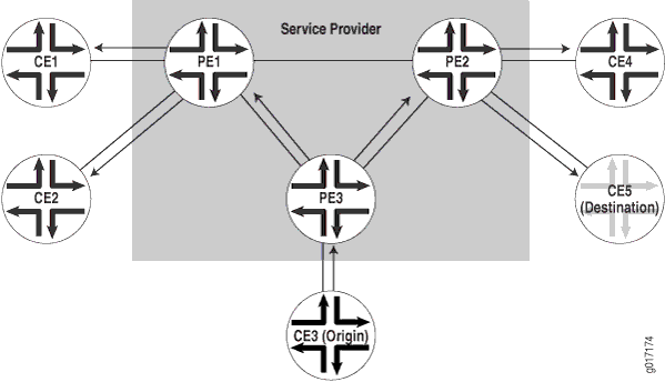
When a PE router receives a packet from another PE router, it first determines whether it has the destination of the VPLS packet in the appropriate routing table. If it does, the PE router either forwards the packet or drops it depending on whether the destination is a local or remote CE device:
-
If the destination is a local CE device, the PE router forwards the packet to it.
-
If the destination is a remote CE device (connected to another PE router), the PE router discards the packet.
If the PE router cannot determine the destination of the VPLS packet, it floods the packet to all attached CE devices.
This process is illustrated in Figure 1.
VPLS can be directly connected to an Ethernet switch. Layer 2 information gathered by an Ethernet switch (for example, media access control [MAC] addresses and interface ports) is included in the VPLS routing instance table. However, instead of all VPLS interfaces being physical switch ports, the router allows remote traffic for a VPLS instance to be delivered across an MPLS LSP and arrive on a virtual port. The virtual port emulates a local, physical port. Traffic can be learned, forwarded, or flooded to the virtual port in almost the same way as traffic is sent to a local port.
The VPLS routing table learns MAC address and interface information for both physical and virtual ports. The main difference between a physical port and a virtual port is that the router captures additional information from the virtual port, an outgoing MPLS label used to reach the remote site and an incoming MPLS label for VPLS traffic received from the remote site. The virtual port is generated dynamically on a Tunnel Services Physical Interface Card (PIC) when you configure VPLS on the router.
You can also configure VPLS without a Tunnel Services PIC. To do so, you use a label-switched interface (LSI) to provide VPLS functionality. An LSI MPLS label is used as the inner label for VPLS. This label maps to a VPLS routing instance. On the PE router, the LSI label is stripped and then mapped to a logical LSI interface. The Layer 2 Ethernet frame is then forwarded using the LSI interface to the correct VPLS routing instance.
One restriction on flooding behavior in VPLS is that traffic received from remote PE routers is never forwarded to other PE routers. This restriction helps prevent loops in the core network. However, if a CE Ethernet switch has two or more connections to the same PE router, you must enable the Spanning Tree Protocol (STP) on the CE switch to prevent loops. STP is supported on MX Series routers and EX Series switches only.
The Junos OS allows standard Bridge Protocol Data Unit (BPDU) frames to pass through emulated Layer 2 connections, such as those configured with Layer 2 VPNs, Layer 2 circuits, and VPLS routing instances. However, CE Ethernet switches that generate proprietary BPDU frames might not be able to run STP across Juniper Networks routing platforms configured for these emulated Layer 2 connections.
Under certain circumstances, VPLS provider routers might duplicate an Internet Control Message Protocol (ICMP) reply from a CE router when a PE router has to flood an ICMP request because the destination MAC address has not yet been learned. The duplicate ICMP reply can be triggered when a CE router with promiscuous mode enabled is connected to a PE router. The PE router automatically floods the promiscuous mode–enabled CE router, which then returns the ICMP request to the VPLS provider routers. The VPLS provider routers consider the ICMP request to be new and flood the request again, creating a duplicate ping reply.