Interoperability Between BGP Signaling and LDP Signaling in VPLS
You can configure a VPLS routing instance where some of the PE routers use BGP for signaling and some use LDP for signaling.
In the VPLS documentation, the word router in terms such as PE router is used to refer to any device that provides routing functions.
The following concepts form the basis of the configuration needed to include both BGP-signaled and LDP-signaled PE routers in a VPLS routing instance:
PE router mesh group—Consists of a set of routers participating in a VPLS routing instance that share the same signaling protocol, either BGP or LDP, and are also fully meshed. Each VPLS routing instance can have just one BGP mesh group. However, you can configure multiple LDP mesh groups for each routing instance.
Border router—A PE router that must be reachable by all of the other PE routers participating in a VPLS routing instance, whether they are LDP-signaled or BGP-signaled. Bidirectional pseudowires are created between the border router and all of these PE routers. The border router is aware of the composition of each PE mesh group configured as a part of the VPLS routing instance. It can also have direct connections to local CE routers, allowing it to act as a typical PE router in a VPLS routing instance.
The following sections describe how the LDP-signaled and BGP-signaled PE routers function when configured to interoperate within a VPLS routing instance:
LDP-Signaled and BGP-Signaled PE Router Topology
Figure 1 illustrates a topology for a VPLS routing instance configured to support both BGP and LDP signaling. Router B is the border router. Routers PE1 and PE2 are in the LDP-signaled mesh group LDP-1. Routers PE3, PE4, and PE5 are in the LDP-signaled mesh group LDP-2. Routers PE6, PE7, PE8, and router B (the border router) are in the BGP-signaled mesh group. The border router also acts as a standard VPLS PE router (having local connections to CE routers). All of the PE routers shown are within the same VPLS routing instance.
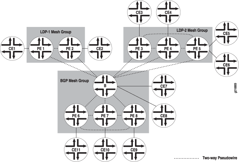
Two-way pseudowires are established between the PE routers in each mesh group and between each PE router in the VPLS routing instance and the border router. In Figure 1, two-way pseudowires are established between routers PE1 and PE2 in mesh group LDP-1, routers PE3, PE4, and PE5 in mesh group LDP-2, and routers PE6, PE7, and PE8 in the BGP mesh group. Routers PE1 through PE8 also all have two-way pseudowires to the Border router. Based on this topology, the LDP-signaled routers are able to interoperate with the BGP-signaled routers. Both the LDP-signaled and BGP-signaled PE routers can logically function within a single VPLS routing instance.
The following features are not supported for VPLS routing instances configured with both BGP and LDP signaling:
Point-to-multipoint LSPs
Integrated routing and bridging
IGMP snooping
Flooding Unknown Packets Across Mesh Groups
Broadcast, multicast, and unicast packets of unknown origin received from a PE router are flooded to all local CE routers. They are also flooded to all of the PE routers in the VPLS routing instance except the PE routers that are a part of the originating PE router mesh group.
For example, if a multicast packet is received by the border router in Figure 1, it is flooded to the two local CE routers. It is also flooded to routers PE1 and PE2 in the LDP-1 mesh group and to routers PE3, PE4, and PE5 in the LDP-2 mesh group. However, the packet is not flooded to routers PE6, PE7, and PE8 in the BGP mesh group.
Unicast Packet Forwarding
The PE border router is made aware of the composition of each PE router mesh group. From the data plane, each PE router mesh group is viewed as a virtual pseudowire LAN. The border router is configured to interconnect all of the PE router mesh groups belonging to a single VPLS routing instance. To interconnect the mesh groups, a common MAC table is created on the border router.
Unicast packets originating within a mesh group are dropped if the destination is another PE router within the same mesh group. However, if the destination MAC address of the unicast packet is a PE router located in a different mesh group, the packet is forwarded to that PE router.