Configure Hot-Standby Pseudowire Redundancy in H-VPLS
Hot-standby redundant pseudowire provide redundant end-to-end paths on an H-VPLS network. When you enable hot-standby redundancy and the primary pseudowire fails, the network transitions to the redundant pseudowire with minimal disruption.
The benefits of hot-standby pseudowire for H-VPLS include the following:
-
Rapid recovery to a rerouted path when the active path has a failure.
-
Reduced traffic disruption during the transition.
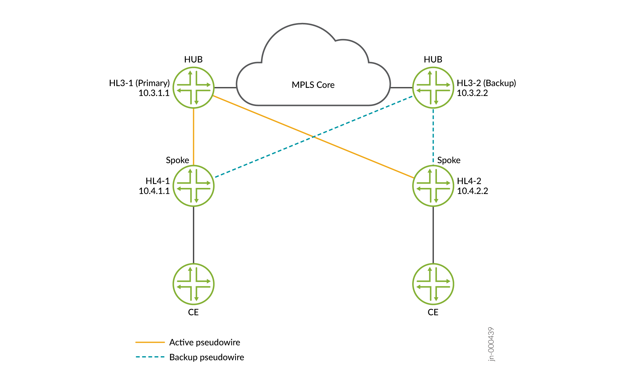
Figure 1 shows a simplified 2-level hierarchical VPLS (H-VPLS) network with an active pseudowire connecting the primary hub HL3-1 to spokes HL4-1 and HL4-2. A standby pseudowire connects the backup hub HL3-2 to spokes HL4-1 and HL4-2. When the primary pseudowire fails, the standby pseudowire takes over.
With the hot-standby enabled, both the primary and backup hub have programmed active and standby pseudowire paths to spoke devices in the Packet Forwarding Engine. Likewise, the spoke devices have programmed active and standby pseudowire paths. Having both active and pseudowire paths preprogrammed on the Packet Forwarding Engine reduces the amount of traffic that gets discarded during transition. Both the active and standby pseudowire can send and receive traffic. So we must give special consideration to preventing traffic loops when spoke devices send unknown traffic. To configure hot-standby in an H-VPLS network, configure the following statements on all hub-and-spoke devices:
On the hub devices:
-
Include the
pseudowire-status-tlvstatement at the[edit routing-instances routing-instance-name protocols vpls mesh-group mesh-group-name neighbor address ]hierarchy. PE devices use the pseudowire status type length variable (TLV) to communicate the pseudowire status. -
Include the
This allows the backup hub device managing the standby pseudowire to preprogram pseudowire paths to the spoke devices.hot-standby-vc-onstatement at the[edit routing-instances routing-instance-name protocols vpls mesh-group mesh-group-name neighbor address pseudowire-status-tlv]hierarchy on the hub devices. -
Include the
load-balance per-packetstatement at the[edit policy-options policy-statement policy-name term term-name then]hierarchy and apply the routing policy to all routes in the forwarding table.
On the spoke devices:
-
Include the
pseudowire-status-tlvstatement at the[edit routing-instances routing-instance-name protocols vpls neighbor address ]hierarchy. PE devices use the pseudowire status type length variable (TLV) to communicate the pseudowire status. -
Include the
hot-standbystatement at the [edit routing-instances routing-instance-name protocols vpls neighbor address backup-neighbor address]hierarchy on the spoke devices. Enablinghot-standbyallows the spoke devices to preprogram the routes and next hops of the standby pseudowire. -
Include the
vpls-hot-standby-convergencestatement at the[ routing-options forwarding-table]hierarchy on the spoke device. When you enablevpls-hot-standby-convergence, the Junos device sends advertising messages with different labels on the active and standby pseudowire. The spoke device can then differentiate the return messages coming back from the active and standby pseudowire. -
Include the
load-balance per-packetstatement at the[edit policy-options policy-statement policy-name term term-name then]hierarchy level and apply the routing policy to all routes in the forwarding table. -
(Optional) In some cases, you may want to include a
switchover-delayat the[edit routing-instances routing-instance-name protocols vpls mesh-group mesh-group-name neighbor address ]hierarchy on the spoke device. This is the time that the device waits before switching to the backup neighbor after detecting a failure in the primary pseudowire connection. We recommend a delay of 60 seconds.
The following sample hot-standby configuration shows how to configure the hub-and-spoke devices.
The following is the sample configuration for Hub HL3-1.
routing-instances
    LDP-VPLS {
        instance-type vpls;
        interface ge-0/0/0.0;
        protocols {
            vpls {
                no-tunnel-services;
                vpls-id 1;
                neighbor 10.3.2.2;
                mesh-group HL4 {
                    vpls-id 1;
                    local-switching;
                    neighbor 10.4.1.1 {
                        pseudowire-status-tlv hot-standby-vc-on;
                    }
                    neighbor 10.4.2.2 {
                        pseudowire-status-tlv hot-standby-vc-on;
                    }
                }
                connectivity-type permanent;
            }
        }
}policy-options {
policy-statement PPLB {
then {
load-balance per-packet;
}
}
}
routing-options {
forwarding-table {
export PPLB;
}
}The following is the sample configuration for Hub HL3-2.
routing-instances
LDP-VPLS {
instance-type vpls;
protocols {
vpls {
enable-mac-move-action;
no-tunnel-services;
vpls-id 1;
neighbor 10.1.2.2;
mesh-group HL4 {
vpls-id 1;
local-switching;
neighbor 10.4.1.1 {
pseudowire-status-tlv hot-standby-vc-on;
}
neighbor 10.4.2.2 {
pseudowire-status-tlv hot-standby-vc-on;
}
}
connectivity-type permanent;
}
}
}
policy-options {
    policy-statement PPLB {
        then {
            load-balance per-packet;
        }
    }
}
routing-options {
    forwarding-table {
        export PPLB;
    }
}
The following is the sample configuration for the spoke devices (HL4-1 and HL4-2).
routing-instances
    LDP-VPLS {
        instance-type vpls;
        interface ge-0/0/0.0;
        protocols {
            vpls {
                no-tunnel-services;
                vpls-id 1;
                neighbor 10.3.1.1 {
                    pseudowire-status-tlv;
                    switchover-delay 60000;
                    revert-time 10;
                    backup-neighbor 10.3.2.2 {
                        hot-standby;
                    }
                }
            }
        }
    }

routing-options {
    forwarding-table {
        vpls-hot-standby-convergence;
    }
}policy-options {
policy-statement PPLB {
then {
load-balance per-packet;
}
}
}
routing-options {
forwarding-table {
export PPLB;
}
}