Pinging Customer Edge Device IP Address
In a virtual private LAN service (VPLS), hierarchical VPLS (H-VPLS), and Ethernet VPN (EVPN) network, you can test the connectivity to a given customer edge (CE) IP address to get the CE device’s MAC address and attachment points (name of the provider edge [PE] device and local interfaces) to the provider network. This is beneficial in Layer 2 VPN technologies, which have a large number of PE devices and for which getting connectivity information about customers is a challenge.
The capability to ping CE IP address has the following use cases and feature support:
VPLS or EVPN Use Case
In older Junos OS releases, the ping utility for VPLS was for destination MAC addresses. Modern Junos OS releases support the CE-IP ping utility, which is based on the LSP ping infrastructure defined in RFC 4379. With the CE-IP ping feature, the ping utility is enhanced with the capability to ping an IP address for a VPLS and EVPN network. Separate unicast LSP ping echo requests are sent to all neighboring PE devices, and only one PE device responds back with the information about the CE device.
Figure 1 illustrates a use case for implementing the CE-IP ping feature in a VPLS or EVPN network. There are three PE devices—Devices PE1, PE2, and PE3—connected to four customer sites—Devices CE1, CE2, CE3, and CE4. In this use case, Device PE1 tests the connectivity to an IP host— 10.0.0.2 —to get the MAC address and attachment point of the host in the VPLS or EVPN service provider network for a specific routing instance. This is done using the ce-ip command. The command output displays the required information depending on the type of routing instance configured.
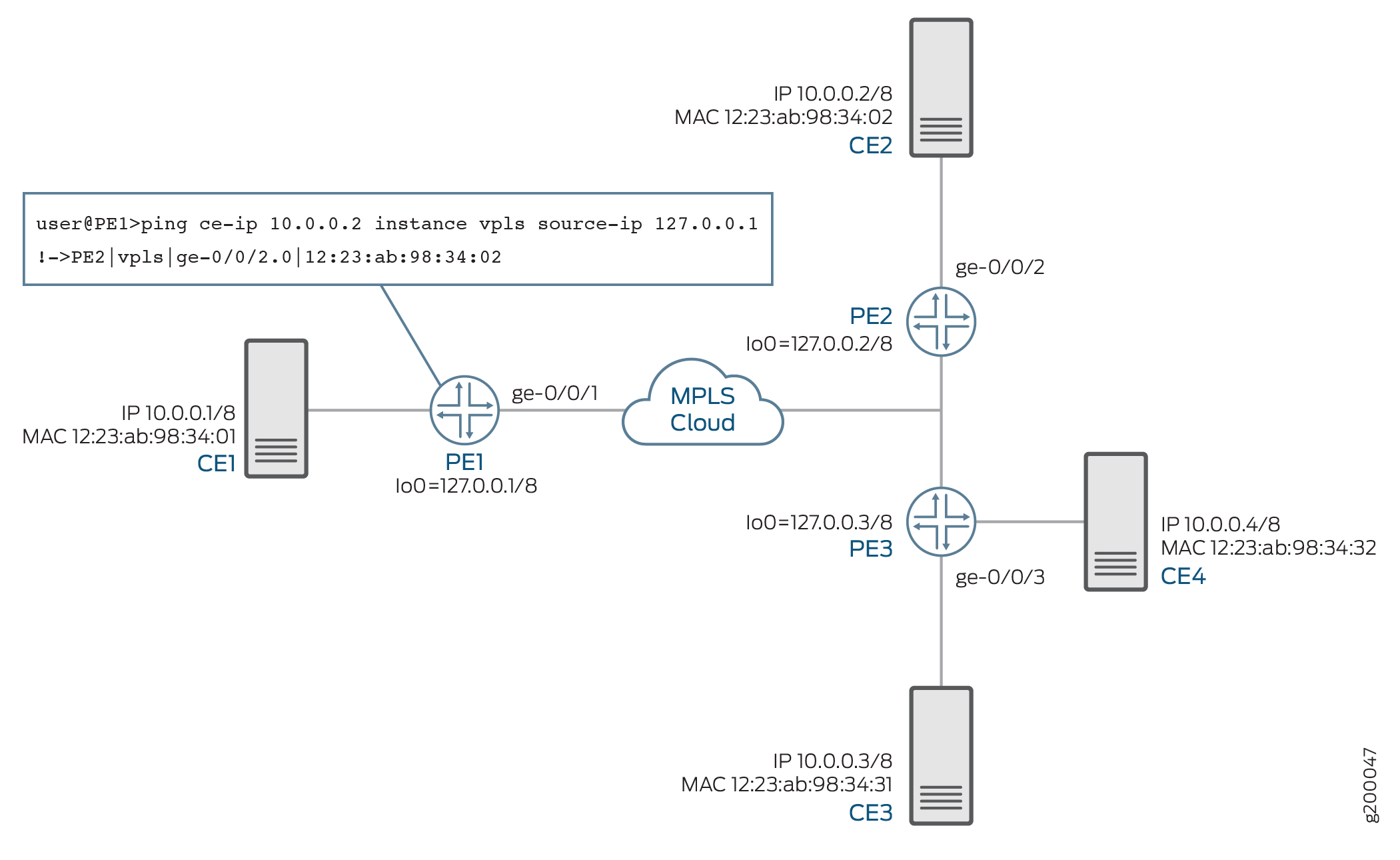
When the ce-ip ping command is executed in a VPLS or EVPN network, the packet flow is as follows:
1—LSP ping echo request
The
ce-ipLSP ping echo request packet is sent using the data plane.Device PE1 sends an LSP ping echo request to all the neighboring PE devices, Devices PE2 and PE3. The IP address to the target host is carried in the LSP ping echo request using type, length, and value (TLV).
2—ARP request
Remote PE devices send host-injected Address Resolution Protocol (ARP) requests on all the CE-facing interfaces for the destination IP address. The ARP request is sent to the host 10.0.0.2 from Device PE2 to Device CE2 and from Device PE3 to Devices CE3 and CE4. The source IP address in the ARP request is set to 0.0.0.0 by default.
3—ARP response
Device CE2 responds to the ARP request from Device PE2.
4—LSP ping echo response
If an ARP response is received from a CE device, the remote PE device responds to the PE device initiating the ARP request with the MAC address and attachment point encoded as TLV in the LSP ping echo response packet.
The
ce-ipLSP ping echo response packet is sent using IP/UDP protocol in the control plane.Device PE2 sends an LSP ping response to Device PE1. The other remote PE device, Device PE3, does not respond to the LSP ping because an ARP response is not received from Device CE3.
The output of the
ce-ipping command on Device PE1 displays the information that is received from the LSP ping response.
H-VPLS Use Case
In a VPLS or EVPN network, all the PE devices are connected in a mesh topology and therefore the devices are reachable to each other through one hop in terms of virtual circuit label reachability. However, in an H-VPLS network, there are spoke PE devices connected to the VPLS full-mesh network. These spoke PE devices cannot be reached by the remote PE devices through one hop. Because the VPLS ping feature always uses a virtual circuit label TTL value of one, the ping packets are received by the control plane in all the PE devices that are one hop away. The control plane then reinjects the ping packets to the next hop (that is, the spoke PE device) in the H-VPLS network for the ping packet to reach all the PE devices.
Figure 2 illustrates a use case for implementing the CE-IP ping feature in an H-VPLS network. There are three PE devices—Devices PE1, PE2, and PE3—connected to four customer sites—Devices CE1, CE2, CE3, and CE4. Device PE3 is connected to an H-VPLS spoke that connects to Device CE4. In this use case, Device PE1 tests the connectivity to an IP host— 10.0.0.4 —to get the MAC address and attachment point of the host in the H-VPLS service provider network using the ce-ip command.
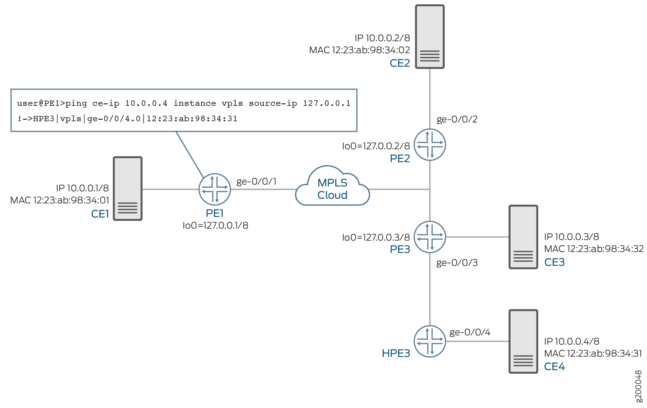
When the ce-ip ping command is executed in an H-VPLS network, the packet flow is as follows:
1—LSP ping echo request
The
ce-ipLSP ping echo request packet is sent using the data plane.Device PE1 sends an LSP ping echo request to all the neighboring PE devices, Devices PE2 and PE3. The IP address to the target host is carried in the LSP ping echo request using type, length, and value (TLV).
1A—LSP re-injected ping request
Device PE3 re-injects the LSP ping request to the spoke PE device, Device HPE3.
2—ARP request
The remote PE devices, Devices PE2 and PE3, and the spoke PE device, Device HPE3, send host-injected ARP requests on all the CE-facing interfaces for the destination IP address. The ARP request is sent to the host 10.0.0.4. The source IP address in the ARP request is set to 0.0.0.0 by default.
3—ARP response
Device CE4 responds to the ARP request from Device HPE3.
4—LSP ping echo response
If an ARP response is received from a CE device, the remote PE device responds to the PE device initiating the ARP request with the MAC address and attachment point encoded as TLV in the LSP ping echo response packet.
The
ce-ipLSP ping echo response packet is sent using IP/UDP protocol in the control plane.Device HPE3 sends an LSP ping response to Device PE1. The other remote PE devices, Device PE2 and PE3, do not respond to the LSP ping because they do not receive an ARP response from the CE device.
Supported and Unsupported Features for CE-IP Ping
The following features are supported with the CE-IP address ping feature:
The CE-IP ping feature in a VPLS or H-VPLS network is supported on routing instance type VPLS only
The CE-IP ping feature in an EVPN network is supported on routing instance type EVPN only.
Support for VPLS and EVPN hybrid routing instances, where the routing instance type is EVPN and the CE-IP ping support is available on single-homing seamless migration nodes with LDP-VPLS only.
The CE-IP ping feature has the following considerations and limitations:
If the CE destination IP address that is being pinged is behind the very same PE device where the ping command is issued, the ce-ip ping functionality does not work.
The LSP ping echo response packet is always sent using the IP/UDP protocol in the control plane. This requires that the PE devices are IP reachable to each other for the feature to work.
The CE-IP feature does not provide support for the following:
Virtual switch routing instance
IPv6 addresses
Logical systems
Integrated routing and bridging (IRB) configured in the EVPN or VPLS routing instance