Next-Generation VPLS Point-to-Multipoint Forwarding Overview
VPLS is a Layer 2 solution for efficiently sending multicast traffic over a multiprotocol label switching (MPLS) core.
VPLS emulates the broadcast domain of a LAN across an MPLS network cloud. Traditional MPLS implementations of VPLS require that all participating ingress provider edge (PE) routers make separate copies of each broadcast or multicast packet to send to all other PE routers that are part of the VPLS site for the same extended LAN. In a large virtual private network (VPN), replication overhead can be significant for each ingress router and its attached core-facing links.
Juniper Networks has several important VPLS enhancements that provide a solution for the replication overhead issue:
Point-to-multipoint LSP support provides efficient distribution of multicast traffic such as IP-based television (IPTV).
Multihoming support integrates the path selection capability of BGP with VPLS to allow a customer edge (CE) Ethernet switch to have a backup path across the network.
This document explains the use of point-to-multipoint LSPs in the MPLS core as an alternative to ingress replication. Point-to-multipoint LSPs enable ingress routers to send only one copy of each packet into the MPLS cloud. Each PE router maintains a point-to-multipoint tree so traffic can be efficiently sent to all VPN sites. This process requires the fewest possible replications of the packets and does the replication at the most optimal points in the network.
The benefits of this approach are:
Conservation of bandwidth
Increased PE router efficiency
Improved traffic engineering for flows of flooded traffic
Manual control or several levels of automatic operation
Simplified multicast optimization, which is ideal for IPTV or network access wholesale
The Internet Engineering Task Force (IETF) supports two standardized VPLS implementations: RFC 4761: Virtual Private LAN Service (VPLS) Using BGP for Auto-Discovery and Signaling and RFC 4762: Virtual Private LAN Service (VPLS) Using LDP Signaling.
Juniper Networks has implemented VPLS solutions based on both RFCs. BGP-based VPLS is the superior solution, but LDP-based VPLS is supported for those service providers that have already deployed this alternative.
For a detailed technology overview of LDP-BGP VPLS interworking see LDP-BGP VPLS Interworking at https://www.juniper.net/us/en/local/pdf/whitepapers/2000282-en.pdf.
Next-Generation VPLS Point-to-Multipoint Forwarding Applications
VPLS provides a multipoint-to-multipoint Ethernet service that can span one or more metro areas and provides connectivity between multiple sites as if these sites were attached to the same Ethernet LAN.
VPLS uses an IP and MPLS service provider infrastructure. From a service provider’s point of view, use of IP and MPLS routing protocols and procedures instead of the Spanning Tree Protocol (STP), and MPLS labels instead of VLAN IDs, significantly improves the scalability of the VPLS service.
VPLS Protocol Operation
VPLS carries Ethernet traffic across a service provider network, so it must mimic an Ethernet network in some ways. When a PE router configured with a VPLS routing instance receives a packet from a CE device, it first determines whether it knows the destination of the VPLS packet. If it does, it forwards the packet to the appropriate PE router or CE device. If it does not, it broadcasts the packet to all the other PE routers and CE devices that are members of that VPLS routing instance. In both cases, the CE device receiving the packet must be different from the one sending the packet.
When a PE router receives a packet from another PE router, it first determines whether it knows the destination of the VPLS packet. If the destination is known, the PE router either forwards the packet or drops it, depending on whether the destination is a local or remote CE device. The PE router has three options (scenarios):
If the destination is a local CE device, the PE router forwards the packet to it.
If the destination is a remote CE device (connected to another PE router), it discards the packet.
If it cannot determine the destination of the VPLS packet, the PE router floods it to its attached CE devices.
A VPLS can be directly connected to an Ethernet switch. Layer 2 information gathered by an Ethernet switch, such as media access control (MAC) addresses and interface ports, is included in the VPLS routing instance table. However, instead of all VPLS interfaces being physical switch ports, the router allows remote traffic for a VPLS instance to be delivered across an MPLS LSP and arrive on a virtual port. The virtual port emulates a local, physical port. Traffic can be learned, forwarded, or flooded to the virtual port in almost the same way as traffic sent to a local port.
The VPLS routing table is populated with MAC addresses and interface information for both physical and virtual ports. One difference between a physical port and a virtual port is that on a virtual port, the router captures the outgoing MPLS label used to reach the remote site and an incoming MPLS label for VPLS traffic received from the remote site. The virtual port is generated dynamically on a Tunnel Services PIC when you configure VPLS on a router that is using a Tunnel Services PIC. A Tunnel Services PIC is required to configure a VPLS router on some routers running Junos OS.
If your router has an Enhanced FPC installed, you can configure VPLS without a Tunnel Services PIC. To do so, you use a label-switched interface (LSI) to provide VPLS functionality. An LSI MPLS label is used as the inner label for VPLS. This label maps to a VPLS routing instance. On the PE router, the LSI label is stripped and then mapped to a logical LSI interface. The Layer 2 Ethernet frame is then forwarded using the LSI interface to the correct VPLS routing instance. To configure VPLS on a router without a Tunnel Services PIC, include the no-tunnel-services statement.
One restriction on flooding behavior in VPLS is that traffic received from remote PE routers is never forwarded to other PE routers. This restriction helps prevent loops in the core network. This also means that the core network of PE routers must be fully meshed. Additionally, if a CE Ethernet switch has two or more connections to the same PE router, you must enable the Spanning Tree Protocol (STP) on the CE switch to prevent loops.
Point-to-Multipoint Implementation
In next-generation VPLS, point-to-multipoint LSPs are used to flood broadcast, multicast, and unknown unicast traffic across a VPLS core network to all the PE routers. This is more efficient in terms of bandwidth utilization between the PE router and provider (P) router.
If point-to-multipoint LSPs are not being used, the PE router needs to forward multiple copies of broadcast, multicast, and unknown unicast packets to all PE routers. If point-to-multipoint LSPs are used, the PE router floods one copy of each packet to the P router, where it is replicated close to the egress router.
For next-generation VPLS, both point-to-point LSPs and point-to-multipoint LSPs are needed between the PE routers.
In VPLS, point-to-multipoint LSPs are only used to transport broadcast frames, multicast frames, and unicast frames with an unknown destination MAC address. All other frames are still transported using point to-point LSPs. This structure is much more efficient for bandwidth use, particularly near the source of the broadcast, multicast, and unknown frames. However, it also results in more state in the network because each PE router is the ingress of one point-to-multipoint LSP that touches all other PE routers and one point-to-point LSP going to each of the other PE routers.
Enabling point-to-multipoint LSPs for any VPLS instance starts the flooding of unknown-unicast, broadcast, and multicast traffic using point-to-multipoint LSPs.
For each VPLS instance, a PE router creates a dedicated point-to-multipoint LSP. Whenever VPLS discovers a new neighbor through BGP, a source-to-leaf sub-LSP is added for this neighbor in the point-to-multipoint LSP instance.
If there are n PE routers in the VPLS instance, then the discovery of a new neighbor through BGP creates n point-to-multipoint LSPs in the network, where each PE router is the root of the tree and the rest of the n-1 PE routers are leaf nodes (or source-to-leaf sub-LSPs).
Each point-to-multipoint LSP created by PE routers can be identified using an RSVP-traffic engineering point-to-multipoint session object, which is passed as a provider multicast service interface (PMSI) tunnel attribute by BGP while advertising VPLS routes. Using this tunnel attribute, incoming source-to-leaf sub-LSP add request messages (RSVP-path message) can be associated with the right VPLS instance and originator PE router. As a result, label allocation is done in such a way that when traffic arrives on the LSP, it is not only terminated on the right VPLS instance, but the originator PE router is also identified so that source MAC addresses can be learned.
Point-to-multipoint LSPs can be enabled incrementally on any PE router that is part of a specific VPLS instance. This means a PE router that has this feature uses point-to-multipoint LSPs to flood traffic, whereas other PE routers in the same VPLS instance can use ingress replication to flood the traffic. However, when point-to-multipoint LSPs are enabled on any PE router, make sure that all the PE routers that are part of the same VPLS instance also support this feature.
Penultimate-hop popping (PHP) is disabled for point-to-multipoint LSPs terminating in a VPLS instance.
Limitations of Point-to-Multipoint LSPs
When implementing point-to-multipoint LSPs remember the following limitations:
There is no mechanism to allow only multicast traffic to go over the point-to-multipoint LSP.
Point-to-multipoint LSPs do not support inter-AS traffic. Only intra-AS traffic is supported.
Point-to-multipoint LSPs do not support graceful restart for ingress LSPs. This also affects VPLS when flooding is done using point-to-multipoint LSPs.
The same point-to-multipoint LSP cannot be shared across multiple VPLS instances.
When this feature is enabled, ingress PE routers use only point-to-multipoint LSPs for flooding. The router initiates the creation of source-to-leaf sub-LSPs for each PE router that is part of the same VPLS instance. Any PE router for which this source-to-leaf sub-LSP fails to come up does not receive any flooded traffic from the ingress PE router.
It is possible that flooding of unknown unicast traffic over point-to-multipoint LSPs may lead to packet reordering, because as soon as learning is done, unicast traffic is sent out using point-to-point pseudowire LSPs.
Static LSPs and LSPs configured using the
label-switched-path-templatestatement cannot be configured at the same time.When an LSP is configured using the
static-lspstatement, a point-to-multipoint LSP is created statically to include all neighbors in the VPLS instance.
Before enabling the point-to-multipoint LSP feature on any PE router, make sure that all the other PE routers that are part of the same VPLS instance are upgraded to a Junos OS Release that supports it. If a router in the VPLS instance does not support point-to-multipoint LSPs, it may lose all the traffic sent on the point-to-multipoint LSP. Therefore, do not enable this feature if there is a single router in a VPLS instance that is not capable of supporting this feature, either because it is not running the appropriate Junos OS Release or because it is a router from a vendor that does not support this feature.
Simultaneous Transit and Egress Router Operation
A PE router that plays the role of both an MPLS transit router and an MPLS egress router can do so by receiving either one or two copies of a packet to fulfill each of its roles.
To fulfill both roles while using only a single copy of a packet, some Juniper Networks routers require a Tunnel Services PIC configured with virtual tunnel (vt) interfaces and ultimate-hop popping must be enabled. With a virtual tunnel interface and ultimate-hop popping, a single copy of the received packet is forwarded beyond the PE router to fulfill the transit router role and is also consumed internally by the virtual tunnel interface to fulfill the egress router role.
If a label-switched interface (LSI) logical interface is used, then two copies of each packet must be received on the point-to-multipoint LSP, one to fulfill the transit router role and one to fulfill the egress router role.
Implementation
Some implementations of VPLS use ingress replication. Ingress replication is simple but inefficient. It sends multiple copies of the same packet on a link, especially the PE-P link. This causes wasted bandwidth when there is a heavy broadcast and multicast traffic.
As shown in the sample network in Figure 1 the ingress PE router makes three copies of every broadcast, multicast, and flooded packet for each VPLS instance.
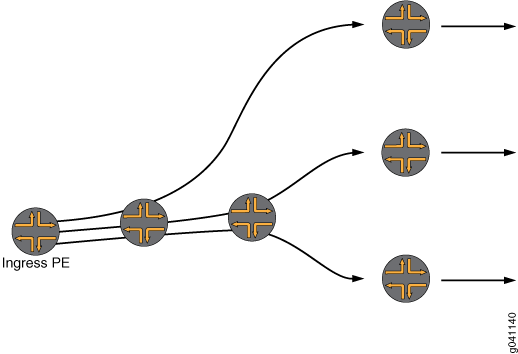
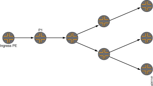
Figure 2 shows how a point-to-multipoint LSP works for multicast.
In a VPLS using point-to-multipoint LSPs, the ingress PE router sends a single copy of the multicast packet to Router P1. Router P1 makes two copies for this point-to-multipoint LSP. Each of the other P routers also makes multiple copies of the packet. This moves replication closer to the endpoints and results in significant improvements in the network bandwidth utilization.