Configuring Aggregated Ethernet Interfaces for Layer 2 Circuits
Configure AE interfaces for Layer 2 circuits. Link aggregation enhances your network resilience and increases bandwidth capacity.
Overview
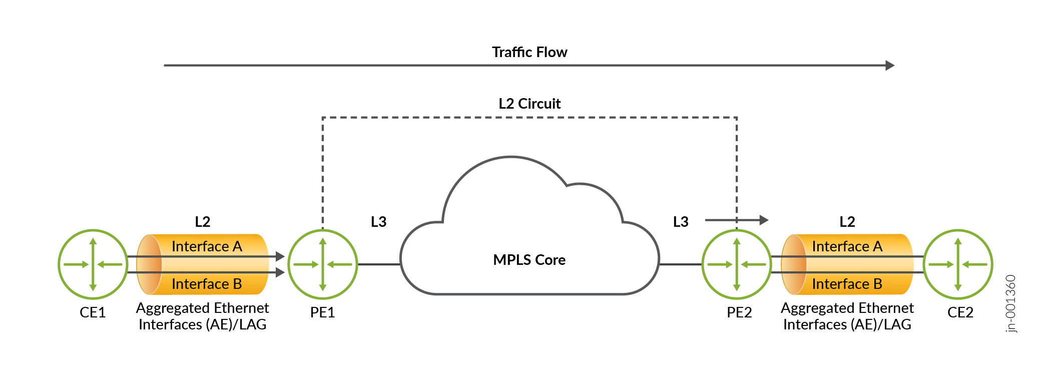
Layer 2 Circuit functionality enables Layer 2 Ethernet frames to be transmitted over an IP-MPLS core. The provides seamless Layer 2 connectivity between geographically separated locations. Configuring Aggregated Ethernet (AE) interfaces for a Layer 2 Circuit topology allows you to leverage link aggregation for enhanced resilience and increased bandwidth capacity. Traffic is load-balanced across the individual links within the AE interface when being sent to the Customer Edge (CE) device. You will use existing CLI commands for configuration.
Benefits of Aggregated Ethernet interfaces over Layer 2 Circuits
-
Enhances network resilience by combining multiple physical links into a single logical link, reducing the impact of individual link failures.
-
Higher data throughput and improved network performance.
-
Optimized traffic distribution through load balancing.
-
Simplified network management by using existing CLI commands for configuration, making it easier to set up and maintain L2 circuits on AE interfaces.
Configuring Aggregated Ethernet for Layer 2 Circuits
To configure an AE interface for an L2 Circuit, start by configuring the AE interface with
an encapsulation type for your network. You can use either ethernet-ccc or
vlan-ccc.
flexible-ethernet-services with vlan-ccc
encapsulation.-
[edit interfaces aeinterface-number encapsulation
                encapsulation-type]
Finally, configure the circuit in the L2 Circuit protocols hierarchy. You will use the neighbor's IP address, the AE interface, and the virtual circuit ID:
-
[set protocols l2circuit neighbor neighbor-ip-address
              interface aeinterface-number


                     virtual-circuit-number virtual-circuit-id
                virtual-circuit-id]