Extension of Pseudowire Redundancy Condition Logic to Pseudowire Service Logical Interface Overview
The pseudowire redundancy feature for mobile backhaul scenarios uses logical tunnel (lt-) paired interfaces as the stitching between Layer 2 and Layer 3 domains. This feature now includes the MPLS pseudowire service logical interface to terminate subscriber interfaces using the ps0.0 interface as the stitching between Layer 2 and Layer 3 domains. This topic describes the functional details of the pseudowire redundancy feature using the ps0.0 interface, which extends the policy logic used in the logical tunnel interfaces.
A pseudowire logical device and its related pseudowire logical interfaces are dependent on the state of the underlying logical transport interface device, which is either the Layer 2 VPN or Layer 2 circuit.
We recommend that you use unit 0 to represent
the transport logical interface for the pseudowire device. Non-zero
unit numbers represent service logical interfaces
used for pseudowire subscriber interfaces.
Sample Topology
Figure 1 on page 1 shows the stitching of Layer 2 and Layer 3 domains between the MPLS access node and the MPLS core. The primary or backup pseudowire on the MPLS access side is terminated at the provider edge devices (PE1 and PE2) at the pseudowire logical transport interface (ps0.0). The corresponding pseudowire logical service interfaces (ps0.1 to ps0.n) at the core MPLS cloud are connected to the Layer 3 domain, and these pseudowire logical service interfaces are configured in Layer 3 VPN routing instances.
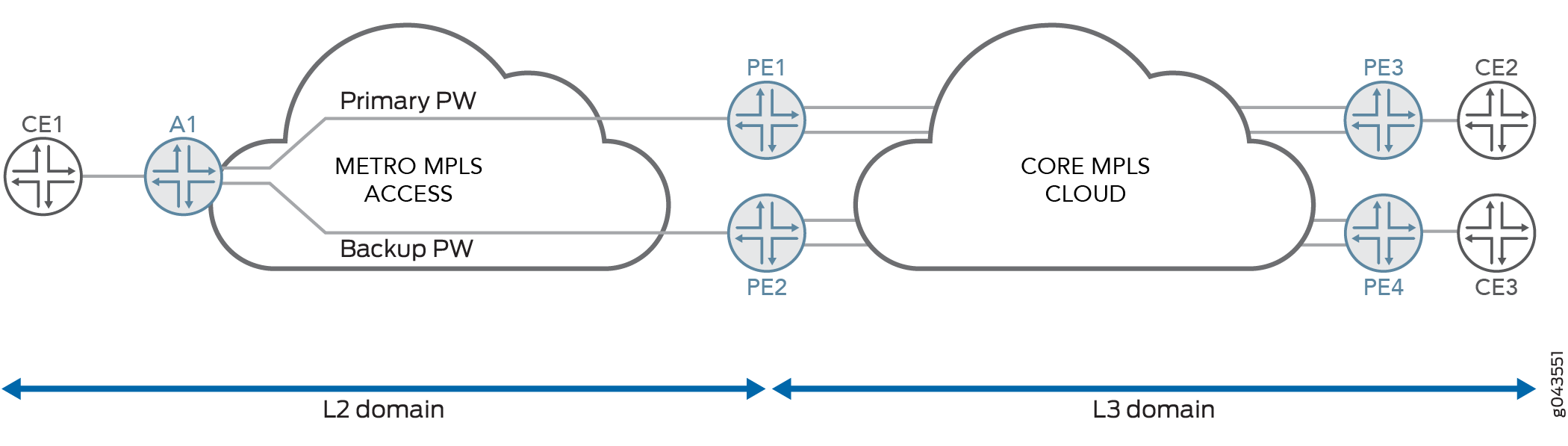
This topology results in a Layer 2 circuit across the MPLS access node and provider edge routers, with the pseudowire logical transport interface (ps0.0) acting as the local interface of the Layer 2 circuit terminating at the PE routers.
Functionality
Figure 1 on page 1 shows the functional details of pseudowire redundancy with events between the devices. A1 is the MPLS access node that initiates the primary and backup Layer 2 circuits to the provider edge devices (PE1 and PE2). The Layer 2 circuit is terminated on provider edge devices and then stitched to the Layer 3 VPN.
The functional flow is as follows:
-
Create the primary and backup Layer 2 circuit at access node A1.
-
Detect both the primary and backup path, advertise the local preference, and stitch the Layer 2 circuit and Layer 3 VPN at the provider edge devices (PE1 and PE2).
The following pseudowire code is used to notify the standby status from the access node to provider edge devices:
-
L2CKT_PW_STATUS_PW_FWD_STDBY flag with 0x00000020.
Policy Condition for Pseudowire Service Logical Interfaces
The policy condition uses pseudowire service logical interfaces to stitch the Layer 2 and Layer 3 domains. Provider edge devices (PE1 and PE2) detect both primary and standby virtual circuits on the metro MPLS side. The primary virtual circuit is stitched to Layer 3 domain at the services side PE1 and PE2 towards the MPLS core. See Figure 2 on page 2.
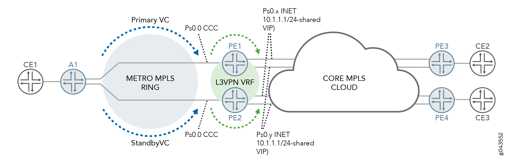
A primary Layer 2 circuit exists between access node A1 and provider edge device PE1, and a standby Layer 2 circuit exists between the same access node A1 and provider edge device PE2. The pseudowire service on the transport logical interface (ps0.0) is the local interface for the Layer 2 circuit at PE1 and PE2. At PE1 and PE2, there are multiple Layer 3 VPN instances; for example vrf-x and vrf-y.
The pseudowire service on service logical interfaces ps0.x and ps0.y are configured for the vrf-x and vrf-y routing instances respectively. For example, when the traffic with VLAN ID x originates from the access node to PE1 or PE2 on the Layer 2 circuit, it exits through the pseudowire service on the transport logical interface (ps0.0). Then the pseudowire service on service logical interface ps0.x is selected and sent through the vrf-x instance.
When the pseudowire state is active, the aggregation provider edge device (PE1 or PE2) advertises the subnet of the attachment circuit with the higher local preference value, which is indicated by the user through a manually configured policy.
When remote provider edge devices receive two inet-vpn prefixes corresponding to the subnet of the attachment circuit, the highest local preference prefix received determines the primary datapath to be elected.
See the following output:
[edit policy-options]
    condition primary {
    if-route-exists {
        address-family {
            ccc {
                ps0.0;
                table mpls.0;
            }
        }
    }
}
policy-statement l3vpn_export {
    term primary {
        from condition primary;
        then {
            local-preference add 300;
            community set l3vpn;
            accept;
        }
    }
}
In policy-statement name
, under condition primary, there is no need to configure the peer unit, as it is valid only for the logical tunnel
interface. For the pseudowire service logical interface, one-to-many
mapping is used.