ON THIS PAGE
Example: Interconnecting a Layer 2 Circuit with a Layer 2 Circuit
This example provides a step-by-step procedure and commands for configuring and verifying a Layer 2 circuit to a Layer 2 circuit interconnection. It contains the following sections:
Requirements
This example uses the following hardware and software components:
Junos OS Release 9.3 or later
2 MX Series routers
2 M Series routers
1 T Series router
1 EX Series router
Overview and Topology
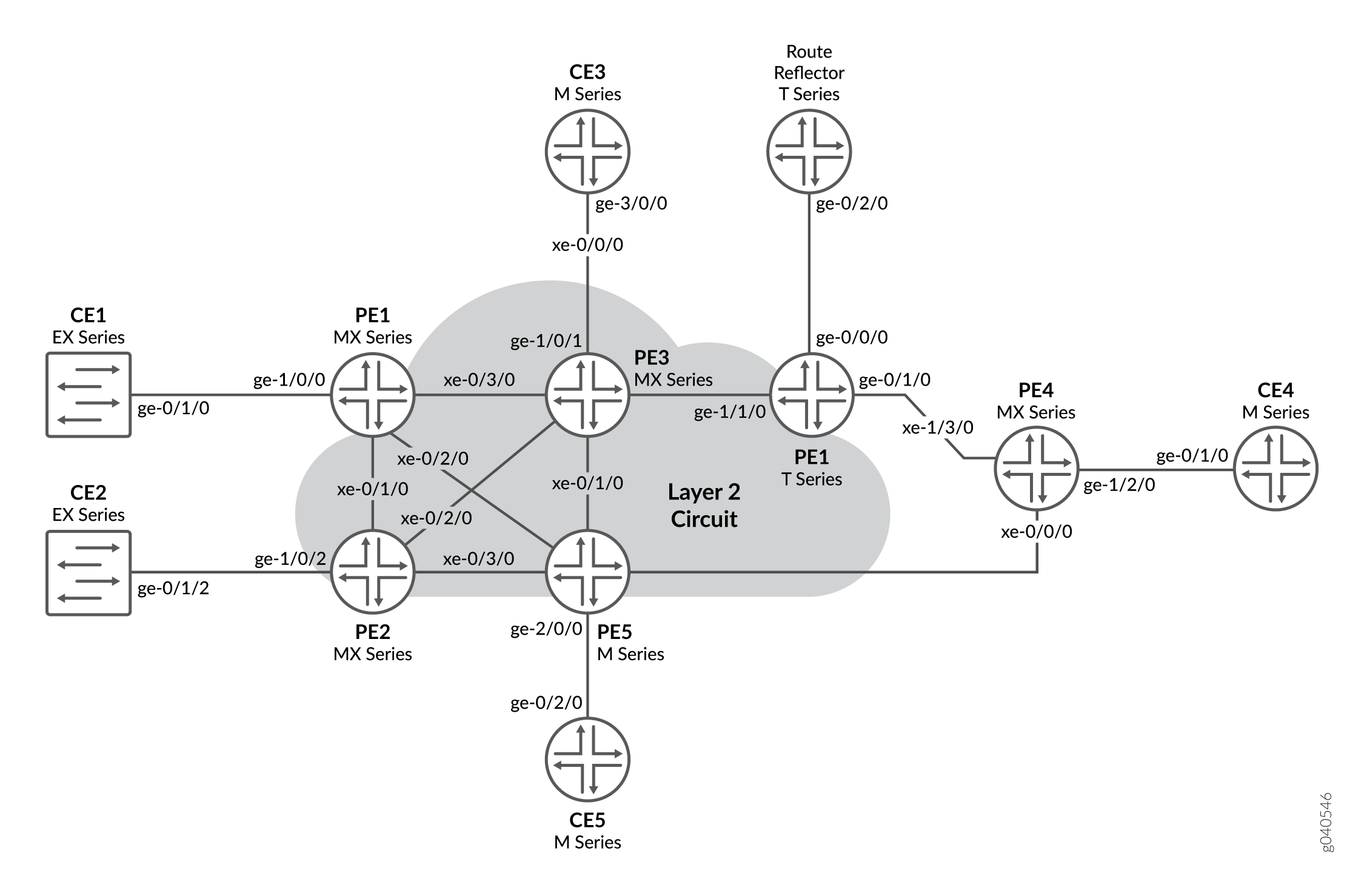
The physical topology of a Layer 2 circuit to Layer 2 circuit interconnection is shown in Figure 1
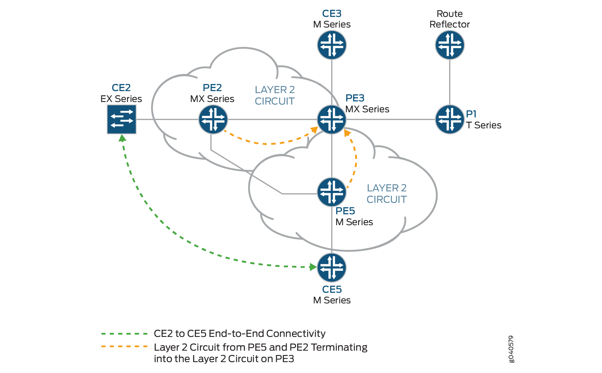
The logical topology of a Layer 2 circuit to Layer 2 circuit interconnection is shown in Figure 2
Topology
Configuration
In any configuration session, it is good practice to verify
periodically that the configuration can be committed using the commit check command.
In this example, the router being configured is identified using the following command prompts:
CE2identifies the customer edge 2 (CE2) routerPE1identifies the provider edge 1 (PE1) routerCE3identifies the customer edge 3 (CE3) routerPE3identifies the provider edge 3 (PE3) routerCE5identifies the customer edge 5 (CE5) routerPE5identifies the provider edge 5 (PE5) router
This example contains the following procedures:
- Configuring PE Router Customer-facing and Loopback Interfaces
- Configuring Core-facing Interfaces
- Configuring Protocols
- Configuring the Layer 2 Circuits
- Interconnecting the Layer 2 Circuits
- Verifying the Layer 2 Circuit to Layer 2 Circuit Interconnection
- Results
Configuring PE Router Customer-facing and Loopback Interfaces
Step-by-Step Procedure
To begin building the interconnection, configure the interfaces on the PE routers. If your network contains provider (P) routers, configure the interfaces on the P routers also. This example shows the configuration for Router PE1 and Router PE5.
On Router PE1, configure the
ge-1/0/0interface encapsulation. To configure the interface encapsulation, include theencapsulationstatement and specify theethernet-cccoption (vlan-ccc encapsulation is also supported). Configure thege-1/0/0.0logical interface family for circuit cross-connect functionality. To configure the logical interface family, include thefamilystatement and specify thecccoption.[edit interfaces] ge-1/0/0 { encapsulation ethernet-ccc; unit 0 { family ccc; } } lo0 { unit 0 { family inet { address 192.0.2.1/24; } } }On Router PE5, configure the
ge-2/0/0interface encapsulation. To configure the interface encapsulation, include theencapsulationstatement and specify theethernet-cccoption. Configure thege-2/0/0.0logical interface family for circuit cross-connect functionality. To configure the logical interface family, include thefamilystatement and specify thecccoption[edit interfaces] ge-2/0/0 { encapsulation ethernet-ccc; unit 0 { family ccc; } } lo0 { unit 0 { family inet { address 192.0.2.5/24; } } }On Router PE3, configure the logical loopback interface. The loopback interface is used to establish the targeted LDP sessions to Routers PE1 and PE5.
[edit interfaces]
lo0 {
    unit 0 {
        family inet {
            address 192.0.2.3/24;
        }
    }
}
Configuring Core-facing Interfaces
Step-by-Step Procedure
This procedure describes how to configure the core-facing
interfaces on the PE routers. This example does not include all the
core-facing interfaces shown in the physical topology illustration.
Enable the mpls and inet address families on
the core-facing interfaces.
On Router PE1, configure the
xe-0/3/0interface. Include thefamilystatement and specify theinetaddress family. Include theaddressstatement and specify10.10.1.1/30as the interface address. Include thefamilystatement and specify themplsaddress family.[edit interfaces] xe-0/3/0 { unit 0 { family inet { address 10.10.1.1/30; } family mpls; } }On Router PE3, configure the core-facing interfaces. Include the
familystatement and specify theinetaddress family. Include theaddressstatement and specify the IPv4 addresses shown in the example as the interface addresses. Include thefamilystatement and specify themplsaddress family. In the example, thexe-0/0/0interface is connected to the route reflector, thexe-0/1/0interface is connected to Router PE5, thexe-0/2/0interface is connected to Router PE2, and thexe-0/3/0interface is connected to Router PE1.[edit interfaces] xe-0/0/0 { unit 0 { family inet { address 10.10.20.2/30; } family mpls; } } xe-0/1/0 { unit 0 { family inet { address 10.10.6.1/30; } family mpls; } } xe-0/2/0 { unit 0 { family inet { address 10.10.5.2/30; } family mpls; } } xe-0/3/0 { unit 0 { family inet { address 10.10.1.2/30; } family mpls; } }On Router PE5, configure the
xe-0/1/0interface. Include thefamilystatement and specify theinetaddress family. Include theaddressstatement and specify10.10.6.2/30as the interface address. Include thefamilystatement and specify themplsaddress family.[edit interfaces] xe-0/1/0 { unit 0 { family inet { address 10.10.6.2/30; } family mpls; } }
Configuring Protocols
Step-by-Step Procedure
This procedure describes how to configure the protocols used in this example. If your network contains P routers, configure the protocols on the P routers also.
Configure all of the PE routers and P routers with OSPF as the
IGP protocol. Enable MPLS and LDP protocols on all of the interfaces
except fxp.0.
On Router PE1, enable OSPF as the IGP. Enable the MPLS and LDP protocols on all interfaces except
fxp.0. LDP is used as the signaling protocol on Router PE1 for the Layer 2 circuit. The following configuration snippet shows the protocol configuration for Router PE1:[edit] protocols { mpls { interface all; interface fxp0.0 { disable; } } ospf { traffic-engineering; area 0.0.0.0 { interface all; interface fxp0.0 { disable; } } } ldp { interface all; interface fxp0.0 { disable; } } }Configure the PE and P routers with OSPF as the IGP. Enable the MPLS and LDP protocols on all interfaces except
fxp.0. The following configuration snippet shows the protocol configuration for Router PE3:[edit] protocols { mpls { interface all; interface fxp0.0 { disable; } } ospf { traffic-engineering; area 0.0.0.0 { interface all; interface fxp0.0 { disable; } } } ldp { interface all; interface fxp0.0 { disable; } } }
Configuring the Layer 2 Circuits
Step-by-Step Procedure
This procedure describes how to configure the Layer 2 circuits.
In this example the ignore-mtu-mismatch statement
is required for the circuit to come up.
On Router PE1, configure the Layer 2 circuit. Include the
l2circuitstatement. Include theneighborstatement and specify the loopback IPv4 address of Router PE3 as the neighbor. Include the interface statement and specifyge-1/0/0.0as the logical interface that is participating in the Layer 2 circuit. Include thevirtual-circuit-idstatement and specify100as the identifier. Include theignore-mtu-mismatchstatement to allow a Layer 2 circuit to be established even though the maximum transmission unit (MTU) configured on the local PE router does not match the MTU configured on the remote PE router.[edit] protocols { l2circuit { neighbor 192.0.2.3 { interface ge-1/0/0.0 { virtual-circuit-id 100; ignore-mtu-mismatch; } } } }On Router PE5, configure the Layer 2 circuit. Include the
l2circuitstatement. Include theneighborstatement and specify the loopback IPv4 address of Router PE3 as the neighbor. Include the interface statement and specifyge-2/0/0.0as the logical interface that is participating in the Layer 2 circuit. Include thevirtual-circuit-idstatement and specify200as the identifier. Include theignore-mtu-mismatchstatement to allow a Layer 2 circuit to be established even though the MTU configured on the local PE router does not match the MTU configured on the remote PE router.[edit] protocols { l2circuit { neighbor 192.0.2.3 { interface ge-2/0/0.0 { virtual-circuit-id 200; ignore-mtu-mismatch; } } } }On Router PE3, configure the Layer 2 circuit to Router PE1. Include the
l2circuitstatement. Include theneighborstatement and specify the loopback IPv4 address of Router PE1 as the neighbor. Include the interface statement and specifyiw0.0as the logical interworking interface that is participating in the Layer 2 circuit. Include thevirtual-circuit-idstatement and specify100as the identifier. Include theignore-mtu-mismatchstatement to allow a Layer 2 circuit to be established even though the MTU configured on the local PE router does not match the MTU configured on the remote PE router.On Router PE3, configure the Layer 2 circuit to Router PE5. Include the
l2circuitstatement. Include theneighborstatement and specify the loopback IPv4 address of Router PE5 as the neighbor. Include the interface statement and specifyiw0.1as the logical interworking interface that is participating in the Layer 2 circuit. Include thevirtual-circuit-idstatement and specify200as the identifier. Include theignore-mtu-mismatchstatement.[edit protocols] l2circuit { neighbor 192.0.2.1 { interface iw0.0 { virtual-circuit-id 100; ignore-mtu-mismatch; } } neighbor 192.0.2.5 { interface iw0.1 { virtual-circuit-id 200; ignore-mtu-mismatch; } } }
Interconnecting the Layer 2 Circuits
Step-by-Step Procedure
Router PE3 is the router that is stitching the Layer 2 circuits together using the interworking interface. The configuration of the peer unit interfaces is what makes the interconnection.
On Router PE3, configure the
iw0.0interface. Include theencapsulationstatement and specify theethernet-cccoption. Include thepeer-unitstatement and specify the logical interface unit1as the peer tunnel interface.On Router PE3, configure the
iw0.1interface. Include theencapsulationstatement and specify theethernet-cccoption. Include thepeer-unitstatement and specify the logical interface unit0as the peer tunnel interface.[edit interfaces] iw0 { unit 0 { encapsulation ethernet-ccc; peer-unit 1; } unit 1 { encapsulation ethernet-ccc; peer-unit 0; } }On Router PE3, configure the Layer 2 interworking
l2iwprotocol. To configure the Layer 2 interworking protocol, include thel2iwstatement at the[edit protocols]hierarchy level.[edit] protocols { l2iw; }On each router, commit the configuration.
user@host> commit check
configuration check succeeds
user@host> commit
Verifying the Layer 2 Circuit to Layer 2 Circuit Interconnection
Step-by-Step Procedure
Verify that the Layer 2 circuit connection on Router PE1 is up, the LDP neighbors are correct, and the MPLS label operations are correct.
On Router PE1, use the
show l2circuit connectionscommand to verify that the Layer 2 circuit from Router PE1 to Router PE3 isUp.user@PE1> show l2circuit connections Layer-2 Circuit Connections: Legend for connection status (St) EI -- encapsulation invalid NP -- interface h/w not present MM -- mtu mismatch Dn -- down EM -- encapsulation mismatch VC-Dn -- Virtual circuit Down CM -- control-word mismatch Up -- operational VM -- vlan id mismatch CF -- Call admission control failure OL -- no outgoing label IB -- TDM incompatible bitrate NC -- intf encaps not CCC/TCC TM -- TDM misconfiguration BK -- Backup Connection ST -- Standby Connection CB -- rcvd cell-bundle size bad XX -- unknown SP -- Static Pseudowire Legend for interface status Up -- operational Dn -- down Neighbor: 192.0.2.3 Interface Type St Time last up # Up trans ge-1/0/0.0(vc 100) rmtUpJan 5 22:00:49 2010 1 Remote PE: 192.0.2.3, Negotiated control-word: Yes (Null) Incoming label: 301328, Outgoing label: 314736 Local interface: ge-1/0/0.0, Status: Up, Encapsulation: ETHERNETOn Router PE1, use the
show ldp neighborcommand to verify that the IPv4 address of Router PE3 is shown as the LDP neighbor.user@PE1> show ldp neighbor Address Interface Label space ID Hold time 192.0.2.3 lo0.0 192.0.2.3:0 41
On Router PE 1, use the
show route table mpls.0command to verify the Layer 2 circuit is using the LDP label to Router PE3 in both directions (Push and Pop). In the example below, the Layer 2 circuit is associated with LDP label301328.user@PE1> show route table mpls.0 mpls.0: 13 destinations, 13 routes (13 active, 0 holddown, 0 hidden) + = Active Route, - = Last Active, * = Both 0 *[MPLS/0] 1w1d 08:25:39, metric 1 Receive 1 *[MPLS/0] 1w1d 08:25:39, metric 1 Receive 2 *[MPLS/0] 1w1d 08:25:39, metric 1 Receive 300432 *[LDP/9] 3d 01:13:57, metric 1 > to 10.10.2.2 via xe-0/1/0.0, Pop 300432(S=0) *[LDP/9] 3d 01:13:57, metric 1 > to 10.10.2.2 via xe-0/1/0.0, Pop 300768 *[LDP/9] 3d 01:13:57, metric 1 > to 10.10.3.2 via xe-0/2/0.0, Pop 300768(S=0) *[LDP/9] 3d 01:13:57, metric 1 > to 10.10.3.2 via xe-0/2/0.0, Pop 300912 *[LDP/9] 3d 01:13:57, metric 1 > to 10.10.3.2 via xe-0/2/0.0, Swap 299856 301264 *[LDP/9] 3d 01:13:53, metric 1 > to 10.10.1.2 via xe-0/3/0.0, Swap 308224 301312 *[LDP/9] 3d 01:13:56, metric 1 > to 10.10.1.2 via xe-0/3/0.0, Pop 301312(S=0) *[LDP/9] 3d 01:13:56, metric 1 > to 10.10.1.2 via xe-0/3/0.0, Pop301328 *[L2CKT/7] 02:33:26 > via ge-1/0/0.0, Pop Offset: 4 ge-1/0/0.0 *[L2CKT/7] 02:33:26, metric2 1 > to 10.10.1.2 via xe-0/3/0.0, Push 314736 Offset: -4On Router PE3, use the
show l2circuit connectionscommand to verify that the Layer 2 circuit from Router PE3 to Router PE5 isUp, that the Layer 2 circuit from Router PE3 to Router PE1 isUp, that the connections to Router PE1 and Router PE5 use the iw0 interface, and that the status for both local iw0 interfaces isUp.user@PE3> show l2circuit connections Layer-2 Circuit Connections: Legend for connection status (St) EI -- encapsulation invalid NP -- interface h/w not present MM -- mtu mismatch Dn -- down EM -- encapsulation mismatch VC-Dn -- Virtual circuit Down CM -- control-word mismatch Up -- operational VM -- vlan id mismatch CF -- Call admission control failure OL -- no outgoing label IB -- TDM incompatible bitrate NC -- intf encaps not CCC/TCC TM -- TDM misconfiguration BK -- Backup Connection ST -- Standby Connection CB -- rcvd cell-bundle size bad XX -- unknown SP -- Static Pseudowire Legend for interface status Up -- operational Dn -- down Neighbor: 192.0.2.1 Interface Type St Time last up # Up trans iw0.0(vc 100) rmt Up Jan 5 13:50:14 2010 1 Remote PE: 192.0.2.1, Negotiated control-word: Yes (Null) Incoming label: 314736, Outgoing label: 301328 Local interface: iw0.0, Status: Up, Encapsulation: ETHERNET Neighbor: 192.0.2.5 Interface Type St Time last up # Up trans iw0.1(vc 200) rmt Up Jan 5 13:49:58 2010 1 Remote PE: 192.0.2.5, Negotiated control-word: Yes (Null) Incoming label: 314752, Outgoing label: 300208 Local interface: iw0.1, Status: Up, Encapsulation: ETHERNETOn Router PE3, use the
show ldp neighborcommand to verify that the correct IPv4 addresses are shown as the LDP neighbor.user@PE3> show ldp neighbor Address Interface Label space ID Hold time 192.0.2.1 lo0.0 192.0.2.1:0 44 192.0.2.2 lo0.0 192.0.2.2:0 42 192.0.2.4 lo0.0 192.0.2.4:0 31 192.0.2.5 lo0.0 192.0.2.5:0 44
On Router PE3, use the
show route table mpls.0command to verify that thempls.0routing table is populated with the Layer 2 interworking routes. Notice that in this example, the router is swapping label314736received from Router PE1 on theiw0.0to label301328.user@PE3> show route table mpls.0 mpls.0: 16 destinations, 18 routes (16 active, 2 holddown, 0 hidden) + = Active Route, - = Last Active, * = Both 0 *[MPLS/0] 1w1d 08:28:24, metric 1 Receive 1 *[MPLS/0] 1w1d 08:28:24, metric 1 Receive 2 *[MPLS/0] 1w1d 08:28:24, metric 1 Receive 308160 *[LDP/9] 3d 01:16:55, metric 1 > to 10.10.1.1 via xe-0/3/0.0, Pop 308160(S=0) *[LDP/9] 3d 01:16:55, metric 1 > to 10.10.1.1 via xe-0/3/0.0, Pop 308176 *[LDP/9] 3d 01:16:54, metric 1 > to 10.10.6.2 via xe-0/1/0.0, Pop 308176(S=0) *[LDP/9] 3d 01:16:54, metric 1 > to 10.10.6.2 via xe-0/1/0.0, Pop 308192 *[LDP/9] 00:21:40, metric 1 > to 10.10.20.1 via xe-0/0/0.0, Swap 601649 to 10.10.6.2 via xe-0/1/0.0, Swap 299856 308208 *[LDP/9] 3d 01:16:54, metric 1 > to 10.10.5.1 via xe-0/2/0.0, Pop 308208(S=0) *[LDP/9] 3d 01:16:54, metric 1 > to 10.10.5.1 via xe-0/2/0.0, Pop 308224 *[LDP/9] 3d 01:16:52, metric 1 > to 10.10.20.1 via xe-0/0/0.0, Pop 308224(S=0) *[LDP/9] 3d 01:16:52, metric 1 > to 10.10.20.1 via xe-0/0/0.0, Pop 314736 *[L2IW/6] 02:35:31, metric2 1 > to 10.10.6.2 via xe-0/1/0.0, Swap 300208 [L2CKT/7] 02:35:31 > via iw0.0, Pop Offset: 4 314752 *[L2IW/6] 02:35:31, metric2 1 > to 10.10.1.1 via xe-0/3/0.0, Swap 301328 [L2CKT/7] 02:35:47 > via iw0.1, Pop Offset: 4 iw0.0 *[L2CKT/7] 02:35:31, metric2 1 > to 10.10.1.1 via xe-0/3/0.0, Push 301328 Offset: -4 iw0.1 *[L2CKT/7] 02:35:47, metric2 1 > to 10.10.6.2 via xe-0/1/0.0, Push 300208 Offset: -4Verify that Router CE1 can send traffic to and receive traffic from Router CE5 across the interconnection, using the
pingcommand.user@CE1>
ping 198.51.100.11PING 198.51.100.11 (198.51.100.11): 56 data bytes 64 bytes from 198.51.100.11: icmp_seq=1 ttl=64 time=22.425 ms 64 bytes from 198.51.100.11: icmp_seq=2 ttl=64 time=1.299 ms 64 bytes from 198.51.100.11: icmp_seq=3 ttl=64 time=1.032 ms 64 bytes from 198.51.100.11: icmp_seq=4 ttl=64 time=1.029 msVerify that Router CE5 can send traffic to and receive traffic from Router CE1 across the interconnection, using the
pingcommand.user@CE5>
ping 198.51.100.1PING 198.51.100.1 (198.51.100.1): 56 data bytes 64 bytes from 198.51.100.1: icmp_seq=0 ttl=64 time=1.077 ms 64 bytes from 198.51.100.1: icmp_seq=1 ttl=64 time=0.957 ms 64 bytes from 198.51.100.1: icmp_seq=2 ttl=64 time=1.057 ms 1.017 ms
Results
The configuration and verification of this example has been completed. The following section is for your reference.
The relevant sample configuration for Router PE1 follows.
Router PE1
[edit]
interfaces {
    xe-0/1/0 {
        unit 0 {
            family inet {
                address 10.10.2.1/30;
            }
            family mpls;
        }
    }
    xe-0/2/0 {
        unit 0 {
            family inet {
                address 10.10.3..1/30;
            }
            family mpls;
        }
    }
    xe-0/3/0 {
        unit 0 {
            family inet {
                address 10.10.1.1/30;
            }
            family mpls;
        }
    }
    ge-1/0/0 {
        encapsulation ethernet-ccc;
        unit 0 {
            family ccc;
        }
    }
    lo0 {
        unit 0 {
            family inet {
                address 192.0.2.1/24;
            }
        }
    }
}
forwarding-options {
    hash-key {
        family inet {
            layer-3;
            layer-4;
        }
        family mpls {
            label-1;
            label-2;
        }
    }
}
routing-options {
    static {
        route 172.16.0.0/8 next-hop 172.19.59.1;
    }
    autonomous-system 65000;
}
protocols {
    mpls {
        interface all;
        interface fxp0.0 {
            disable;
        }
    }
    ospf {
        traffic-engineering;
        area 0.0.0.0 {
            interface all;
            interface fxp0.0 {
                disable;
            }
        }
    }
    ldp {
        interface all;
        interface fxp0.0 {
            disable;
        }
    }
    l2circuit {
        neighbor 192.0.2.3 {
            interface ge-1/0/0.0 {
                virtual-circuit-id 100;
                ignore-mtu-mismatch;
            }
        }
    }
}
The relevant sample configuration for Router PE3 follows.
Router PE3
[edit]
interfaces {
    xe-0/0/0 {
        unit 0 {
            family inet {
                address 10.10.20.2/30;
            }
            family mpls;
        }
    }
    xe-0/1/0 {
        unit 0 {
            family inet {
                address 10.10.6.1/30;
            }
            family mpls;
        }
    }
    xe-0/2/0 {
        unit 0 {
            family inet {
                address 10.10.5.2/30;
            }
            family mpls;
        }
    }
    xe-0/3/0 {
        unit 0 {
            family inet {
                address 10.10.1.2/30;
            }
            family mpls;
        }
    }
    ge-1/0/1 {
        encapsulation ethernet-ccc;
        unit 0 {
            family ccc;
        }
    }
    iw0 {
        unit 0 {
            encapsulation ethernet-ccc;
            peer-unit 1;
        }
        unit 1 {
            encapsulation ethernet-ccc;
            peer-unit 0;
        }
    }
    lo0 {
        unit 0 {
            family inet {
                address 192.0.2.3/24;
            }
        }
    }
}
routing-options {
    static {
        route 172.16.0.0/8 next-hop 172.19.59.1;
    }
    autonomous-system 65000;
}
protocols {
    l2iw;
    mpls {
        interface all;
        interface fxp0.0 {
            disable;
        }
    }
    ospf {
        area 0.0.0.0 {
            interface all;
            interface fxp0.0 {
                disable;
            }
        }
    }
    ldp {
        interface all;
        interface fxp0.0 {
            disable;
        }
    }
    l2circuit {
        neighbor 192.0.2.1 {
            interface iw0.0 {
                virtual-circuit-id 100;
                ignore-mtu-mismatch;
            }
        }
        neighbor 192.0.2.5 {
            interface iw0.1 {
                virtual-circuit-id 200;
                ignore-mtu-mismatch;
            }
        }
    }
}