Example: Configuring a Multisegment Pseudowire
This example shows how to configure a dynamic multisegment pseudowire (MS-PW), where the stitching provider edge (S-PE) devices are automatically and dynamically discovered by BGP, and pseudowires are signaled by LDP using FEC 129. This arrangement requires minimum provisioning on the S-PEs, thereby reducing the configuration burden that is associated with statically configured Layer 2 circuits while still using LDP as the underlying signaling protocol.
Requirements
This example uses the following hardware and software components:
Six routers that can be a combination of M Series Multiservice Edge Routers, MX Series 5G Universal Routing Platforms, T Series Core Routers, or PTX Series Packet Transport Routers.
Two remote PE devices configured as terminating PEs (T-PEs).
Two S-PEs configured as:
Route reflectors, in the case of interarea configuration.
AS boundary routers or route reflectors, in the case of inter-AS configuration.
Junos OS Release 13.3 or later running on all the devices.
Before you begin:
Configure the device interfaces.
Configure OSPF or any other IGP protocol.
Configure BGP.
Configure LDP.
Configure MPLS.
Overview
Starting with Junos OS Release 13.3, you can configure an MS-PW using FEC 129 with LDP signaling and BGP autodiscovery in an MPLS packet-switched network (PSN). The MS-PW feature also provides operation, administration, and management (OAM) capabilities, such as ping, traceroute, and BFD, from the T-PE devices.
To enable autodiscovery of S-PEs in an MS-PW, include the auto-discovery-mspw statement at the [edit protocols bgp
group group-name family l2vpn] hierarchy
level.
family l2vpn {
    auto-discovery-mspw;
}
The automatic selection of S-PE and dynamic setting up of an
MS-PW rely heavily on BGP. BGP network layer reachability information
(NLRI) constructed for the FEC 129 pseudowire to autodiscover the
S-PE is called an MS-PW NLRI [draft-ietf-pwe3-dynamic-ms-pw-15.txt].
The MS-PW NLRI is essentially a prefix consisting of a route distinguisher
(RD) and FEC 129 source attachment identifier (SAII). It is referred
to as a BGP autodiscovery (BGP-AD) route and is encoded as RD:SAII.
Only T-PEs that are provisioned with type 2 AIIs initiate their own MS-PW NLRI respectively. Since a type 2 AII is globally unique, an MS-PW NLRI is used to identify a PE device to which the type 2 AII is provisioned. The difference between a type 1 AII and a type 2 AII requires that a new address family indicator (AFI) and subsequent address family identifier (SAFI) be defined in BGP to support an MS-PW. The proposed AFI and SAFI value pair used to identify the MS-PW NLRI is 25 and 6, respectively (pending IANA allocation).
The AFI and SAFI values support autodiscovery of S-PEs and should be configured on both T-PEs that originate the routes, and the S-PEs that participate in the signaling.
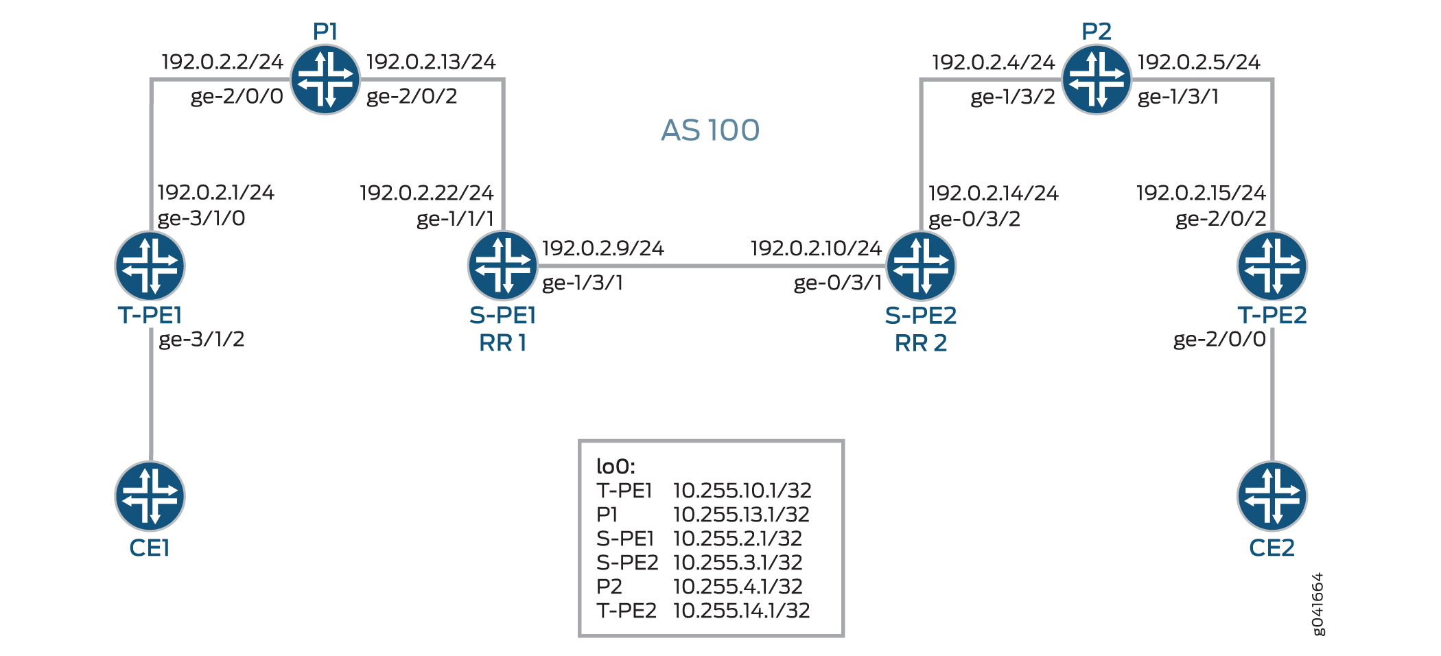
Figure 1 illustrates an inter-area MS-PW setup between two remote PE routers—T-PE1 and T-PE2. The Provider (P) routers are P1 and P2, and the S-PE routers are S-PE1 and S-PE2. The MS-PW is established between T-PE1 and T-PE2, and all the devices belong to the same AS—AS 100. Since S-PE1 and S-PE2 belong to the same AS, they act as route reflectors and are also known as RR 1 and RR 2, respectively.
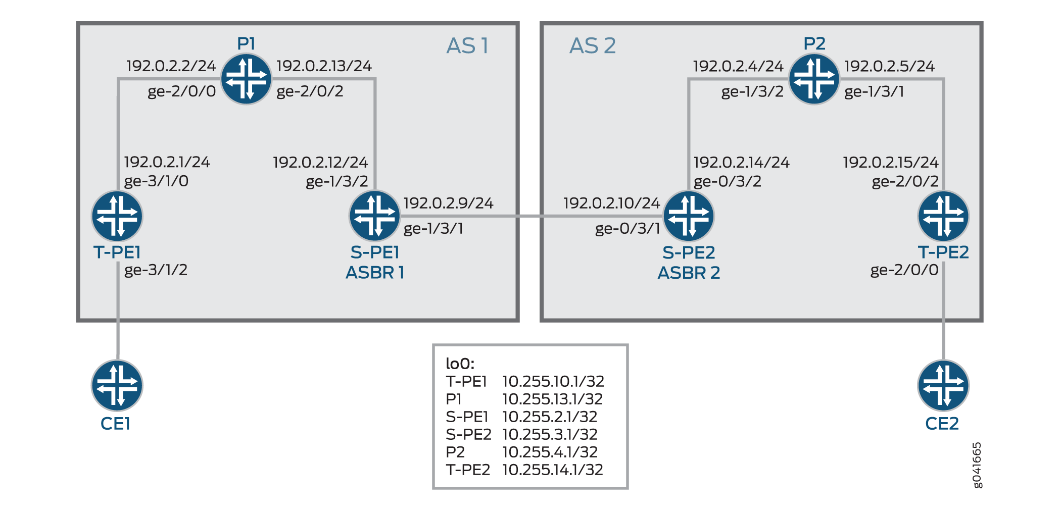
Figure 2 illustrates an inter-AS MS-PW setup. The MS-PW is established between T-PE1 and T-PE2, where T-PE1, P1, and S-PE1 belong to AS 1, and S-PE2, P2, and T-PE2 belong to AS 2. Since S-PE1 and S-PE2 belong to different ASs, they are configured as ASBR routers and are also known as ASBR 1 and ASBR 2, respectively.
The following sections provide information about how an MS-PW is established in an interarea and inter-AS scenario.
Minimum Configuration Requirements on S-PE
In order to dynamically discover both ends of an SS-PW and set up a T-LDP session dynamically, the following is required:
For interarea MS-PW, each S-PE plays both an ABR and BGP route reflector role.
In the interarea case, as seen in Figure 1, the S-PE plays a BGP route reflector role and reflects the BGP-AD route to its client. A BGP-AD route advertised by one T-PE eventually reaches its remote T-PE. Because of the next-hop-self set by each S-PE, the S-PE or T-PE that receives a BGP-AD route can always discover the S-PE that advertises the BGP-AD in its local AS or local area through the BGP next hop.
For inter-AS MS-PW, each S-PE plays either an ASBR or a BGP route reflector role.
In an MS-PW, the two T-PEs initiate a BGP-AD route respectively. When the S-PE receives the BGP-AD route through either the IBGP session with the T-PE or through a regular BGP-RR, it sets the next-hop-self before re-advertising the BGP-AD route to one or more of its EBGP peers in the inter-AS case, as seen in Figure 2.
Each S-PE must set next-hop-self when re-advertising or reflecting a BGP-AD route for the MS-PW.
Active and Passive Role of T-PE
To ensure that the same set of S-PEs are being used for a MS-PW in both directions, the two T-PEs play different roles in terms of FEC 129 signaling. This is to avoid different paths being chosen by T-PE1 and T-PE2 when each S-PE is dynamically selected for an MS-PW.
When an MS-PW is signaled using FEC 129, each T-PE might independently start signaling the MS-PW. The signaling procedure can result in an attempt to set up each direction of the MS-PW through different S-PEs.
To avoid this situation, one of the T-PEs must start the pseudowire signaling (active role), while the other waits to receive the LDP label mapping before sending the respective pseudowire LDP label mapping message (passive role). When the MS-PW path is dynamically placed, the active T-PE (the Source T-PE) and the passive T-PE (the Target T-PE) must be identified before signaling is initiated for a given MS-PW. The determination of which T-PE assumes the active role is done based on the SAII value, where the T-PE that has a larger SAII value plays the active role.
In this example, the SAII values of T-PE1 and T-PE 2 are 800:800:800 and 700:700:700, respectively. Since
T-PE1 has a higher SAII value, it assumes the active role and T-PE2
assumes the passive role.
Directions for Establishing an MS-PW
The directions used by the S-PE for setting up the MS-PW are:
Forwarding direction—From an active T-PE to a passive T-PE.
In this direction, the S-PEs perform a BGP-AD route lookup to determine the next-hop S-PE to send the label mapping message.
Reverse direction—From a passive T-PE to an active T-PE.
In this direction, the S-PEs do not perform a BGP-AD route lookup, because the label mapping messages are received from the T-PEs, and the stitching routes are installed in the S-PEs.
In this example, the MS-PW is established in the forwarding direction from T-PE1 to T-PE2. When the MS-PW is placed from T-PE2 to T-PE1, the MS-PW is established in the reverse direction.
Autodiscovery and Dynamic Selection of S-PE
A new AFI and SAFI value is defined in BGP to support the MS-PWs based on type 2 AII. This new address family supports autodiscovery of S-PEs. This address family must be configured on both the TPEs and SPEs.
It is the responsibility of the Layer 2 VPN component to dynamically select the next S-PE to use along the MS-PW in the forwarding direction.
In the forwarding direction, the selection of the next S-PE is based on the BGP-AD route advertised by the BGP and pseudowire FEC information sent by the LDP. The BGP-AD route is initiated by the passive T-PE (T-PE2) in the reverse direction while the pseudowire FEC information is sent by LDP from the active T-PE (T-PE1) in the forwarding direction.
In the reverse direction, the next S-PE (S-PE2) or the active T-PE (T-PE1) is obtained by looking up the S-PE (S-PE1) that it used to set up the pseudowire in the forwarding direction.
Provisioning a T-PE
To support FEC 129 type 2 AII, the T-PE needs to configure its remote T-PE's IP address, a global ID, and an attachment circuit ID. Explicit paths where a set of S-PEs to use is explicitly specified on a T-PE is not supported. This eliminates the need to provision each S-PE with a type 2 AII.
Stitching an MS-PW
An S-PE performs the following MPLS label operations before forwarding the received label mapping message to the next S-PE:
Pops the MPLS tunnel label.
Pops the VC label.
Pushes a new VC label.
Pushes an MPLS tunnel label used for the next segment.
Establishing an MS-PW
After completing the necessary configuration, an MS-PW is established in the following manner:
The SAII values are exchanged between T-PE1 and T-PE2 using BGP.
T-PE1 assumes the active T-PE role, because it is configured with a higher SAII value. T-PE2 becomes the passive T-PE.
T-PE1 receives the BGP-AD route originated by T-PE2. It compares the AII values obtained from T-PE2 in the received BGP-AD route against the AII values provisioned locally.
If the AII values match, T-PE1 performs a BGP-AD route lookup to elect the first S-PE (S-PE1).
T-PE1 sends an LDP label mapping message to S-PE1.
Using the BGP-AD route originated from T-PE2, and the LDP label mapping message received from T-PE1, S-PE1 selects the next S-PE (S-PE2) in the forwarding direction.
To do this, S-PE1 compares SAII obtained from the BGP-AD route against the TAI from the LDP label mapping message.
If the AII values match, S-PE1 finds S-PE2 through the BGP next hop associated with the BGP-AD route.
The process of selecting S-PE goes on until the last S-PE establishes a T-LDP session with T-PE2. When T-PE2 receives the LDP label mapping message from the last S-PE (S-PE2), it initiates its own label mapping message and sends it back to S-PE2.
When all the label mapping messages are received on S-PE1 and S-PE2, the S-PEs install the stitching routes. Thus, when the MS-PW is established in the reverse direction, the S-PEs need not perform BGP-AD route lookup to determine its next hop as it did in the forwarding direction.
OAM Support for an MS-PW
After the MS-PW is established, the following OAM capabilities can be executed from the T-PE devices:
Ping
End-to-End Connectivity Verification Between T-PEs
If T-PE1, S-PEs, and T-PE2 support Control Word (CW), the pseudowire control plane automatically negotiates the use of the CW. Virtual Circuit Connectivity Verification (VCCV) Control Channel (CC) Type 3 will function correctly whether or not the CW is enabled on the pseudowire. However, VCCV Type 1, which is used for end-to-end verification only, is only supported if the CW is enabled.
The following is a sample:
Ping from T-P1 to T-PE2
user@T-PE1> ping mpls l2vpn fec129 instance instance-name local-id SAII of T-PE1 remote-pe-address address of T-PE2 remote-id TAII of T-PE2
or
user@T-PE1> ping mpls l2vpn fec129 interface CE1-facing interface
Partial Connectivity Verification from T-PE to Any S-PE
To trace part of an MS-PW, the TTL of the pseudowire label can be used to force the VCCV message to pop out at an intermediate node. When the TTL expires, the S-PE can determine that the packet is a VCCV packet either by checking the CW or by checking for a valid IP header with UDP destination port 3502 (if the CW is not in use). The packet should then be diverted to VCCV processing.
If T-PE1 sends a VCCV message with the TTL of the pseudowire label equal to 1, the TTL expires at the S-PE. T-PE1 can thus verify the first segment of the pseudowire.
The VCCV packet is built according to RFC 4379. All the information necessary to build the VCCV LSP ping packet is collected by inspecting the S-PE TLVs. This use of the TTL is subject to the caution expressed in RFC 5085. If a penultimate LSR between S-PEs or between an S-PE and a T-PE manipulates the pseudowire label TTL, the VCCV message might not emerge from the MS-PW at the correct S-PE.
The following is a sample:
Ping from T-PE1 to S-PE
user@T-PE1> ping mpls l2vpn fec129 interface CE1-facing interface bottom-label-ttl segment
The
bottom-label-ttlvalue is 1 for S-PE1 and 2 for S-PE2.The
bottom-label-ttlstatement sets the correct VC label TTL, so the packets are popped to the correct SS-PW for VCCV processing.
Note:Junos OS supports VCCV Type 1 and Type 3 for the MS-PW OAM capability. VCCV Type 2 is not supported.
Traceroute
Traceroute tests each S-PE along the path of the MS-PW in a single operation similar to LSP trace. This operation is able to determine the actual data path of the MS-PW, and is used for dynamically signaled MS-PWs.
user@T-PE1> traceroute mpls l2vpn fec129 interface CE1-facing interface
Bidirectional Forwarding Detection
Bidirectional Forwarding Detection (BFD) is a detection protocol designed to provide fast forwarding path failure detection times for all media types, encapsulations, topologies, and routing protocols. In addition to fast forwarding path failure detection, BFD provides a consistent failure detection method for network administrators. The router or switch can be configured to log a system log (syslog) message when BFD goes down.
user@T-PE1> show bfd session extensive
Configuration
Configuring an Interarea MS-PW
CLI Quick Configuration
To quickly configure this example, copy the
following commands, paste them into a text file, remove any line breaks,
change any details necessary to match your network configuration,
and then copy and paste the commands into the CLI at the [edit] hierarchy level.
T-PE1
set interfaces ge-3/1/0 unit 0 family inet address 192.0.2.1/24
set interfaces ge-3/1/0 unit 0 family mpls
set interfaces ge-3/1/2 encapsulation ethernet-ccc
set interfaces ge-3/1/2 unit 0
set interfaces lo0 unit 0 family inet address 10.255.10.1/32 primary
set routing-options autonomous-system 100
set protocols mpls interface all
set protocols mpls interface fxp0.0 disable
set protocols bgp family l2vpn auto-discovery-mspw
set protocols bgp group mspw type internal
set protocols bgp group mspw local-address 10.255.10.1
set protocols bgp group mspw neighbor 10.255.2.1
set protocols ospf area 0.0.0.0 interface lo0.0
set protocols ospf area 0.0.0.0 interface all
set protocols ospf area 0.0.0.0 interface fxp0.0 disable
set protocols ldp interface all
set protocols ldp interface fxp0.0 disable
set protocols ldp interface lo0.0
set routing-instances ms-pw instance-type l2vpn
set routing-instances ms-pw interface ge-3/1/2.0
set routing-instances ms-pw route-distinguisher 10.10.10.10:15
set routing-instances ms-pw l2vpn-id l2vpn-id:100:15
set routing-instances ms-pw vrf-target target:100:115
set routing-instances ms-pw protocols l2vpn site CE1 source-attachment-identifier 800:800:800
set routing-instances ms-pw protocols l2vpn site CE1 interface ge-3/1/2.0 target-attachment-identifier 700:700:700
set routing-instances ms-pw protocols l2vpn pseudowire-status-tlv
set routing-instances ms-pw protocols l2vpn oam bfd-liveness-detection minimum-interval 300
P1
set interfaces ge-2/0/0 unit 0 family inet address 192.0.2.2/24
set interfaces ge-2/0/0 unit 0 family mpls
set interfaces ge-2/0/2 unit 0 family inet address 192.0.2.13/24
set interfaces ge-2/0/2 unit 0 family mpls
set interfaces lo0 unit 0 family inet address 10.255.13.1/32 primary
set routing-options autonomous-system 100
set protocols mpls interface all
set protocols mpls interface fxp0.0 disable
set protocols ospf area 0.0.0.0 interface lo0.0
set protocols ospf area 0.0.0.0 interface all
set protocols ospf area 0.0.0.0 interface fxp0.0 disable
set protocols ldp interface all
set protocols ldp interface fxp0.0 disable
set protocols ldp interface lo0.0
S-PE1 (RR 1)
set interfaces ge-1/3/1 unit 0 family inet address 192.0.2.9/24
set interfaces ge-1/3/1 unit 0 family mpls
set interfaces ge-1/3/2 unit 0 family inet address 192.0.2.22/24
set interfaces ge-1/3/2 unit 0 family mpls
set interfaces lo0 unit 0 family inet address 10.255.2.1/32 primary
set routing-options autonomous-system 100
set protocols mpls interface all
set protocols mpls interface fxp0.0 disable
set protocols bgp family l2vpn auto-discovery-mspw
set protocols bgp group mspw type internal
set protocols bgp group mspw local-address 10.255.2.1
set protocols bgp group mspw export next-hop-self
set protocols bgp group mspw cluster 203.0.113.0
set protocols bgp group mspw neighbor 10.255.10.1
set protocols bgp group mspw neighbor 10.255.3.1
set protocols ospf area 0.0.0.0 interface lo0.0
set protocols ospf area 0.0.0.0 interface all
set protocols ospf area 0.0.0.0 interface fxp0.0 disable
set protocols ldp interface all
set protocols ldp interface fxp0.0 disable
set protocols ldp interface lo0.0
set policy-options policy-statement next-hop-self then next-hop self
set policy-options policy-statement send-inet0 from protocol bgp
set policy-options policy-statement send-inet0 then accept
S-PE2 (RR 2)
set interfaces ge-0/3/1 unit 0 family inet address 192.0.2.10/24
set interfaces ge-0/3/1 unit 0 family mpls
set interfaces ge-0/3/2 unit 0 family inet address 192.0.2.14/24
set interfaces ge-0/3/2 unit 0 family mpls
set interfaces lo0 unit 0 family inet address 10.255.3.1/32 primary
set protocols mpls interface all
set protocols mpls interface fxp0.0 disable
set protocols bgp family l2vpn auto-discovery-mspw
set protocols bgp group mspw type internal
set protocols bgp group mspw local-address 10.255.3.1
set protocols bgp group mspw export next-hop-self
set protocols bgp group mspw cluster 198.51.100.0
set protocols bgp group mspw neighbor 10.255.2.1
set protocols bgp group mspw neighbor 10.255.14.1
set protocols bgp group int type internal
set protocols bgp group int local-address 10.255.3.1
set protocols bgp group int neighbor 10.255.2.1
set protocols ospf area 0.0.0.0 interface all
set protocols ospf area 0.0.0.0 interface lo0.0
set protocols ospf area 0.0.0.0 interface fxp0.0 disable
set protocols ldp interface all
set protocols ldp interface fxp0.0 disable
set protocols ldp interface lo0.0
set policy-options policy-statement next-hop-self then next-hop self
set policy-options policy-statement send-inet0 from protocol bgp
set policy-options policy-statement send-inet0 then accept
P2
set interfaces ge-1/3/1 unit 0 family inet address 192.0.2.5/24
set interfaces ge-1/3/1 unit 0 family mpls
set interfaces ge-1/3/2 unit 0 family inet address 192.0.2.4/24
set interfaces ge-1/3/2 unit 0 family mpls
set interfaces lo0 unit 0 family inet address 10.255.4.1/32 primary
set routing-options autonomous-system 100
set protocols mpls interface all
set protocols mpls interface fxp0.0 disable
set protocols ospf area 0.0.0.0 interface all
set protocols ospf area 0.0.0.0 interface lo0.0
set protocols ospf area 0.0.0.0 interface fxp0.0 disable
set protocols ldp interface all
set protocols ldp interface fxp0.0 disable
set protocols ldp interface lo0.0
T-PE2
set interfaces ge-2/0/0 encapsulation ethernet-ccc
set interfaces ge-2/0/0 unit 0
set interfaces ge-2/0/2 unit 0 family inet address 192.0.2.15/24
set interfaces ge-2/0/2 unit 0 family mpls
set interfaces lo0 unit 0 family inet address 10.255.14.1/32 primary
set routing-options autonomous-system 100
set protocols mpls interface all
set protocols mpls interface fxp0.0 disable
set protocols bgp family l2vpn auto-discovery-mspw
set protocols bgp group mspw type internal
set protocols bgp group mspw local-address 10.255.14.1
set protocols bgp group mspw neighbor 10.255.3.1
set protocols ospf area 0.0.0.0 interface all
set protocols ospf area 0.0.0.0 interface fxp0.0 disable
set protocols ospf area 0.0.0.0 interface lo0.0 passive
set protocols ldp interface all
set protocols ldp interface fxp0.0 disable
set protocols ldp interface lo0.0
set routing-instances ms-pw instance-type l2vpn
set routing-instances ms-pw interface ge-2/0/0.0
set routing-instances ms-pw route-distinguisher 10.10.10.10:15
set routing-instances ms-pw l2vpn-id l2vpn-id:100:15
set routing-instances ms-pw vrf-target target:100:115
set routing-instances ms-pw protocols l2vpn site CE2 source-attachment-identifier 700:700:700
set routing-instances ms-pw protocols l2vpn site CE2 interface ge-2/0/0.0 target-attachment-identifier 800:800:800
set routing-instances ms-pw protocols l2vpn pseudowire-status-tlv
set routing-instances ms-pw protocols l2vpn oam bfd-liveness-detection minimum-interval 300
Step-by-Step Procedure
The following example requires you to navigate various levels in the configuration hierarchy. For information about navigating the CLI, see Using the CLI Editor in Configuration Mode.
To configure T-PE1 in the interarea scenario:
Repeat this procedure for the T-PE2 device in the MPLS domain, after modifying the appropriate interface names, addresses, and other parameters.
Configure the T-PE1 interfaces.
[edit interfaces]user@T-PE1# set ge-3/1/0 unit 0 family inet address 192.0.2.1/24 user@T-PE1# set ge-3/1/0 unit 0 family mpls user@T-PE1# set ge-3/1/2 encapsulation ethernet-ccc user@T-PE1# set ge-3/1/2 unit 0 user@T-PE1# set lo0 unit 0 family inet address 10.255.10.1/32 primarySet the autonomous system number.
[edit routing-options]user@T-PE1# set autonomous-system 100Enable MPLS on all the interfaces of T-PE1, excluding the management interface.
[edit protocols]user@T-PE1# set mpls interface all user@T-PE1# set mpls interface fxp0.0 disableEnable autodiscovery of intermediate S-PEs that make up the MS-PW using BGP.
[edit protocols]user@T-PE1# set bgp family l2vpn auto-discovery-mspwConfigure the BGP group for T-PE1.
[edit protocols]user@T-PE1# set bgp group mspw type internalAssign local and neighbor addresses to the mspw group for T-PE1 to peer with S-PE1.
[edit protocols]user@T-PE1# set bgp group mspw local-address 10.255.10.1 user@T-PE1# set bgp group mspw neighbor 10.255.2.1Configure OSPF on all the interfaces of T-PE1, excluding the management interface.
[edit protocols]
user@T-PE1# set ospf area 0.0.0.0 interface lo0.0
user@T-PE1# set ospf area 0.0.0.0 interface all
user@T-PE1# set ospf area 0.0.0.0 interface fxp0.0 disable
Configure LDP on all the interfaces of T-PE1, excluding the management interface.
[edit protocols]
user@T-PE1# set ldp interface all
user@T-PE1# set ldp interface fxp0.0 disable
user@T-PE1# set ldp interface lo0.0
Configure the Layer 2 VPN routing instance on T-PE1.
[edit routing-instances]
user@T-PE1# set ms-pw instance-type l2vpn
Assign the interface name for the mspw routing instance.
[edit routing-instances]
user@T-PE1# set ms-pw interface ge-3/1/2.0
Configure the route distinguisher for the mspw routing instance.
[edit routing-instances]
user@T-PE1# set ms-pw route-distinguisher 10.10.10.10:15
Configure the Layer 2 VPN ID community for FEC 129 MS-PW.
[edit routing-instances]
user@T-PE1# set ms-pw l2vpn-id l2vpn-id:100:15
Configure a VPN routing and forwarding (VRF) target for the mspw routing instance.
[edit routing-instances]
user@T-PE1# set ms-pw vrf-target target:100:115
Configure the source attachment identifier (SAI) value using Layer 2 VPN as the routing protocol for the mspw routing instance.
[edit routing-instances]
user@T-PE1# set ms-pw protocols l2vpn site CE1 source-attachment-identifier 800:800:800
Assign the interface name that connects the CE1 site to the VPN, and configure the target attachment identifier (TAI) value using Layer 2 VPN as the routing protocol for the mspw routing instance.
[edit routing-instances]
user@T-PE1# set ms-pw protocols l2vpn site CE1 interface ge-3/1/2.0 target-attachment-identifier 700:700:700
(Optional) Configure T-PE1 to send MS-PW status TLVs.
[edit routing-instances]
user@T-PE1# set ms-pw protocols l2vpn pseudowire-status-tlv
(Optional) Configure OAM capabilities for the VPN.
[edit routing-instances]
user@T-PE1# set ms-pw protocols l2vpn oam bfd-liveness-detection minimum-interval 300
Step-by-Step Procedure
The following example requires you to navigate various levels in the configuration hierarchy. For information about navigating the CLI, see Using the CLI Editor in Configuration Mode.
To configure S-PE1 (RR 1) in the interarea scenario:
Repeat this procedure for the S-PE2 (RR 2) device in the MPLS domain, after modifying the appropriate interface names, addresses, and other parameters.
Configure the S-PE1 interfaces.
[edit interfaces]user@S-PE1# set ge-1/3/1 unit 0 family inet address 192.0.2.9/24 user@S-PE1# set ge-1/3/1 unit 0 family mpls user@S-PE1# set ge-1/3/2 unit 0 family inet address 192.0.2.22/24 user@S-PE1# set ge-1/3/2 unit 0 family mpls user@S-PE1# set lo0 unit 0 family inet address 10.255.2.1/32 primarySet the autonomous system number.
[edit routing-options]user@S-PE1# set autonomous-system 100Enable MPLS on all the interfaces of T-PE1, excluding the management interface.
[edit protocols]user@S-PE1# set mpls interface all user@S-PE1# set mpls interface fxp0.0 disableEnable autodiscovery of S-PE using BGP.
[edit protocols]user@S-PE1# set bgp family l2vpn auto-discovery-mspwConfigure the BGP group for S-PE1.
[edit protocols]user@S-PE1# set bgp group mspw type internalConfigure S-PE1 to act as a route reflector.
[edit protocols]user@S-PE1# set bgp group mspw export next-hop-self user@S-PE1# set bgp group mspw cluster 203.0.113.0Assign local and neighbor addresses to the mspw group for S-PE1 to peer with T-PE1 and S-PE2.
[edit protocols]user@S-PE1# set bgp group mspw local-address 10.255.2.1 user@S-PE1# set bgp group mspw neighbor 10.255.10.1 (to T-PE1) user@S-PE1# set bgp group mspw neighbor 10.255.3.1 (to S-PE2)Configure OSPF on all the interfaces of S-PE1, excluding the management interface.
[edit protocols]
user@S-PE1# set ospf area 0.0.0.0 interface all
user@S-PE1# set ospf area 0.0.0.0 interface fxp0.0 disable
user@S-PE1# set ospf area 0.0.0.0 interface lo0.0
Configure LDP on all the interfaces of S-PE1, excluding the management interface.
[edit protocols]
user@S-PE1# set ldp interface all
user@S-PE1# set ldp interface fxp0.0 disable
user@S-PE1# set ldp interface lo0.0
Define the policy for enabling next-hop-self and accepting BGP traffic on S-PE1.
[edit policy-options]
user@S-PE1# set policy-statement next-hop-self then next-hop self
user@S-PE1# set policy-statement send-inet0 from protocol bgp
user@S-PE1# set policy-statement send-inet0 then accept
Results
From configuration mode, confirm your configuration
by entering the show interfaces, show protocols, show routing-instances, show routing-options, and show policy-options commands. If the output does
not display the intended configuration, repeat the instructions in
this example to correct the configuration.
T-PE1
user@T-PE1# show interfaces
ge-3/1/0 {
    unit 0 {
        family inet {
            address 192.0.2.1/24;
        }
        family mpls;
    }
}
ge-3/1/2 {
    encapsulation ethernet-ccc;
    unit 0;
}
lo0 {
    unit 0 {
        family inet {
            address 10.255.10.1/32 {
                primary;
            }
        }
    }
}
user@T-PE1# show routing-options
autonomous-system 100;
user@T-PE1# show protocols
mpls {
    interface all;
    interface fxp0.0 {
        disable;
    }
}
bgp {
    family l2vpn {
        auto-discovery-mspw;
    }
    group mspw {
        type internal;
        local-address 10.255.10.1;
        neighbor 10.255.2.1;
    }
}
ospf {
    area 0.0.0.0 {
        interface all;
        interface fxp0.0 {
            disable;
        }
        interface lo0.0;
    }
}
ldp {
    interface all;
    interface fxp0.0 {
        disable;
    }
    interface lo0.0;
}
user@T-PE1# show routing-instances
ms-pw {
    instance-type l2vpn;
    interface ge-3/1/2.0;
    route-distinguisher 10.10.10.10:15;
    l2vpn-id l2vpn-id:100:15;
    vrf-target target:100:115;
    protocols {
        l2vpn {
            site CE1 {
                source-attachment-identifier 800:800:800;
                interface ge-3/1/2.0 {
                    target-attachment-identifier 700:700:700;
                }
            }
            pseudowire-status-tlv;
            oam {
                bfd-liveness-detection {
                    minimum-interval 300;
                }
            }
        }
    }
}
S-PE1 (RR 1)
user@S-PE1# show interfaces
ge-1/3/1 {
    unit 0 {
        family inet {
            address 192.0.2.9/24;
        }
        family mpls;
    }
}
ge-1/3/2 {
    unit 0 {
        family inet {
            address 192.0.2.22/24;
        }
        family mpls;
    }
}
lo0 {
    unit 0 {
        family inet {
            address 10.255.2.1/32 {
                primary;
            }
        }
    }
}
user@S-PE1# show routing-options
autonomous-system 100;
user@S-PE1# show protocols
mpls {
    interface all;
    interface fxp0.0 {
        disable;
    }
}
bgp {
    family l2vpn {
        auto-discovery-mspw;
    }
    group mspw {
        type internal;
        local-address 10.255.2.1;
        export next-hop-self;
        cluster 203.0.113.0;
        neighbor 10.255.10.1;
        neighbor 10.255.3.1;
    }
}
ospf {
    area 0.0.0.0 {
        interface lo0.0;
        interface all;
        interface fxp0.0 {
            disable;
        }
    }
}
ldp {
    interface all;
    interface fxp0.0 {
        disable;
    }
    interface lo0.0;
}
user@S-PE1# show policy-options
policy-statement next-hop-self {
    then {
        next-hop self;
    }
}
policy-statement send-inet0 {
    from protocol bgp;
    then accept;
}
If you are done configuring the device, enter commit from configuration mode.
Configuring an Inter-AS MS-PW
CLI Quick Configuration
To quickly configure this example, copy the
following commands, paste them into a text file, remove any line breaks,
change any details necessary to match your network configuration,
and then copy and paste the commands into the CLI at the [edit] hierarchy level.
T-PE1
set interfaces ge-3/1/0 unit 0 family inet address 192.0.2.1/24
set interfaces ge-3/1/0 unit 0 family mpls
set interfaces ge-3/1/2 encapsulation ethernet-ccc
set interfaces ge-3/1/2 unit 0
set interfaces lo0 unit 0 family inet address 10.255.10.1/32 primary
set routing-options autonomous-system 1
set protocols mpls interface all
set protocols mpls interface fxp0.0 disable
set protocols bgp family l2vpn auto-discovery-mspw
set protocols bgp group mspw type internal
set protocols bgp group mspw local-address 10.255.10.1
set protocols bgp group mspw neighbor 10.255.2.1
set protocols ospf area 0.0.0.0 interface lo0.0
set protocols ospf area 0.0.0.0 interface all
set protocols ospf area 0.0.0.0 interface fxp0.0 disable
set protocols ldp interface all
set protocols ldp interface fxp0.0 disable
set protocols ldp interface lo0.0
set routing-instances ms-pw instance-type l2vpn
set routing-instances ms-pw interface ge-3/1/2.0
set routing-instances ms-pw route-distinguisher 10.10.10.10:15
set routing-instances ms-pw l2vpn-id l2vpn-id:100:15
set routing-instances ms-pw vrf-target target:100:115
set routing-instances ms-pw protocols l2vpn site CE1 source-attachment-identifier 800:800:800
set routing-instances ms-pw protocols l2vpn site CE1 interface ge-3/1/2.0 target-attachment-identifier 700:700:700
set routing-instances ms-pw protocols l2vpn pseudowire-status-tlv
set routing-instances ms-pw protocols l2vpn oam bfd-liveness-detection minimum-interval 300
P1
set interfaces ge-2/0/0 unit 0 family inet address 192.0.2.2/24
set interfaces ge-2/0/0 unit 0 family mpls
set interfaces ge-2/0/2 unit 0 family inet address 192.0.2.13/24
set interfaces ge-2/0/2 unit 0 family mpls
set interfaces lo0 unit 0 family inet address 10.255.13.1/32 primary
set routing-options autonomous-system 1
set protocols mpls interface all
set protocols mpls interface fxp0.0 disable
set protocols ospf area 0.0.0.0 interface lo0.0
set protocols ospf area 0.0.0.0 interface all
set protocols ospf area 0.0.0.0 interface fxp0.0 disable
set protocols ldp interface all
set protocols ldp interface fxp0.0 disable
set protocols ldp interface lo0.0
S-PE1 (ASBR 1)
set interfaces ge-1/3/1 unit 0 family inet address 192.0.2.9/24
set interfaces ge-1/3/1 unit 0 family mpls
set interfaces ge-1/3/2 unit 0 family inet address 192.0.2.22/24
set interfaces ge-1/3/2 unit 0 family mpls
set interfaces lo0 unit 0 family inet address 10.255.2.1/32 primary
set routing-options autonomous-system 1
set protocols mpls interface all
set protocols mpls interface fxp0.0 disable
set protocols bgp family l2vpn auto-discovery-mspw
set protocols bgp group to_T-PE1 type internal
set protocols bgp group to_T-PE1 local-address 10.255.2.1
set protocols bgp group to_T-PE1 export next-hop-self
set protocols bgp group to_T-PE1 neighbor 10.255.10.1
set protocols bgp group to_S-PE2 type external
set protocols bgp group to_S-PE2 local-address 10.255.2.1
set protocols bgp group to_S-PE2 peer-as 2
set protocols bgp group to_S-PE2 neighbor 10.255.3.1 multihop ttl 1
set protocols ospf area 0.0.0.0 interface lo0.0 passive
set protocols ospf area 0.0.0.0 interface all
set protocols ospf area 0.0.0.0 interface fxp0.0 disable
set protocols ldp interface all
set protocols ldp interface fxp0.0 disable
set protocols ldp interface lo0.0
set policy-options policy-statement next-hop-self then next-hop self
S-PE2 (ASBR 2)
set interfaces ge-0/3/1 unit 0 family inet address 192.0.2.10/24
set interfaces ge-0/3/1 unit 0 family mpls
set interfaces ge-0/3/2 unit 0 family inet address 192.0.2.14/24
set interfaces ge-0/3/2 unit 0 family mpls
set interfaces lo0 unit 0 family inet address 10.255.3.1/32 primary
set routing-options autonomous-system 2
set protocols mpls interface all
set protocols mpls interface fxp0.0 disable
set protocols bgp family l2vpn auto-discovery-mspw
set protocols bgp group to_T-PE2 type internal
set protocols bgp group to_T-PE2 local-address 10.255.3.1
set protocols bgp group to_T-PE2 export next-hop-self
set protocols bgp group to_T-PE2 neighbor 10.255.14.1
set protocols bgp group to_S-PE1 type external
set protocols bgp group to_S-PE1 local-address 10.255.3.1
set protocols bgp group to_S-PE1 peer-as 1
set protocols bgp group to_S-PE1 neighbor 10.255.2.1 multihop ttl 1
set protocols ospf area 0.0.0.0 interface all
set protocols ospf area 0.0.0.0 interface lo0.0
set protocols ospf area 0.0.0.0 interface fxp0.0 disable
set protocols ldp interface all
set protocols ldp interface fxp0.0 disable
set protocols ldp interface lo0.0
set policy-options policy-statement next-hop-self then next-hop self
P2
set interfaces ge-1/3/1 unit 0 family inet address 192.0.2.5/24
set interfaces ge-1/3/1 unit 0 family mpls
set interfaces ge-1/3/2 unit 0 family inet address 192.0.2.4/24
set interfaces ge-1/3/2 unit 0 family mpls
set interfaces lo0 unit 0 family inet address 10.255.4.1/32 primary
set routing-options autonomous-system 2
set protocols mpls interface all
set protocols mpls interface fxp0.0 disable
set protocols ospf area 0.0.0.0 interface all
set protocols ospf area 0.0.0.0 interface lo0.0
set protocols ospf area 0.0.0.0 interface fxp0.0 disable
set protocols ldp interface all
set protocols ldp interface fxp0.0 disable
set protocols ldp interface lo0.0
T-PE2
set interfaces ge-2/0/0 encapsulation ethernet-ccc
set interfaces ge-2/0/0 unit 0
set interfaces ge-2/0/2 unit 0 family inet address 192.0.2.15/24
set interfaces ge-2/0/2 unit 0 family mpls
set interfaces lo0 unit 0 family inet address 10.255.14.1/32 primary
set routing-options autonomous-system 2
set protocols mpls interface all
set protocols mpls interface fxp0.0 disable
set protocols bgp family l2vpn auto-discovery-mspw
set protocols bgp group mspw type internal
set protocols bgp group mspw local-address 10.255.14.1
set protocols bgp group mspw neighbor 10.255.3.1
set protocols ospf area 0.0.0.0 interface all
set protocols ospf area 0.0.0.0 interface fxp0.0 disable
set protocols ospf area 0.0.0.0 interface lo0.0 passive
set protocols ldp interface all
set protocols ldp interface fxp0.0 disable
set protocols ldp interface lo0.0
set routing-instances ms-pw instance-type l2vpn
set routing-instances ms-pw interface ge-2/0/0.0
set routing-instances ms-pw route-distinguisher 10.10.10.10:15
set routing-instances ms-pw l2vpn-id l2vpn-id:100:15
set routing-instances ms-pw vrf-target target:100:115
set routing-instances ms-pw protocols l2vpn site CE2 source-attachment-identifier 700:700:700
set routing-instances ms-pw protocols l2vpn site CE2 interface ge-2/0/0.0 target-attachment-identifier 800:800:800
set routing-instances ms-pw protocols l2vpn pseudowire-status-tlv
set routing-instances ms-pw protocols l2vpn oam bfd-liveness-detection minimum-interval 300
Step-by-Step Procedure
The following example requires you to navigate various levels in the configuration hierarchy. For information about navigating the CLI, see Using the CLI Editor in Configuration Mode.
To configure the T-PE1 router in the inter-AS scenario:
Repeat this procedure for the T-PE2 device in the MPLS domain, after modifying the appropriate interface names, addresses, and other parameters.
Configure the T-PE1 interfaces.
[edit interfaces]user@T-PE1# set ge-3/1/0 unit 0 family inet address 192.0.2.1/24 user@T-PE1# set ge-3/1/0 unit 0 family mpls user@T-PE1# set ge-3/1/2 encapsulation ethernet-ccc user@T-PE1# set ge-3/1/2 unit 0 user@T-PE1# set lo0 unit 0 family inet address 10.255.10.1/32 primarySet the autonomous system number.
[edit routing-options]user@T-PE1# set autonomous-system 1Enable MPLS on all the interfaces of T-PE1, excluding the management interface.
[edit protocols]user@T-PE1# set mpls interface all user@T-PE1# set mpls interface fxp0.0 disableEnable autodiscovery of intermediate S-PEs that make up the MS-PW using BGP.
[edit protocols]user@T-PE1# set bgp family l2vpn auto-discovery-mspwConfigure the BGP group for T-PE1.
[edit protocols]user@T-PE1# set bgp group mspw type internalAssign local and neighbor addresses to the mspw group for T-PE1 to peer with S-PE1.
[edit protocols]user@T-PE1# set bgp group mspw local-address 10.255.10.1 user@T-PE1# set bgp group mspw neighbor 10.255.2.1Configure OSPF on all the interfaces of T-PE1, excluding the management interface.
[edit protocols]
user@T-PE1# set ospf area 0.0.0.0 interface lo0.0
user@T-PE1# set ospf area 0.0.0.0 interface all
user@T-PE1# set ospf area 0.0.0.0 interface fxp0.0 disable
Configure LDP on all the interfaces of T-PE1, excluding the management interface.
[edit protocols]
user@T-PE1# set ldp interface all
user@T-PE1# set ldp interface fxp0.0 disable
user@T-PE1# set ldp interface lo0.0
Configure the Layer 2 VPN routing instance on T-PE1.
[edit routing-instances]
user@T-PE1# set ms-pw instance-type l2vpn
Assign the interface name for the mspw routing instance.
[edit routing-instances]
user@T-PE1# set ms-pw interface ge-3/1/2.0
Configure the route distinguisher for the mspw routing instance.
[edit routing-instances]
user@T-PE1# set ms-pw route-distinguisher 10.10.10.10:15
Configure the Layer 2 VPN ID community for FEC 129 MS-PW.
[edit routing-instances]
user@T-PE1# set ms-pw l2vpn-id l2vpn-id:100:15
Configure a VPN routing and forwarding (VRF) target for the mspw routing instance.
[edit routing-instances]
user@T-PE1# set ms-pw vrf-target target:100:115
Configure the source attachment identifier (SAI) value using Layer 2 VPN as the routing protocol for the mspw routing instance.
[edit routing-instances]
user@T-PE1# set ms-pw protocols l2vpn site CE1 source-attachment-identifier 800:800:800
Assign the interface name that connects the CE1 site to the VPN, and configure the target attachment identifier (TAI) value using Layer 2 VPN as the routing protocol for the mspw routing instance.
[edit routing-instances]
user@T-PE1# set ms-pw protocols l2vpn site CE1 interface ge-3/1/2.0 target-attachment-identifier 700:700:700
(Optional) Configure T-PE1 to send MS-PW status TLVs.
[edit routing-instances]
user@T-PE1# set ms-pw protocols l2vpn pseudowire-status-tlv
(Optional) Configure OAM capabilities for the VPN.
[edit routing-instances]
user@T-PE1# set ms-pw protocols l2vpn oam bfd-liveness-detection minimum-interval 300
Step-by-Step Procedure
The following example requires you to navigate various levels in the configuration hierarchy. For information about navigating the CLI, see Using the CLI Editor in Configuration Mode.
To configure S-PE1 (ASBR 1) in the inter-AS scenario:
Repeat this procedure for the S-PE2 (ASBR 2) device in the MPLS domain, after modifying the appropriate interface names, addresses, and other parameters.
Configure S-PE1 (ASBR 1) interfaces.
[edit interfaces]user@S-PE1# set ge-1/3/1 unit 0 family inet address 192.0.2.9/24 user@S-PE1# set ge-1/3/1 unit 0 family mpls user@S-PE1# set ge-1/3/2 unit 0 family inet address 192.0.2.22/24 user@S-PE1# set ge-1/3/2 unit 0 family mpls user@S-PE1# set lo0 unit 0 family inet address 10.255.2.1/32 primarySet the autonomous system number.
[edit routing-options]user@S-PE1# set autonomous-system 1Enable MPLS on all the interfaces of S-PE1 (ASBR 1), excluding the management interface.
[edit protocols]user@S-PE1# set mpls interface all user@S-PE1# set mpls interface fxp0.0 disableEnable autodiscovery of S-PE using BGP.
[edit protocols]user@S-PE1# set bgp family l2vpn auto-discovery-mspwConfigure the IBGP group for S-PE1 (ASBR 1) to peer with T-PE1.
[edit protocols]user@S-PE1# set bgp group to_T-PE1 type internalConfigure the IBGP group parameters.
[edit protocols]user@S-PE1# set bgp group to_T-PE1 local-address 10.255.2.1 user@S-PE1# set bgp group to_T-PE1 export next-hop-self user@S-PE1# set bgp group to_T-PE1 neighbor 10.255.10.1Configure the EBGP group for S-PE1 (ASBR 1) to peer with S-PE2 (ASBR 2).
[edit protocols]user@S-PE1# set bgp group to_S-PE2 type externalConfigure the EBGP group parameters.
[edit protocols]user@S-PE1# set bgp group to_S-PE2 local-address 10.255.2.1 user@S-PE1# set bgp group to_S-PE2 peer-as 2 user@S-PE1# set bgp group to_S-PE2 neighbor 10.255.3.1 multihop ttl 1Configure OSPF on all the interfaces of S-PE1 (ASBR 1), excluding the management interface.
[edit protocols]
user@S-PE1# set ospf area 0.0.0.0 interface all
user@S-PE1# set ospf area 0.0.0.0 interface fxp0.0 disable
user@S-PE1# set ospf area 0.0.0.0 interface lo0.0 passive
Configure LDP on all the interfaces of S-PE1 (ASBR 1), excluding the management interface.
[edit protocols]
user@S-PE1# set ldp interface all
user@S-PE1# set ldp interface fxp0.0 disable
user@S-PE1# set ldp interface lo0.0
Define the policy for enabling next-hop-self on S-PE1 (ASBR 1).
[edit policy-options]
user@S-PE1# set policy-statement next-hop-self then next-hop self
Results
From configuration mode, confirm your configuration
by entering the show interfaces, show protocols, show routing-instances, show routing-options, and show policy-options commands. If the output does
not display the intended configuration, repeat the instructions in
this example to correct the configuration.
T-PE1
user@T-PE1# show interfaces
ge-3/1/0 {
    unit 0 {
        family inet {
            address 192.0.2.1/24;
        }
        family mpls;
    }
}
ge-3/1/2 {
    encapsulation ethernet-ccc;
    unit 0;
}
lo0 {
    unit 0 {
        family inet {
            address 10.255.10.1/32 {
                primary;
            }
        }
    }
}
user@T-PE1# show routing-options
autonomous-system 1;
user@T-PE1# show protocols
mpls {
    interface all;
    interface fxp0.0 {
        disable;
    }
}
bgp {
    family l2vpn {
        auto-discovery-mspw;
    }
    group mspw {
        type internal;
        local-address 10.255.10.1;
        neighbor 10.255.2.1;
    }
}
ospf {
    area 0.0.0.0 {
        interface all;
        interface fxp0.0 {
            disable;
        }
        interface lo0.0;
    }
}
ldp {
    interface all;
    interface fxp0.0 {
        disable;
    }
    interface lo0.0;
}
user@T-PE1# show routing-instances
ms-pw {
    instance-type l2vpn;
    interface ge-3/1/2.0;
    route-distinguisher 10.10.10.10:15;
    l2vpn-id l2vpn-id:100:15;
    vrf-target target:100:115;
    protocols {
        l2vpn {
            site CE1 {
                source-attachment-identifier 800:800:800;
                interface ge-3/1/2.0 {
                    target-attachment-identifier 700:700:700;
                }
            }
            pseudowire-status-tlv;
            oam {
                bfd-liveness-detection {
                    minimum-interval 300;
                }
            }
        }
    }
}
S-PE1 (RR 1)
user@S-PE1# show interfaces
ge-1/3/1 {
    unit 0 {
        family inet {
            address 192.0.2.9/24;
        }
        family mpls;
    }
}
ge-1/3/2 {
    unit 0 {
        family inet {
            address 192.0.2.22/24;
        }
        family mpls;
    }
}
lo0 {
    unit 0 {
        family inet {
            address 10.255.2.1/32 {
                primary;
            }
        }
    }
}
user@T-PE1# show routing-options
autonomous-system 1;
user@S-PE1# show protocols
mpls {
    interface all;
    interface fxp0.0 {
        disable;
    }
}
bgp {
    family l2vpn {
        auto-discovery-mspw;
    }
    group to_T-PE1 {
        type internal;
        local-address 10.255.2.1;
        export next-hop-self;
        neighbor 10.255.10.1;
    }
    group to_S-PE2 {
        type external;
        local-address 10.255.2.1;
        peer-as 2;
        neighbor 10.255.3.1 {
            multihop {
                ttl 1;
            }
        }
    }
}
ospf {
    area 0.0.0.0 {
        interface lo0.0 {
            passive;
        }
        interface all;
        interface fxp0.0 {
            disable;
        }
    }
}
ldp {
    interface all;
    interface fxp0.0 {
        disable;
    }
    interface lo0.0;
}
user@T-PE1# show policy-options
policy-statement next-hop-self {
    then {
        next-hop self;
    }
}
If you are done configuring the device, enter commit from configuration mode.
Verification
Confirm that the configuration is working properly.
- Verifying the Routes
- Verifying the LDP Database
- Checking the MS-PW Connections on T-PE1
- Checking the MS-PW Connections on S-PE1
- Checking the MS-PW Connections on S-PE2
- Checking the MS-PW Connections on T-PE2
Verifying the Routes
Purpose
Verify that the expected routes are learned.
Action
From operational mode, run the show route command for the bgp.l2vpn.1, ldp.l2vpn.1, mpls.0, and ms-pw.l2vpn.1 routing tables.
From operational mode, run the show route table
bgp.l2vpn.1 command.
user@T-PE1> show route table bgp.l2vpn.1
bgp.l2vpn.1: 1 destinations, 1 routes (1 active, 0 holddown, 0 hidden)
+ = Active Route, - = Last Active, * = Both

10.10.10.10:15:700:0.0.2.188:700/160 AD2
                   *[BGP/170] 16:13:11, localpref 100, from 10.255.2.1
                      AS path: 2 I, validation-state: unverified
                    > to 203.0.113.2 via ge-3/1/0.0, Push 300016
From operational mode, run the show route table
ldp.l2vpn.1 command.
user@T-PE1> show route table ldp.l2vpn.1
ldp.l2vpn.1: 1 destinations, 1 routes (1 active, 0 holddown, 0 hidden)
+ = Active Route, - = Last Active, * = Both

10.255.2.1:CtrlWord:5:100:15:700:0.0.2.188:700:800:0.0.3.32:800/304 PW2
                   *[LDP/9] 16:21:27
                      Discard
From operational mode, run the show route table
mpls.0 command.
user@T-PE1> show route table mpls.0
mpls.0: 12 destinations, 12 routes (12 active, 0 holddown, 0 hidden)
+ = Active Route, - = Last Active, * = Both

0                  *[MPLS/0] 1w6d 00:28:26, metric 1
                      Receive
1                  *[MPLS/0] 1w6d 00:28:26, metric 1
                      Receive
2                  *[MPLS/0] 1w6d 00:28:26, metric 1
                      Receive
13                 *[MPLS/0] 1w6d 00:28:26, metric 1
                      Receive
299920             *[LDP/9] 1w5d 01:26:08, metric 1
                    > to 203.0.113.2 via ge-3/1/0.0, Pop
299920(S=0)        *[LDP/9] 1w5d 01:26:08, metric 1
                    > to 203.0.113.2 via ge-3/1/0.0, Pop
299936             *[LDP/9] 1w5d 01:26:08, metric 1
                    > to 203.0.113.2 via ge-3/1/0.0, Swap 300016
300096             *[LDP/9] 16:22:35, metric 1
                    > to 203.0.113.2 via ge-3/1/0.0, Swap 300128
300112             *[LDP/9] 16:22:35, metric 1
                    > to 203.0.113.2 via ge-3/1/0.0, Swap 300144
300128             *[LDP/9] 16:22:35, metric 1
                    > to 203.0.113.2 via ge-3/1/0.0, Swap 300160
300144             *[L2VPN/7] 16:22:33
                    > via ge-3/1/2.0, Pop       Offset: 4
ge-3/1/2.0         *[L2VPN/7] 16:22:33, metric2 1
                    > to 203.0.113.2 via ge-3/1/0.0, Push 300176, Push 300016(top) Offset: 252
From operational mode, run the show route table
ms-pw.l2vpn.1 command.
user@T-PE1> show route table ms-pw.l2vpn.1
ms-pw.l2vpn.1: 4 destinations, 4 routes (4 active, 0 holddown, 0 hidden)
+ = Active Route, - = Last Active, * = Both

10.10.10.10:15:700:0.0.2.188:700/160 AD2
                   *[BGP/170] 16:23:27, localpref 100, from 10.255.2.1
                      AS path: 2 I, validation-state: unverified
                    > to 203.0.113.2 via ge-3/1/0.0, Push 300016
10.10.10.10:15:800:0.0.3.32:800/160 AD2
                   *[L2VPN/170] 1w5d 23:25:19, metric2 1
                      Indirect
10.255.2.1:CtrlWord:5:100:15:700:0.0.2.188:700:800:0.0.3.32:800/304 PW2
                   *[LDP/9] 16:23:25
                      Discard
10.255.2.1:CtrlWord:5:100:15:800:0.0.3.32:800:700:0.0.2.188:700/304 PW2
                   *[L2VPN/7] 16:23:27, metric2 1
                    > to 203.0.113.2 via ge-3/1/0.0, Push 300016
Meaning
The output shows all the learned routes, including the autodiscovery (AD) routes.
The AD2 prefix format is RD:SAII-type2, where:
RDis the route distinguisher value.SAII-type2is the type 2 source attachment identifier value.
The PW2 prefix format is Neighbor_Addr:C:PWtype:l2vpn-id:SAII-type2:TAII-type2, where:
Neighbor_Addris the loopback address of neighboring S-PE device.Cindicates if Control Word (CW) is enabled or not.CisCtrlWordif CW is set.CisNoCtrlWordif CW is not set.
PWtypeindicates the type of the pseudowire.PWtypeis4if it is in Ethernet tagged mode.PWtypeis5if it is Ethernet only.
l2vpn-idis the Layer 2 VPN ID for the MS-PW routing instance.SAII-type2is the type 2 source attachment identifier value.TAII-type2is the type 2 target attachment identifier value.
Verifying the LDP Database
Purpose
Verify the MS-PW labels received by T-PE1 from S-PE1 and sent from T-PE1 to S-PE1.
Action
From operational mode, run the show ldp database command.
user@T-PE1> show ldp database
Input label database, 10.255.10.1:0--10.255.2.1:0
  Label     Prefix
      3      10.255.2.1/32
 300112      10.255.3.1/32
 300128      10.255.4.1/32
 299968      10.255.10.1/32
 299904      10.255.13.1/32
 300144      10.255.14.1/32
 300176      FEC129 CtrlWord ETHERNET 000a0064:0000000f 000002bc:000002bc:000002bc 00000320:00000320:00000320

Output label database, 10.255.10.1:0--10.255.2.1:0
  Label     Prefix
 299936      10.255.2.1/32
 300096      10.255.3.1/32
 300112      10.255.4.1/32
      3      10.255.10.1/32
 299920      10.255.13.1/32
 300128      10.255.14.1/32
 300144      FEC129 CtrlWord ETHERNET 000a0064:0000000f 00000320:00000320:00000320 000002bc:000002bc:000002bc

Input label database, 10.255.10.1:0--10.255.13.1:0
  Label     Prefix
 300016      10.255.2.1/32
 300128      10.255.3.1/32
 300144      10.255.4.1/32
 300080      10.255.10.1/32
      3      10.255.13.1/32
 300160      10.255.14.1/32

Output label database, 10.255.10.1:0--10.255.13.1:0
  Label     Prefix
 299936      10.255.2.1/32
 300096      10.255.3.1/32
 300112      10.255.4.1/32
      3      10.255.10.1/32
 299920      10.255.13.1/32
 300128      10.255.14.1/32
Meaning
The labels with FEC129 prefix are related
to the MS-PW.
Checking the MS-PW Connections on T-PE1
Purpose
Make sure that all of the FEC 129 MS-PW connections come up correctly.
Action
From operational mode, run the show l2vpn connections
extensive command.
user@T-PE1> show l2vpn connections extensive
Layer-2 VPN connections:

Legend for connection status (St)
EI -- encapsulation invalid      NC -- interface encapsulation not CCC/TCC/VPLS
EM -- encapsulation mismatch     WE -- interface and instance encaps not same
VC-Dn -- Virtual circuit down    NP -- interface hardware not present
CM -- control-word mismatch      -> -- only outbound connection is up
CN -- circuit not provisioned    <- -- only inbound connection is up
OR -- out of range               Up -- operational
OL -- no outgoing label          Dn -- down
LD -- local site signaled down   CF -- call admission control failure
RD -- remote site signaled down  SC -- local and remote site ID collision
LN -- local site not designated  LM -- local site ID not minimum designated
RN -- remote site not designated RM -- remote site ID not minimum designated
XX -- unknown connection status  IL -- no incoming label
MM -- MTU mismatch               MI -- Mesh-Group ID not available
BK -- Backup connection          ST -- Standby connection
PF -- Profile parse failure      PB -- Profile busy
RS -- remote site standby        SN -- Static Neighbor
LB -- Local site not best-site   RB -- Remote site not best-site
VM -- VLAN ID mismatch

Legend for interface status
Up -- operational
Dn -- down

Instance: ms-pw
  L2vpn-id: 100:15
    Number of local interfaces: 1
    Number of local interfaces up: 1
    ge-3/1/2.0
  Local source-attachment-id: 800:0.0.3.32:800 (CE1)
    Target-attachment-id      Type  St     Time last up          # Up trans
    700:0.0.2.188:700         rmt   Up     Sep 18 01:10:55 2013           1
      Remote PE: 10.255.2.1, Negotiated control-word: Yes (Null)
      Incoming label: 300048, Outgoing label: 300016
      Negotiated PW status TLV: Yes
      local PW status code: 0x00000000, Neighbor PW status code: 0x00000000
      Local interface: ge-3/1/2.0, Status: Up, Encapsulation: ETHERNET
      Pseudowire Switching Points :
        Local address          Remote address        Status
        10.255.2.1             10.255.3.1            forwarding
        10.255.3.1             10.255.14.1           forwarding
    Connection History:
        Sep 18 01:10:55 2013  status update timer
        Sep 18 01:10:55 2013  PE route changed
        Sep 18 01:10:55 2013  Out lbl Update                    300016
        Sep 18 01:10:55 2013  In lbl Update                     300048
        Sep 18 01:10:55 2013  loc intf up                   ge-3/1/2.0
Check the following fields in the output to verify that MS-PW is established between the T-PE devices:
Target-attachment-id—Check if the TAI value is the SAI value of T-PE2.Remote PE—Check if the T-PE2 loopback address is listed.Negotiated PW status TLV—Ensure that the value isYes.Pseudowire Switching Points—Check if the switching points are listed from S-PE1 to S-PE2 and from S-PE2 to T-PE2.
Meaning
MS-PW is established between T-PE1 and T-PE2 in the forwarding direction.
Checking the MS-PW Connections on S-PE1
Purpose
Make sure that all of the FEC 129 MS-PW connections come up correctly for the mspw routing instance.
Action
From operational mode, run the show l2vpn connections
instance __MSPW__ extensive command.
user@S-PE1> show l2vpn connections instance __MSPW__ extensive
Layer-2 VPN connections:

Legend for connection status (St)
EI -- encapsulation invalid      NC -- interface encapsulation not CCC/TCC/VPLS
EM -- encapsulation mismatch     WE -- interface and instance encaps not same
VC-Dn -- Virtual circuit down    NP -- interface hardware not present
CM -- control-word mismatch      -> -- only outbound connection is up
CN -- circuit not provisioned    <- -- only inbound connection is up
OR -- out of range               Up -- operational
OL -- no outgoing label          Dn -- down
LD -- local site signaled down   CF -- call admission control failure
RD -- remote site signaled down  SC -- local and remote site ID collision
LN -- local site not designated  LM -- local site ID not minimum designated
RN -- remote site not designated RM -- remote site ID not minimum designated
XX -- unknown connection status  IL -- no incoming label
MM -- MTU mismatch               MI -- Mesh-Group ID not available
BK -- Backup connection          ST -- Standby connection
PF -- Profile parse failure      PB -- Profile busy
RS -- remote site standby        SN -- Static Neighbor
LB -- Local site not best-site   RB -- Remote site not best-site
VM -- VLAN ID mismatch

Legend for interface status
Up -- operational
Dn -- down

Instance: __MSPW__
  L2vpn-id: 100:15
  Local source-attachment-id: 700:0.0.2.188:700
    Target-attachment-id      Type  St     Time last up          # Up trans
    800:0.0.3.32:800          rmt   Up     Sep 18 01:17:38 2013           1
      Remote PE: 10.255.10.1, Negotiated control-word: Yes (Null), Encapsulation: ETHERNET
      Incoming label: 300016, Outgoing label: 300048
      Negotiated PW status TLV: Yes
      local PW status code: 0x00000000, Neighbor PW status code: 0x00000000
  Local source-attachment-id: 800:0.0.3.32:800
    Target-attachment-id      Type  St     Time last up          # Up trans
    700:0.0.2.188:700         rmt   Up     Sep 18 01:17:38 2013           1
      Remote PE: 10.255.3.1, Negotiated control-word: Yes (Null), Encapsulation: ETHERNET
      Incoming label: 300000, Outgoing label: 300064
      Negotiated PW status TLV: Yes
      local PW status code: 0x00000000, Neighbor PW status code: 0x00000000
      Pseudowire Switching Points :
        Local address          Remote address        Status
        10.255.3.1             10.255.14.1           forwarding
Check the following fields in the output to verify that MS-PW is established between the T-PE devices:
Target-attachment-id—Check if the TAI value is the SAI value of T-PE2.Remote PE—Check if the T-PE1 and S-PE2 loopback addresses are listed.Negotiated PW status TLV—Ensure that the value isYes.Pseudowire Switching Points—Check if the switching points are listed from S-PE2 to T-PE2.
Meaning
MS-PW is established between T-PE1 and T-PE2 in the forwarding direction.
Checking the MS-PW Connections on S-PE2
Purpose
Make sure that all of the FEC 129 MS-PW connections come up correctly for the mspw routing instance.
Action
From operational mode, run the show l2vpn connections
instance __MSPW__ extensive command.
user@S-PE2> show l2vpn connections instance __MSPW__ extensive
Layer-2 VPN connections:

Legend for connection status (St)
EI -- encapsulation invalid      NC -- interface encapsulation not CCC/TCC/VPLS
EM -- encapsulation mismatch     WE -- interface and instance encaps not same
VC-Dn -- Virtual circuit down    NP -- interface hardware not present
CM -- control-word mismatch      -> -- only outbound connection is up
CN -- circuit not provisioned    <- -- only inbound connection is up
OR -- out of range               Up -- operational
OL -- no outgoing label          Dn -- down
LD -- local site signaled down   CF -- call admission control failure
RD -- remote site signaled down  SC -- local and remote site ID collision
LN -- local site not designated  LM -- local site ID not minimum designated
RN -- remote site not designated RM -- remote site ID not minimum designated
XX -- unknown connection status  IL -- no incoming label
MM -- MTU mismatch               MI -- Mesh-Group ID not available
BK -- Backup connection          ST -- Standby connection
PF -- Profile parse failure      PB -- Profile busy
RS -- remote site standby        SN -- Static Neighbor
LB -- Local site not best-site   RB -- Remote site not best-site
VM -- VLAN ID mismatch

Legend for interface status
Up -- operational
Dn -- down

Instance: __MSPW__
  L2vpn-id: 100:15
  Local source-attachment-id: 700:0.0.2.188:700
    Target-attachment-id      Type  St     Time last up          # Up trans
    800:0.0.3.32:800          rmt   Up     Sep 18 00:58:55 2013           1
      Remote PE: 10.255.2.1, Negotiated control-word: Yes (Null), Encapsulation: ETHERNET
      Incoming label: 300064, Outgoing label: 300000
      Negotiated PW status TLV: Yes
      local PW status code: 0x00000000, Neighbor PW status code: 0x00000000
      Pseudowire Switching Points :
        Local address          Remote address        Status
        10.255.2.1             10.255.10.1           forwarding
  Local source-attachment-id: 800:0.0.3.32:800
    Target-attachment-id      Type  St     Time last up          # Up trans
    700:0.0.2.188:700         rmt   Up     Sep 18 00:58:55 2013           1
      Remote PE: 10.255.14.1, Negotiated control-word: Yes (Null), Encapsulation: ETHERNET
      Incoming label: 300048, Outgoing label: 300112
      Negotiated PW status TLV: Yes
      local PW status code: 0x00000000, Neighbor PW status code: 0x00000000
Check the following fields in the output to verify that MS-PW is established between the T-PE devices:
Target-attachment-id—Check if the TAI value is the SAI value of T-PE1.Remote PE—Check if the S-PE1 and T-PE2 loopback addresses are listed.Negotiated PW status TLV—Ensure that the value isYes.Pseudowire Switching Points—Check if the switching points are listed from S-PE1 to T-PE1.
Meaning
MS-PW is established between T-PE1 and T-PE2 in the reverse direction.
Checking the MS-PW Connections on T-PE2
Purpose
Make sure that all of the FEC 129 MS-PW connections come up correctly.
Action
From operational mode, run the show l2vpn connections
extensive command.
user@T-PE2> show l2vpn connections extensive
Layer-2 VPN connections:

Legend for connection status (St)
EI -- encapsulation invalid      NC -- interface encapsulation not CCC/TCC/VPLS
EM -- encapsulation mismatch     WE -- interface and instance encaps not same
VC-Dn -- Virtual circuit down    NP -- interface hardware not present
CM -- control-word mismatch      -> -- only outbound connection is up
CN -- circuit not provisioned    <- -- only inbound connection is up
OR -- out of range               Up -- operational
OL -- no outgoing label          Dn -- down
LD -- local site signaled down   CF -- call admission control failure
RD -- remote site signaled down  SC -- local and remote site ID collision
LN -- local site not designated  LM -- local site ID not minimum designated
RN -- remote site not designated RM -- remote site ID not minimum designated
XX -- unknown connection status  IL -- no incoming label
MM -- MTU mismatch               MI -- Mesh-Group ID not available
BK -- Backup connection          ST -- Standby connection
PF -- Profile parse failure      PB -- Profile busy
RS -- remote site standby        SN -- Static Neighbor
LB -- Local site not best-site   RB -- Remote site not best-site
VM -- VLAN ID mismatch

Legend for interface status
Up -- operational
Dn -- down

Instance: ms-pw
  L2vpn-id: 100:15
    Number of local interfaces: 1
    Number of local interfaces up: 1
    ge-2/0/0.0
  Local source-attachment-id: 700:0.0.2.188:700 (CE2)
    Target-attachment-id      Type  St     Time last up          # Up trans
    800:0.0.3.32:800          rmt   Up     Sep 18 01:35:21 2013           1
      Remote PE: 10.255.3.1, Negotiated control-word: Yes (Null)
      Incoming label: 300112, Outgoing label: 300048
      Negotiated PW status TLV: Yes
      local PW status code: 0x00000000, Neighbor PW status code: 0x00000000
      Local interface: ge-2/0/0.0, Status: Up, Encapsulation: ETHERNET
      Pseudowire Switching Points :
        Local address          Remote address        Status
        10.255.3.1             10.255.2.1            forwarding
        10.255.2.1             10.255.10.1           forwarding
    Connection History:
        Sep 18 01:35:21 2013  status update timer
        Sep 18 01:35:21 2013  PE route changed
        Sep 18 01:35:21 2013  Out lbl Update                    300048
        Sep 18 01:35:21 2013  In lbl Update                     300112
        Sep 18 01:35:21 2013  loc intf up                   ge-2/0/0.0
Check the following fields in the output to verify that MS-PW is established between the T-PE devices:
Target-attachment-id—Check if the TAI value is the SAI value of T-PE1.Remote PE—Check if the T-PE1 loopback address is listed.Negotiated PW status TLV—Ensure that the value isYes.Pseudowire Switching Points—Check if the switching points are listed from S-PE2 to S-PE1 and from S-PE1 to T-PE1.
Meaning
MS-PW is established between T-PE1 and T-PE2 in the reverse direction.
Troubleshooting
To troubleshoot the MS-PW connection, see:
Ping
Problem
How to check the connectivity between the T-PE devices and between a T-PE device and an intermediary device.
Solution
Verify that T-PE1 can ping T-PE2. The ping mpls l2vpn fec129 command accepts SAIs and
TAIs as integers or IP addresses and also allows you to use the CE-facing
interface instead of the other parameters (instance, local-id, remote-id, remote-pe-address).
Checking Connectivity Between T-PE1 and
T-PE2
user@T-PE1> ping mpls l2vpn fec129 instance FEC129-VPWS local-id 800:800:800 remote-pe-address 10.255.14.1 remote-id 700:700:700
!!!!!
--- lsping statistics ---
5 packets transmitted, 5 packets received, 0% packet loss
user@T-PE1> ping mpls l2vpn fec129 interface ge-3/1/2
!!!!!
--- lsping statistics ---
5 packets transmitted, 5 packets received, 0% packet loss
Checking Connectivity Between T-PE1 and
S-PE2
user@T-PE1> ping mpls l2vpn fec129 interface ge-3/1/2 bottom-label-ttl 2
!!!!!
--- lsping statistics ---
5 packets transmitted, 5 packets received, 0% packet loss
Bidirectional Forwarding Detection
Problem
How to use BFD to troubleshoot the MS-PW connection from the T-PE device.
Solution
From operational mode, verify the show bfd session
extensive command output.
user@T-PE1> show bfd session extensive

                                                  Detect   Transmit
Address                  State     Interface      Time     Interval  Multiplier
198.51.100.7                Up        ge-3/1/0.0     0.900     0.300        3
 Client FEC129-OAM, TX interval 0.300, RX interval 0.300
 Session up time 03:12:42
 Local diagnostic None, remote diagnostic None
 Remote state Up, version 1
 Replicated
 Session type: VCCV BFD
 Min async interval 0.300, min slow interval 1.000
 Adaptive async TX interval 0.300, RX interval 0.300
 Local min TX interval 0.300, minimum RX interval 0.300, multiplier 3
 Remote min TX interval 0.300, min RX interval 0.300, multiplier 3
 Local discriminator 19, remote discriminator 19
 Echo mode disabled/inactive
 Remote is control-plane independent
 L2vpn-id 100:15, Local-id 800:0.0.3.32:800, Remote-id 700:0.0.2.188:700
  Session ID: 0x103

1 sessions, 1 clients
Cumulative transmit rate 3.3 pps, cumulative receive rate 3.3 pps
Traceroute
Problem
How to verify that MS-PW was established.
Solution
From operational mode, verify traceroute output.
user@T-PE1> traceroute mpls l2vpn fec129 interface interface
Probe options: ttl 64, retries 3, exp 7

  ttl    Label  Protocol    Address          Previous Hop     Probe Status
    1           FEC129      10.255.10.1         (null)           Success

    2           FEC129      10.255.2.1       10.255.10.1         Success

    3           FEC129      10.255.3.1       10.255.2.1          Success

    4           FEC129      10.255.14.1      10.255.2.1          Egress

    Path 1 via ge-3/1/2 destination 198.51.100.0