ON THIS PAGE
Example: Configuring MPLS Egress Protection Service Mirroring for BGP Signaled Layer 2 Services
Starting in Junos OS Release 14.2, Junos OS supports the restoration of egress traffic when there is a link or node failure in the egress PE node. If there is a link or node failure in the core network, a protection mechanism such as MPLS fast reroute can be triggered on the transport LSPs between the PE routers to repair the connection within tens of milliseconds. An egress protection LSP addresses the problem of a node-link failure at the edge of the network (for example, a failure of a PE router).
This example shows how to configure link protection for BGP signaled Layer 2 services.
Requirements
MX Series Routers running Junos OS Release 14.2 or later.
Overview
If there is a link or node failure in the core network, a protection mechanism such as MPLS fast reroute can be triggered on the transport LSPs between the PE routers to repair the connection within tens of milliseconds. An egress protection LSP addresses the problem of a node-link failure at the edge of the network (for example, a failure of a PE router).
This example includes the following configuration concepts and statements that are unique to the configuration of an egress protection LSP:
context-identifier—Specifies an IPv4 or IPv6 address used to define the pair of PE routers participating in the egress protection LSP. It is assigned to each ordered pair of primary PE and the protector to facilitate protection establishment. This address is globally unique, or unique in the address space of the network where the primary PE and the protector reside.egress-protection—Configures the protector information for the protected Layer 2 circuit and configures the protector Layer 2 circuit at the[edit protocols mpls]hierarchy level. Configures an LSP as an egress protection LSP at the[edit protocols mpls]hierarchy level.protector—Configures the creation of standby pseudowires on the backup PE for link or node protection for the instance.
Topology
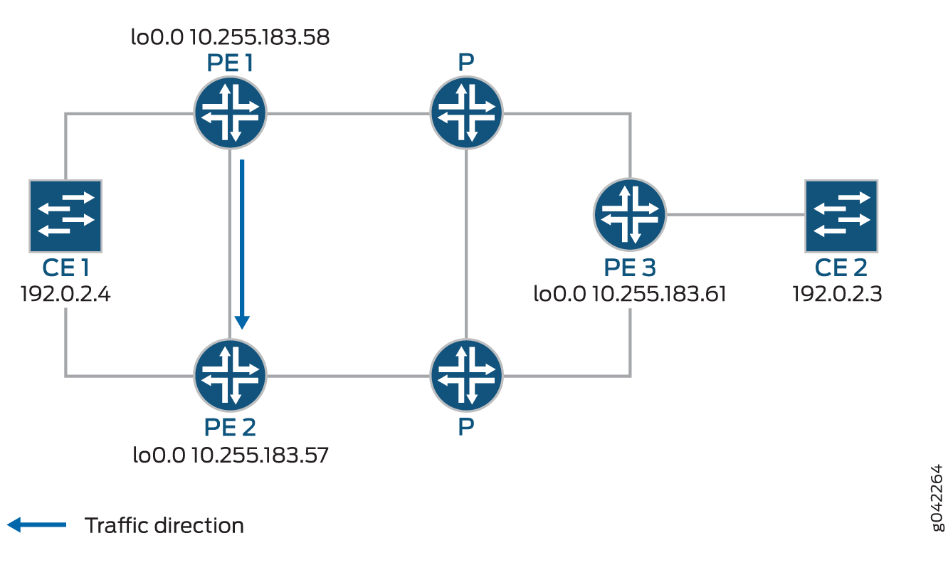
In the event of a failure of the egress PE Router PE1, traffic is switched to the egress protection LSP configured between Router PE1 and Router PE2 (the protector PE router):
Device CE2—Traffic origin
Router PE3—Ingress PE router
Router PE1— (Primary) Egress PE router
Router PE2—Protector PE router
Device CE1—Traffic destination
When the link between CE1– PE1 goes downs, PE1 will briefly redirect that traffic toward CE1, to PE2. PE2 forwards it to CE1 until ingress router PE3 recalculates to forward the traffic to PE2.
Initially the traffic direction was: CE2 – PE3 – P – PE1 – CE1.
When the link between CE1– PE1 goes down, the traffic will be: CE2 – PE3 – P – PE1 – PE2 –CE1. PE3 then recalculates the path: CE2 – PE3 – P – PE2 – CE1.
This example shows how to configure routers PE1, PE2, and PE3.
Configuration
CLI Quick Configuration
To quickly configure an egress protection
LSP, copy the following commands, paste them into a text file, remove
any line breaks, change any details necessary to match your network
configurations, copy and then paste the commands into the CLI and
enter commit from configuration mode.
PE1
set protocols rsvp interface all set protocols rsvp interface fxp0.0 disable set protocols mpls interface all set protocols mpls interface fxp0.0 disable set protocols mpls egress-protection context-identifier 198.51.100.3 primary set protocols mpls egress-protection context-identifier 198.51.100.3 advertise-mode stub-alias set protocols mpls egress-protection traceoptions file ep size 100m set protocols mpls egress-protection traceoptions flag all set protocols bgp traceoptions file bgp.log world-readable set protocols bgp group ibgp type internal set protocols bgp group ibgp local-address 10.255.183.58 set protocols bgp group ibgp family inet unicast set protocols bgp group ibgp family l2vpn signaling egress-protection set protocols bgp group ibgp neighbor 192.0.2.3 set protocols bgp group ibgp neighbor 192.0.2.4 set protocols isis traceoptions file isis-edge size 10m world-readable set protocols isis traceoptions flag error set protocols isis level 1 disable set protocols isis level 2 wide-metrics-only set protocols isis interface all point-to-point set protocols isis interface all level 2 metric 10 set protocols isis interface fxp0.0 disable set protocols ldp interface all set protocols ldp interface fxp0.0 disable set policy-options policy-statement lb then load-balance per-packet set routing-options traceoptions file ro.log set routing-options traceoptions flag all set routing-options traceoptions flag route set routing-options autonomous-system 100 set routing-options forwarding-table export lb set routing-instances foo instance-type l2vpn set routing-instances foo egress-protection context-identifier 198.51.100.3 set routing-instances foo interface ge-2/0/2.0 set routing-instances foo route-distinguisher 10.255.183.58:1 set routing-instances foo vrf-target target:9000:1 set routing-instances foo protocols l2vpn encapsulation-type ethernet-vlan set routing-instances foo protocols l2vpn site foo site-identifier 1 set routing-instances foo protocols l2vpn site foo site-preference primary set routing-instances foo protocols l2vpn site foo interface ge-2/0/2.0 remote-site-id 2
PE2
set protocols rsvp interface all set protocols rsvp interface fxp0.0 disable set protocols mpls interface all set protocols mpls interface fxp0.0 disable set protocols mpls egress-protection context-identifier 198.51.100.3 protector set protocols mpls egress-protection context-identifier 198.51.100.3 advertise-mode stub-alias set protocols mpls egress-protection traceoptions file ep size 100m set protocols mpls egress-protection traceoptions flag all set protocols bgp traceoptions file bgp.log world-readable set protocols bgp group ibgp type internal set protocols bgp group ibgp local-address 10.255.183.57 set protocols bgp group ibgp family inet unicast set protocols bgp group ibgp family l2vpn signaling egress-protection set protocols bgp group ibgp neighbor 192.0.2.3 set protocols bgp group ibgp neighbor 192.0.2.4 set protocols isis traceoptions file isis-edge size 10m world-readable set protocols isis traceoptions flag error set protocols isis level 1 disable set protocols isis level 2 wide-metrics-only set protocols isis interface all point-to-point set protocols isis interface all level 2 metric 10 set protocols isis interface fxp0.0 disable set protocols ldp interface all set protocols ldp interface fxp0.0 disable set policy-options policy-statement lb then load-balance per-packet set routing-options traceoptions file ro.log set routing-options traceoptions flag normal set routing-options traceoptions flag route set routing-options autonomous-system 100 set routing-options forwarding-table export lb set routing-instances foo instance-type l2vpn set routing-instances foo egress-protection protector set routing-instances foo interface ge-2/0/2.0 set routing-instances foo route-distinguisher 10.255.183.57:1 set routing-instances foo vrf-target target:9000:1 set routing-instances foo protocols l2vpn encapsulation-type ethernet-vlan set routing-instances foo protocols l2vpn site foo hot-standby set routing-instances foo protocols l2vpn site foo site-identifier 1 set routing-instances foo protocols l2vpn site foo site-preference backup set routing-instances foo protocols l2vpn site foo interface ge-2/0/2.0 remote-site-id 2
PE3
set protocols rsvp interface all set protocols rsvp interface fxp0.0 disable set protocols mpls interface all set protocols mpls interface fxp0.0 disable set protocols bgp traceoptions file bgp.log world-readable set protocols bgp group ibgp type internal set protocols bgp group ibgp local-address 10.255.183.61 set protocols bgp group ibgp family inet unicast set protocols bgp group ibgp family l2vpn signaling set protocols bgp group ibgp neighbor 192.0.2.3 set protocols bgp group ibgp neighbor 192.0.2.4 set protocols isis traceoptions file isis-edge size 10m world-readable set protocols isis traceoptions flag error set protocols isis level 1 disable set protocols isis level 2 wide-metrics-only set protocols isis interface all point-to-point set protocols isis interface all level 2 metric 10 set protocols isis interface fxp0.0 disable set protocols ldp interface all set protocols ldp interface fxp0.0 disable set policy-options policy-statement lb then load-balance per-packet set routing-options traceoptions file ro.log set routing-options traceoptions flag normal set routing-options traceoptions flag route set routing-options autonomous-system 100 set routing-options forwarding-table export lb set routing-instances foo instance-type l2vpn set routing-instances foo interface ge-2/1/2.0 set routing-instances foo route-distinguisher 10.255.183.61:1 set routing-instances foo vrf-target target:9000:1 set routing-instances foo protocols l2vpn encapsulation-type ethernet-vlan set routing-instances foo protocols l2vpn site foo site-identifier 2 set routing-instances foo protocols l2vpn site foo interface ge-2/1/2.0 remote-site-id 1
Step-by-Step Procedure
Step-by-Step Procedure
The following example requires you to navigate various levels in the configuration hierarchy. For information about navigating the CLI, see Using the CLI Editor in Configuration Mode.
To configure an egress protection LSP for router PE1:
Configure RSVP.
[edit protocols rsvp] user@PE1# set interface all user@PE1# set interface fxp0.0 disable
Configure MPLS to use the egress protection LSP to protect against a link failure to Device CE1.
[edit protocols mpls] user@PE1# set interface all user@PE1# set interface fxp0.0 disable user@PE1# set egress-protection context-identifier 198.51.100.3 primary user@PE1# set egress-protection context-identifier 198.51.100.3 advertise-mode stub-alias user@PE1# set egress-protection traceoptions file ep size 100m user@PE1# set egress-protection traceoptions flag all
Configure BGP.
[edit protocols bgp]
user@PE1# set traceoptions file bgp.log world-readable
user@PE1# set group ibgp type internal
user@PE1# set group ibgp local-address 10.255.183.58
user@PE1# set group ibgp family inet unicast
user@PE1# set group ibgp family l2vpn signaling egress-protection
user@PE1# set group ibgp neighbor 192.0.2.3
user@PE1# set group ibgp neighbor 192.0.2.4
Configure IS-IS.
[edit protocols isis]
user@PE1# set traceoptions file isis-edge size 10m world-readable
user@PE1# set traceoptions flag error
user@PE1# set level 1 disable
user@PE1# set level 2 wide-metrics-only
user@PE1# set interface all point-to-point
user@PE1# set interface all level 2 metric 10
user@PE1# set interface fxp0.0 disable
Configure LDP.
[edit protocols ldp]
user@PE1# set interface all
user@PE1# set interface fxp0.0 disable
Configure a load-balancing policy.
[edit]
user@PE1# set policy-options policy-statement lb then load-balance per-packet
Configure the routing options to export routes based on the load-balancing policy.
[edit routing-options]
user@PE1# set traceoptions file ro.log
user@PE1# set traceoptions flag all
user@PE1# set autonomous-system 100
user@PE1# set forwarding-table export lb
Configure BGP to advertise nrli from the routing instance with context-ID as next-hop.
[edit routing-instances]
user@PE1# set foo instance-type l2vpn
user@PE1# set foo egress-protection context-identifier 198.51.100.3
user@PE1# set foo interface ge-2/0/2.0
user@PE1# set foo route-distinguisher 10.255.183.58:1
user@PE1# set foo vrf-target target:9000:1
Configure l2vpn instance to use the egress LSP configured.
[edit routing-instances]
user@PE1# set foo protocols l2vpn encapsulation-type ethernet-vlan
user@PE1# set foo protocols l2vpn site foo site-identifier 1
user@PE1# set foo protocols l2vpn site foo site-preference primary
user@PE1# set foo protocols l2vpn site foo interface ge-2/0/2.0 remote-site-id 2
If you are done configuring the device, enter
commitfrom configuration mode.
Step-by-Step Procedure
To configure an egress protection LSP for Router PE2:
Configure RSVP.
[edit protocols rsvp]
user@PE2# set interface all
user@PE2# set interface fxp0.0 disable
Configure MPLS and the LSP that acts as the egress protection LSP.
[edit protocols mpls]
user@PE2# set interface all
user@PE2# set interface fxp0.0 disable
user@PE2# set egress-protection context-identifier 198.51.100.3 protector
user@PE2# set egress-protection context-identifier 198.51.100.3 advertise-mode stub-alias
user@PE2# set egress-protection traceoptions file ep size 100m
user@PE2# set egress-protection traceoptions flag all
Configure BGP.
[edit protocols bgp]
user@PE2# set traceoptions file bgp.log world-readable
user@PE2# set group ibgp type internal
user@PE2# set group ibgp local-address 10.255.183.57
user@PE2# set group ibgp family inet unicast
user@PE2# set group ibgp family l2vpn signaling
user@PE2# set group ibgp family l2vpn egress-protection
user@PE2# set group ibgp neighbor 192.0.2.3
user@PE2# set group ibgp neighbor 192.0.2.4
Configure IS-IS.
[edit protocols isis]
user@PE2# set traceoptions file isis-edge size 10m world-readable
user@PE2# set traceoptions flag error
user@PE2# set level 1 disable
user@PE2# set level 2 wide-metrics-only
user@PE2# set interface all point-to-point
user@PE2# set interface all level 2 metric 10
user@PE2# set interface fxp0.0 disable
Configure LDP.
[edit protocols ldp]
user@PE2# set interface all
user@PE2# set interface fxp0.0 disable
Configure a load-balancing policy.
[edit]
user@PE2# set policy-options policy-statement lb then load-balance per-packet
Configure the routing options to export routes based on the load-balancing policy.
[edit routing-options]
user@PE2# set traceoptions file ro.log
user@PE2# set traceoptions flag all
user@PE2# set autonomous-system 100
user@PE2# set forwarding-table export lb
Configure BGP to advertise nrli from the routing instance with context-ID as next-hop.
[edit routing-instances]
user@PE2# set foo instance-type l2vpn
user@PE2# set foo egress-protection protector
user@PE2# set foo interface ge-2/0/2.0
user@PE2# set foo route-distinguisher 10.255.183.57:1
user@PE2# set foo vrf-target target:9000:1
Configure l2vpn instance to use the egress LSP configured.
[edit routing-instances]
user@PE2# set foo protocols l2vpn encapsulation-type ethernet-vlan
user@PE2# set foo protocols l2vpn site foo hot-standby
user@PE2# set foo protocols l2vpn site foo site-identifier 1
user@PE2# set foo protocols l2vpn site foo site-preference backup
user@PE2# set foo protocols l2vpn site foo interface ge-2/0/2.0 remote-site-id 2
If you are done configuring the device, enter
commitfrom configuration mode.
Step-by-Step Procedure
To configure an egress protection LSP for Router PE3:
Configure RSVP.
[edit protocols rsvp]
user@PE3# set interface all
user@PE3# set interface fxp0.0 disable
Configure MPLS.
[edit protocols mpls]
user@PE3# set interface all
user@PE3# set interface fxp0.0 disable
Configure BGP.
[edit protocols bgp]
user@PE3# set traceoptions file bgp.log world-readable
user@PE3# set group ibgp type internal
user@PE3# set group ibgp local-address 10.255.183.61
user@PE3# set group ibgp family inet unicast
user@PE3# set group ibgp family l2vpn signaling
user@PE3# set group ibgp neighbor 192.0.2.3
user@PE3# set group ibgp neighbor 192.0.2.4
Configure IS-IS.
[edit protocols isis]
user@PE3# set traceoptions file isis-edge size 10m world-readable
user@PE3# set traceoptions flag error
user@PE3# set level 1 disable
user@PE3# set level 2 wide-metrics-only
user@PE3# set protocols isis interface all point-to-point
[edit protocols isis]
user@PE3# set protocols isis interface all level 2 metric 10
[edit protocols isis]
user@PE3# set protocols isis interface fxp0.0 disable
Configure LDP.
[edit protocols ldp]
user@PE3# set interface all
user@PE3# set interface fxp0.0 disable
Configure a load-balancing policy.
[edit]
user@PE3# set policy-options policy-statement lb then load-balance per-packet
Configure the routing options to export routes based on the load-balancing policy.
[edit routing-options]
user@PE3# set traceoptions file ro.log
user@PE3# set traceoptions flag normal
user@PE3# set traceoptions flag route
user@PE3# set autonomous-system 100
user@PE3# set forwarding-table export lb
Configure BGP to advertise nlri from the routing instance with context-ID as next-hop.
[edit]
user@PE3# set routing-instances foo instance-type l2vpn
user@PE3# set routing-instances foo interface ge-2/1/2.0
user@PE3# set routing-instances foo route-distinguisher 10.255.183.61:1
user@PE3# set routing-instances foo vrf-target target:9000:1
Configure l2vpn to specify the interface that connects to the site and the remote interface to which you want the specified interface to connect.
[edit routing-instances]
user@PE3# set foo protocols l2vpn encapsulation-type ethernet-vlan
user@PE3# set foo protocols l2vpn site foo site-identifier 2
user@PE3# set foo protocols l2vpn site foo interface ge-2/1/2.0 remote-site-id 1
If you are done configuring the device, enter
commitfrom configuration.
Results
From configuration mode, confirm your configuration on Router PE1 by entering the show protocols, show policy-options, and show routing-options commands. If the output does not display the intended configuration, repeat the instructions in this example to correct the configuration.
[edit]
user@PE1# show protocols
rsvp {
    interface all;
    interface fxp0.0 {
        disable;
    }
}
mpls {
    interface all;
    interface fxp0.0 {
        disable;
    }
    egress-protection {
        context-identifier 198.51.100.3 {
            primary;
            advertise-mode stub-alias;
        }
        traceoptions {
            file ep size 100m;
            flag all;
        }
    }
}
bgp {
    traceoptions {
        file bgp.log world-readable;
    }
    group ibgp {
        type internal;
        local-address 10.255.183.58;
        family inet {
            unicast;
        }
        family l2vpn {
            signaling {
                egress-protection;
            }
        }
        neighbor 192.0.2.3;
        neighbor 192.0.2.4;
    }
}
isis {
    traceoptions {
        file isis-edge size 10m world-readable;
        flag error;
    }
    level 1 disable;
    level 2 wide-metrics-only;
    interface all {
        point-to-point;
        level 2 metric 10;
    }
    interface fxp0.0 {
        disable;
    }
}
ldp {
    interface all;
    interface fxp0.0 {
        disable;
    }
}

[edit]
user@PE1# show policy-options
policy-statement lb {
    then {
        load-balance per-packet;
    }
}
[edit]
user@PE1# show routing-options
traceoptions {
    file ro.log;
    flag all;
}
autonomous-system 100;
forwarding-table {
    export lb;
}

[edit]
user@PE1# show routing-instances
foo {
    instance-type l2vpn;
    egress-protection {
        context-identifier {
            198.51.100.3;
        }
    }
    interface ge-2/0/2.0;
    route-distinguisher 10.255.183.58:1;
    vrf-target target:9000:1;
    protocols {
        l2vpn {
            encapsulation-type ethernet-vlan;
            site foo {
                site-identifier 1;
                site-preference primary;
                interface ge-2/0/2.0 {
                    remote-site-id 2;
                }
            }
        }
    }
}
From configuration mode, confirm your configuration on Router PE2 by entering the show protocols, show policy-options, and show routing-options commands. If the output does not display the intended configuration, repeat the instructions in this example to correct the configuration.
[edit]
user@PE2# show protocols
rsvp {
    interface all;
    interface fxp0.0 {
        disable;
    }
}
mpls {
    interface all;
    interface fxp0.0 {
        disable;
    }

    egress-protection {
        context-identifier 198.51.100.3 {
            protector;
            advertise-mode stub-alias;
        }
        traceoptions {
            file ep size 100m;
            flag all;
        }
    }
}
bgp {
    traceoptions {
        file bgp.log world-readable;
    }
    group ibgp {
        type internal;
        local-address 10.255.183.57;
        family inet {
            unicast;
        }
        family l2vpn {
            signaling {
                egress-protection;
            }
        }
        neighbor 192.0.2.3;
        neighbor 192.0.2.4;
    }
}
isis {
    traceoptions {
        file isis-edge size 10m world-readable;
        flag error;
    }
    level 1 disable;
    level 2 wide-metrics-only;
    interface all {
        point-to-point;
        level 2 metric 10;
    }
    interface fxp0.0 {
        disable;
    }
}
ldp {
    interface all;
    interface fxp0.0 {
        disable;
    }
}

[edit]
user@PE2# show policy-options
policy-statement lb {
    then {
        load-balance per-packet;
    }
}

[edit]
user@PE2# show routing-options
traceoptions {
    file ro.log;
    flag normal;
    flag route;
}
autonomous-system 100;
forwarding-table {
    export lb;
}

[edit]
user@PE2# show routing-instances
foo {
    instance-type l2vpn;
    egress-protection {
        protector;
    }
    interface ge-2/0/2.0;
    route-distinguisher 10.255.183.57:1;
    vrf-target target:9000:1;
    protocols {
        l2vpn {
            encapsulation-type ethernet-vlan;
            site foo {
                hot-standby;
                site-identifier 1;
                site-preference backup;
                interface ge-2/0/2.0 {
                    remote-site-id 2;
                }
            }
        }
    }
}
From configuration mode, confirm your configuration on Router PE3 by entering the show protocols, show policy-options, and show routing-options commands. If the output does not display the intended configuration, repeat the instructions in this example to correct the configuration.
[edit]
user@PE3# show protocols
rsvp {
    interface all;
    interface fxp0.0 {
        disable;
    }
}
mpls {
    interface all;
    interface fxp0.0 {
        disable;
    }
}
bgp {
    traceoptions {
        file bgp.log world-readable;
    }
    group ibgp {
        type internal;
        local-address 10.255.183.61;
        family inet {
            unicast;
        }
        family l2vpn {
            signaling;
        }
        neighbor 192.0.2.3;
        neighbor 192.0.2.4;
    }
}
isis {
    traceoptions {
        file isis-edge size 10m world-readable;
        flag error;
    }
    level 1 disable;
    level 2 wide-metrics-only;
    interface all {
        point-to-point;
        level 2 metric 10;
    }
    interface fxp0.0 {
        disable;
    }
}
ldp {
    interface all;
    interface fxp0.0 {
        disable;
    }
}

[edit]
user@PE3# show policy-options
policy-statement lb {
    then {
        load-balance per-packet;
    }
}

[edit]
user@PE3# show routing-options
traceoptions {
    file ro.log;
    flag normal;
    flag route;
}
autonomous-system 100;
forwarding-table {
    export lb;
}

[edit]
user@PE3# show routing-instances
foo {
    instance-type l2vpn;
    interface ge-2/1/2.0;
    route-distinguisher 10.255.183.61:1;
    vrf-target target:9000:1;
    protocols {
        l2vpn {
            encapsulation-type ethernet-vlan;
            site foo {
                site-identifier 2;
                interface ge-2/1/2.0 {
                    remote-site-id 1;
                }
            }
        }
    }
}
Verification
Confirm that the configuration is working properly.
- Verifying the L2VPN Configuration
- Verifying the Routing Instance Details
- Verifying the IS-IS Configuration
- Verifying the MPLS Configuration
Verifying the L2VPN Configuration
Purpose
Verify that LSP is protected by the connection protection logic.
Action
From operational mode, run the show l2vpn connections
extensive command.
user@PE2> show l2vpn connections extensive
Layer-2 VPN connections:
Legend for connection status (St)
EI -- encapsulation invalid      NC -- interface encapsulation not CCC/TCC/VPLS
EM -- encapsulation mismatch     WE -- interface and instance encaps not same
VC-Dn -- Virtual circuit down    NP -- interface hardware not present
CM -- control-word mismatch      -> -- only outbound connection is up
CN -- circuit not provisioned    <- -- only inbound connection is up
OR -- out of range               Up -- operational
OL -- no outgoing label          Dn -- down
LD -- local site signaled down   CF -- call admission control failure
RD -- remote site signaled down  SC -- local and remote site ID collision
LN -- local site not designated  LM -- local site ID not minimum designated
RN -- remote site not designated RM -- remote site ID not minimum designated
XX -- unknown connection status  IL -- no incoming label
MM -- MTU mismatch               MI -- Mesh-Group ID not available
BK -- Backup connection          ST -- Standby connection
PF -- Profile parse failure      PB -- Profile busy
RS -- remote site standby        SN -- Static Neighbor
LB -- Local site not best-site   RB -- Remote site not best-site
VM -- VLAN ID mismatch
Legend for interface status
Up -- operational
Dn -- down
Instance: foo
Local site: foo (1)
   connection-site           Type  St  Time last up          # Up trans
    2                         rmt   Up  Aug  3 00:08:14 2001           1
      Local circuit: ge-2/0/2.0, Status: Up
      Remote PE: 192.0.2.3
      Incoming label: 32769, Outgoing label: 32768
      Egress Protection: Yes
        Time                  Event            Interface/Lbl/PE
        Aug  3 00:08:14 2001  PE route up
        Aug  3 00:08:14 2001  Out lbl Update               32768
        Aug  3 00:08:14 2001  In lbl Update                32769
        Aug  3 00:08:14 2001  ckt0 up                 fe-0/0/0.0
Meaning
The Egress Protection: Yes output shows
that the given PVC is protected by connection protection logic.
Verifying the Routing Instance Details
Purpose
Verify the routing instance information and the context identifier configured on the primary, which is used as the next-hop address in case of node-link failure.
Action
From operational mode, run the show route foo detail command.
user@PE2> show route foo detail
foo:
  Router ID: 0.0.0.0
  Type: l2vpn non-forwarding State: Active
  Interfaces:
    lt-1/2/0.56
  Route-distinguisher: 10.255.255.11:1
  Vrf-import: [ __vrf-import-foo-internal__ ]
  Vrf-export: [ __vrf-export-foo-internal__ ]
  Vrf-import-target: [ target:100:200 ]
  Vrf-export-target: [ target:100:200 ]
  Fast-reroute-priority: low
  Vrf-edge-protection-id:  198.51.100.3
  Tables:
    foo.l2vpn.0           : 5 routes (3 active, 0 holddown, 0 hidden)
    foo.l2id.0            : 6 routes (2 active, 0 holddown, 0 hidden)
Meaning
The context-id is set to 198.51.100.3 and
the Vrf-import: [ __vrf-import-foo-internal__] in the output
mentions the policy used for rewriting the next-hop address.
Verifying the IS-IS Configuration
Purpose
Verify the IS-IS context identifier information.
Action
From operational mode, run the show isis context-identifier
detail command.
user@PE2> show isis context-identifier detail
IS-IS context database:
Context               L  Owner     Role       Primary      Metric
198.51.100.3             2  MPLS      Protector  pro17-b-lr-R1 0
  Advertiser pro17-b, Router ID 10.255.107.49, Level 2, tlv protector
  Advertiser pro17-b-lr-R1, Router ID 10.255.255.11, Metric 1, Level 2, tlv prefix
Meaning
Router PE2 is the protector and the configured context identifier is in use for the MPLS protocol.
Verifying the MPLS Configuration
Purpose
Verify the context identifier details on the primary and protector PEs.
Action
From operational mode, run the show mpls context-identifier
detail command.
user@PE1> show mpls context-identifier detail
ID: 198.51.100.3
  Type: primary, Metric: 1, Mode: alias

Total 1, Primary 1, Protector 0
user@PE2> show mpls context-identifier detail
ID: 198.51.100.3
  Type: protector, Metric: 16777215, Mode: alias
  Context table: __198.51.100.3__.mpls.0, Label out: 299968
user@PE2> show mpls egress-protection detail
Instance                 Type      Protection-Type
foo                    local-l2vpn Protector
  Route Target 100:200
Meaning
Context-id is 198.51.100.3, advertise-mode
is alias, the MPLS table created for egress protection
is __198.51.100.3__.mpls.0, and the egress instance name
is foo, which is of type local-l2vpn.
Change History Table
Feature support is determined by the platform and release you are using. Use Feature Explorer to determine if a feature is supported on your platform.