Understanding Multisegment Pseudowire for FEC 129
Understanding Multisegment Pseudowire
A pseudowire is a Layer 2 circuit or service that emulates the essential attributes of a telecommunications service, such as a T1 line, over an MPLS packet-switched network (PSN). The pseudowire is intended to provide only the minimum necessary functionality to emulate the wire with the required resiliency requirements for the given service definition.
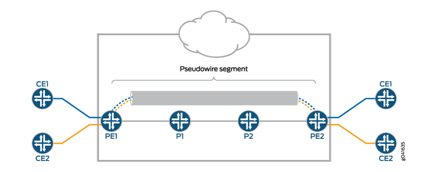
When a pseudowire originates and terminates on the edge of the same PSN, the pseudowire label is unchanged between the originating and terminating provider edge (T-PE) devices. This is called a single-segment pseudowire (SS-PW). Figure 1 illustrates an SS-PW established between two PE routers. The pseudowires between the PE1 and PE2 routers are located within the same autonomous system (AS).
In cases where it is impossible to establish a single pseudowire from a local to a remote PE, either because it is unfeasible or undesirable to establish a single control plane between the two PEs, a multisegment pseudowire (MS-PW) is used.
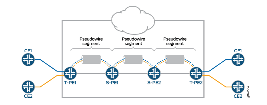
An MS-PW is a set of two or more contiguous SS-PWs that are made to function as a single point-to-point pseudowire. It is also known as switched pseudowire. MS-PWs can go across different regions or network domains. A region can be considered as an interior gateway protocol (IGP) area or a BGP autonomous system that belongs to the same or different administrative domain. An MS-PW spans multiple cores or ASs of the same or different carrier networks. A Layer 2 VPN MS-PW can include up to 254 pseudowire segments.
Figure 2 illustrates a set of two or more pseudowire segments that function as a single pseudowire. The end routers are called terminating PE (T-PE) routers, and the switching routers are called switching PE (S-PE) routers. The S-PE router terminates the tunnels of the preceding and succeeding pseudowire segments in an MS-PW. The S-PE router can switch the control and data planes of the preceding and succeeding pseudowire segments of the MS-PW. An MS-PW is declared to be up when all the single-segment pseudowires are up.
Using FEC 129 for Multisegment Pseudowire
Currently, there are two types of attachment circuit identifiers (AIIs) defined under FEC 129:
Type 1 AII
Type 2 AII
The support of an MS-PW for FEC 129 uses type 2 AII. A type 2 AII is globally unique by definition of RFC 5003.
Single-segment pseudowires (SS-PWs) using FEC 129 on an MPLS PSN can use both type 1 and type 2 AII. For an MS-PW using FEC 129, a pseudowire itself is identified as a pair of endpoints. This requires that the pseudowire endpoints be uniquely identified.
In the case of a dynamically placed MS-PW, there is a requirement for the identifiers of attachment circuits to be globally unique, for the purposes of reachability and manageability of the pseudowire. Thus, individual globally unique addresses are allocated to all the attachment circuits and S-PEs that make up an MS-PW.
Type 2 AII is composed of three fields:
Global_ID—Global identification, which is usually the AS number.
Prefix—IPv4 address, which is usually the router ID.
AC_ID—Local attachment circuit, which is a user-configurable value.
Since type 2 AII already contains the T-PE's IP address and it is globally unique, from the FEC 129 pseudowire signaling point of view, the combination (AGI, SAII, TAII) uniquely identifies an MS-PW across all interconnected pseudowire domains.
Establishing a Multisegment Pseudowire Overview
An MS-PW is established by dynamically and automatically selecting the predefined S-PEs and placing the MS-PW between two T-PE devices.
When S-PEs are dynamically selected, each S-PE is automatically discovered and selected using the BGP autodiscovery feature, without the requirement of provisioning the FEC 129 pseudowire-related information on all the S-PEs. BGP is used to propagate pseudowire address information throughout the PSN.
Since there is no manual provisioning of FEC 129 pseudowire information on the S-PEs, the Attachment Group Identifier (AGI) and Attachment Individual Identifier (AII) are reused automatically, and choosing the same set of S-PEs for the pseudowire in both the forwarding and reverse direction is achieved through the active and passive role of each T-PE device.
Active—The T-PE initiates an LDP label mapping message.
Passive—The T-PE does not initiate an LDP label mapping message until it receives a label mapping message initiated by the active T-PE. The passive T-PE sends its label mapping message to the same S-PE from where it received the label mapping message originated from its active T-PE. This ensures that the same set of S-PEs are used in the reverse direction.
Pseudowire Status Support for Multisegment Pseudowire
Pseudowire Status Behavior on T-PE
The following pseudowire status messages are relevant on the T-PE:
0x00000010—Local PSN-facing pseudowire (egress) transmit fault.
0x00000001—Generic nonforwarding fault code. This is set as the local fault code. The local fault code is set at the local T-PE, and LDP sends a pseudowire status TLV message with the same fault code to the remote T-PE.
Fault codes are bit-wise OR’ed and stored as remote pseudowire status codes.
Pseudowire Status Behavior on S-PE
The S-PE initiates the pseudowire status messages that indicate the pseudowire faults. The SP-PE in the pseudowire notification message hints where the fault was originated.
When a local fault is detected by the S-PE, a pseudowire status message is sent in both directions along the pseudowire. Since there are no attachment circuits on an S-PE, only the following status messages are relevant:
0x00000008—Local PSN-facing pseudowire (ingress) receive fault.
0x00000010—Local PSN-facing pseudowire (egress) transmit fault.
To indicate which SS-PW is at fault, an LDP SP-PE TLV is attached with the pseudowire status code in the LDP notification message. The pseudowire status is passed along from one pseudowire to another unchanged by the control plane switching function.
If an S-PE initiates a pseudowire status notification message with one particular pseudowire status bit, then for the pseudowire status code an S-PE receives, the same bit is processed locally and not forwarded until the S-PE's original status error is cleared.
An S-PE keeps only two pseudowire status codes for each SS-PW it is involved in – local pseudowire status code and remote pseudowire status code. The value of the remote pseudowire status code is the result of logic or operation of the pseudowire status codes in the chain of SS-PWs preceding this segment. This status code is incrementally updated by each S-PE upon receipt and communicated to the next S-PE. The local pseudowire status is generated locally based on its local pseudowire status.
Only transmit fault is detected at the SP-PE. When there is no MPLS LSP to reach the next segment, a local transmit fault is detected. The transmit fault is sent to the next downstream segment, and the receive fault is sent to the upstream segment.
Remote failures received on an S-PE are just passed along the MS-PW unchanged. Local failures are sent to both segments of the pseudowire that the S-PE is involved in.
Pseudowire TLV Support for MS-PW
MS-PW provides the following support for the LDP SP-PE TLV [RFC 6073]:
The LDP SP-PE TLVs for an MS-PW include:
Local IP address
Remote IP address
An SP-PE adds the LDP SP-PE TLV to the label mapping message. Each SP-PE appends the local LDP SP-PE TLV to the SP-PE list it received from the other segment.
The pseudowire status notification message includes the LDP SP-PE TLV when the notification is generated at the SP-PE.
Supported and Unsupported Features
Junos OS supports the following features with MS-PW:
MPLS PSN for each SS-PW that builds up the MS-PW.
The same pseudowire encapsulation for each SS-PW in an MS-PW – Ethernet or VLAN-CCC.
The generalized PWid FEC with T-LDP as an end-to-end pseudowire signaling protocol to set up each SS-PW.
MP-BGP to autodiscover the two endpoint PEs for each SS-PW associated with the MS-PW.
Standard MPLS operation to stitch two side-by-side SS-PWs to form an MS-PW.
Automatic discovery of S-PE so that the MS-PW can be dynamically placed.
Minimum provisioning of S-PE.
Operation, administration, and maintenance (OAM) mechanisms, including end-to-end MPLS ping or end-to-any-S-PE MPLS ping, MPLS path trace, end-to-end VCCV, and Bidirectional Forwarding Detection (BFD).
Pseudowire swithing point (SP) PE TLV for the MS-PW.
Composite next hop on MS-PW.
Pseudowire status TLV for MS-PW.
Junos OS does not support the following MS-PW functionality:
Mix of LDP FEC 128 and LDP FEC 129.
Static pseudowire where each label is provisioned staticially.
Graceful Routing Engine switchover.
Nonstop active routing.
Multihoming.
Partial connectivity verification (originating from an S-PE) in OAM.