Virtual Chassis Cabling
You can install EX and QFX switches in a single rack or multiple racks, or in different wiring closets, and interconnect them to form a virtual chassis. Depending upon your device, you might have dedicated virtual chassis ports (VCPs) or network ports configured as VCPs. You can also configure the ports on uplink modules as VCPs.
You can physically connect the virtual chassis member switches in a ring topology, a mesh topology, or a chain topology.
-
Ring Topology
We recommend using a ring topology when cabling a virtual chassis. In a ring topology, each switch is connected to the preceding switch and the following switch. The switches at the edges are connected to each other. If one of the links goes down, the virtual chassis will be intact because of the circular structure and redundant links.
Figure 1 show the switches mounted on a single rack or cabinet connected in a ring topology.
Figure 1: Virtual Chassis Switches on a Single Rack Connected in a Ring Topology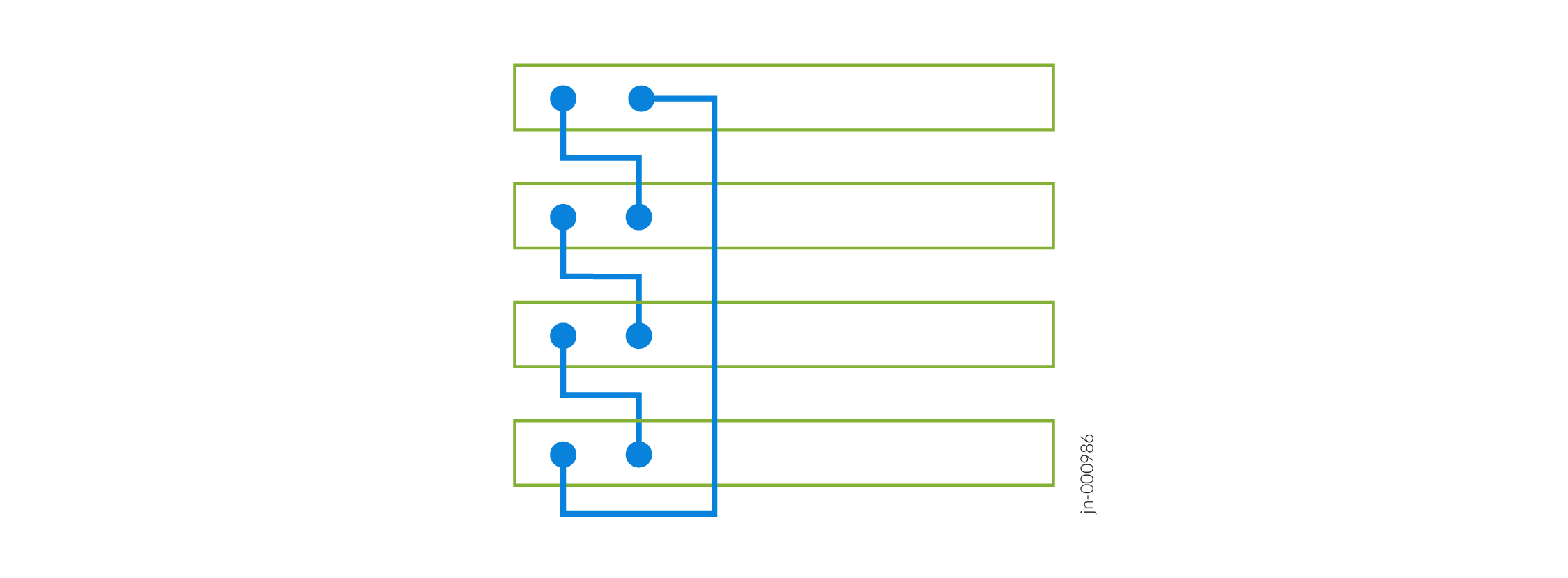 Figure 2: Virtual Chassis Switches on a Single Rack Connected in a Ring Topology (Alternative)
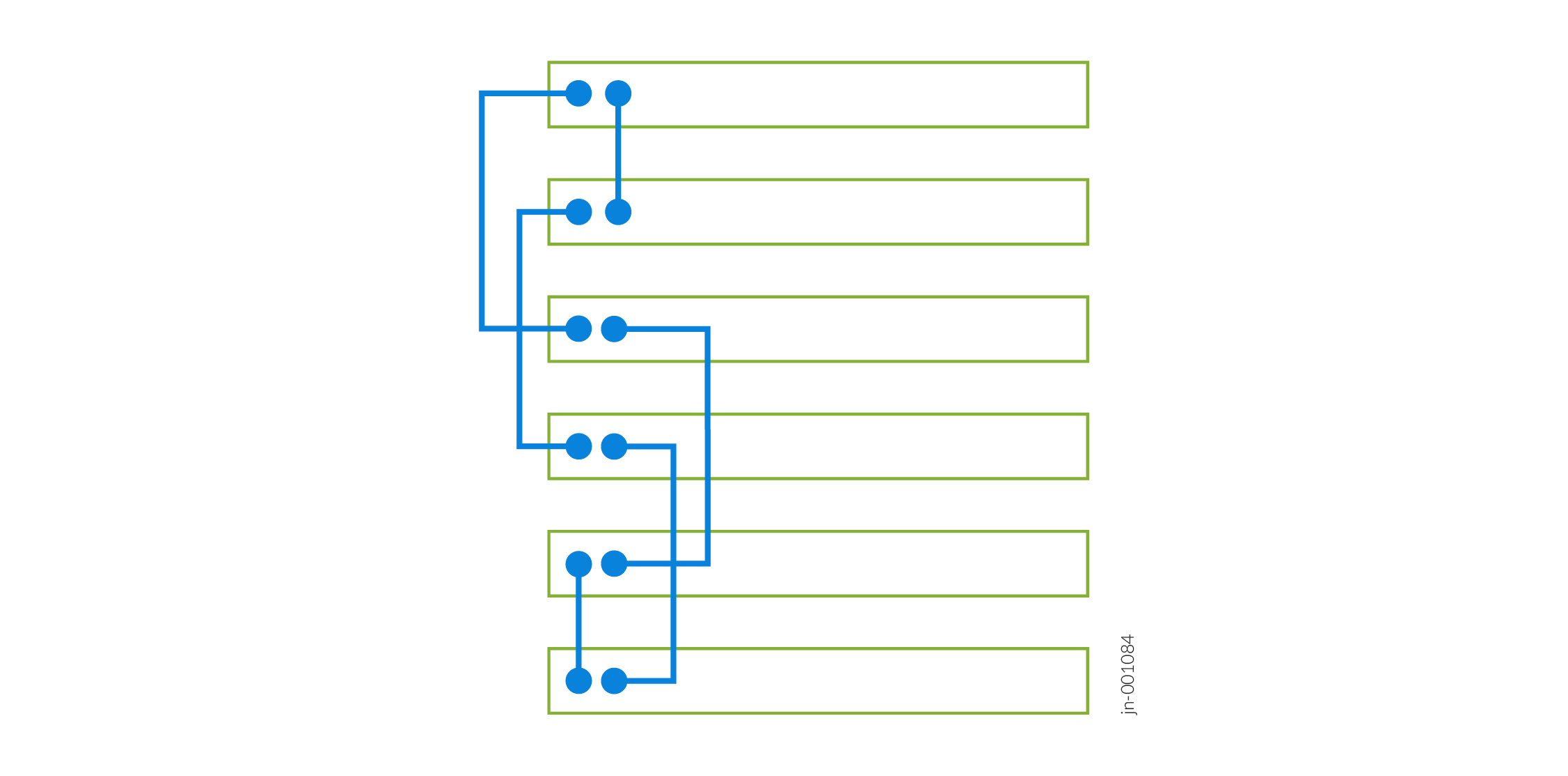
Figure 3shows the switches mounted on different racks or cabinets connected in a ring topology.
Figure 3: Virtual Chassis Switches on Different Racks Connected in a Ring Topology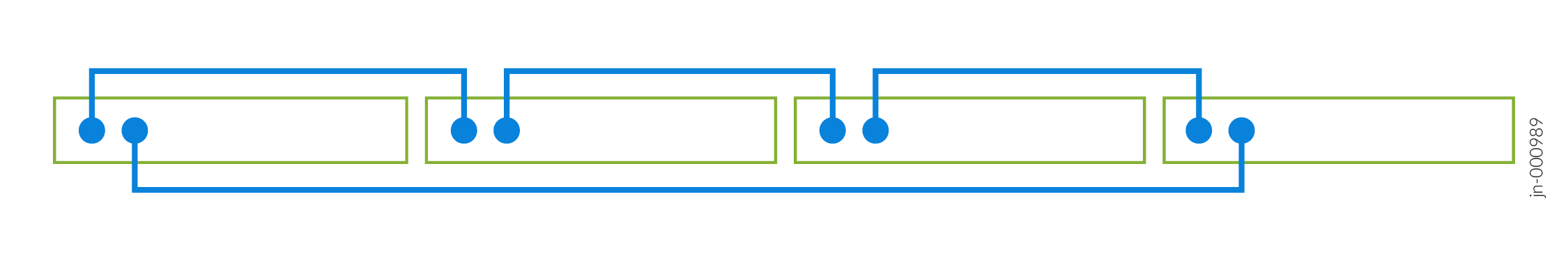
-
Mesh Topology
In a mesh topology, each switch is connected to all other switches in a fully redundant structure. The virtual chassis is intact even if multiple links go down. However, this topology is not scalable in larger virtual chassis as it uses a large number of VCPs.
Figure 4 shows the switches mounted on a single rack or cabinet connected in a mesh topology.
Figure 4: Virtual Chassis Switches on a Single Rack Connected in a Mesh Topology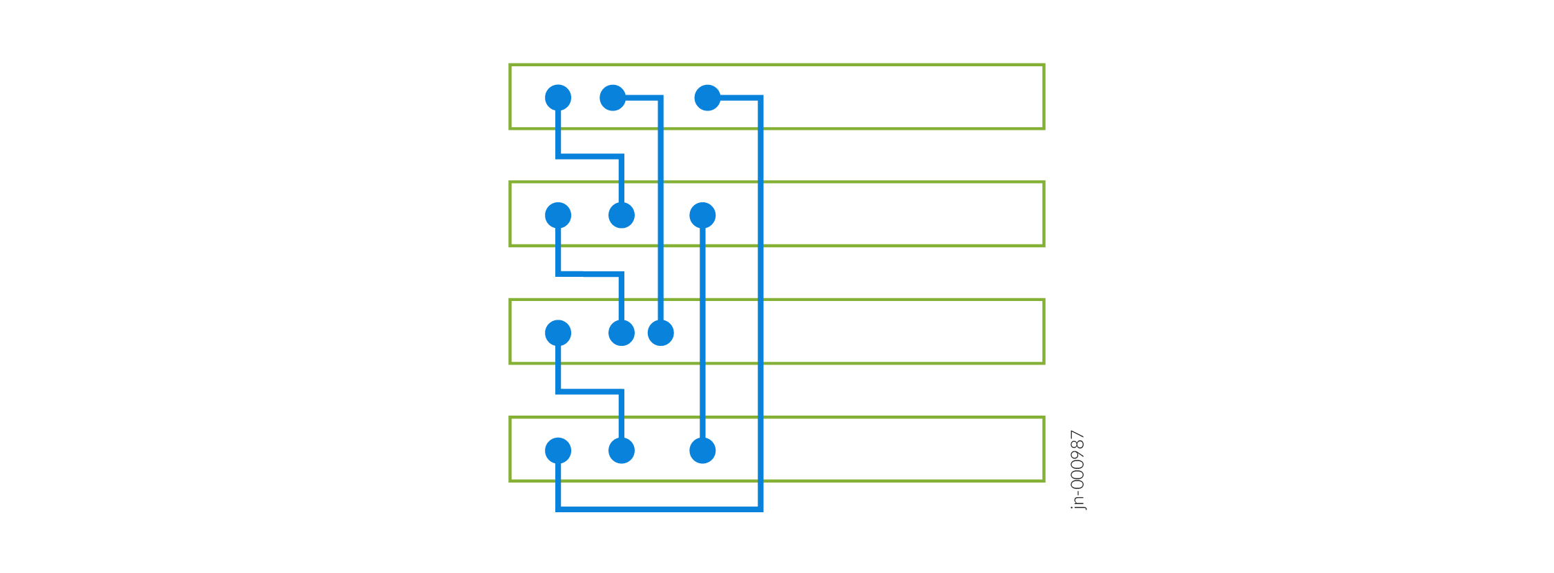
Figure 5 shows the switches mounted on different racks or cabinets connected in a mesh topology.
Figure 5: Virtual Chassis Switches on Different Racks Connected in a Mesh Topology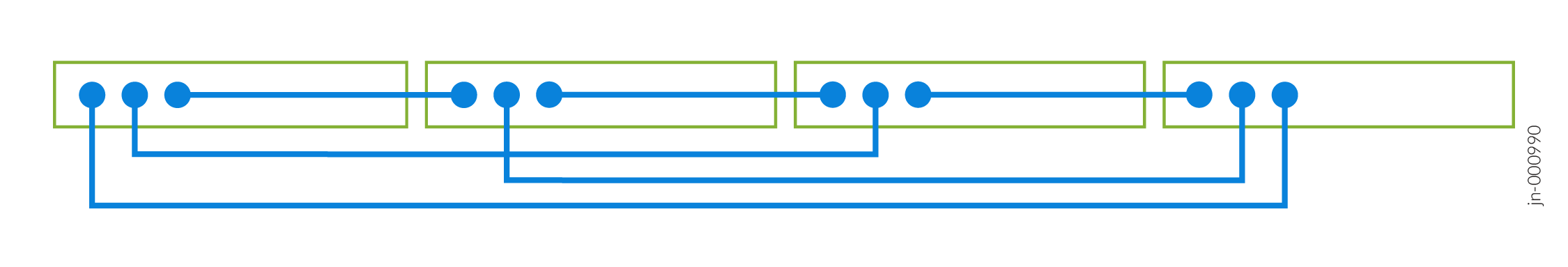
-
Chain Topology
In a chain topology, the switches are connected in a linear structure. The switches at the end are not connected to each other. If one of the links goes down, the virtual chassis is split into two and exhibits unexpected behavior.
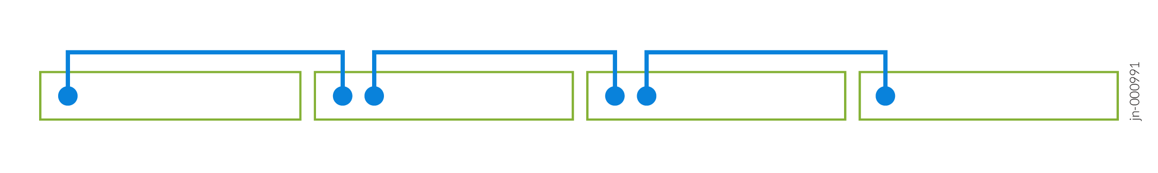
Figure 6 shows the switches mounted on a single rack or cabinet connected in a chain topology.
Figure 6: Virtual Chassis Switches on a Single Rack Connected in a Chain Topology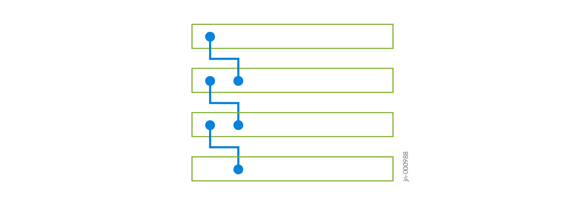
Figure 7 shows the switches mounted on different racks or cabinets connected in a ring topology.
Figure 7: Virtual Chassis Switches on Different Racks Connected in a Chain Topology