ON THIS PAGE
Example: Configuring CoS for FCoE Transit Switch Traffic Across an MC-LAG
Multichassis link aggregation groups (MC-LAGs) provide redundancy and load balancing between two switches, multihoming support for client devices such as servers, and a loop-free Layer 2 network without running Spanning Tree Protocol (STP).
This example uses Junos OS without support for the Enhanced Layer 2 Software (ELS) configuration style. If your switch runs software that does support ELS, see Example: Configuring CoS Using ELS for FCoE Transit Switch Traffic Across an MC-LAG. For ELS details, see Using the Enhanced Layer 2 Software CLI.
You can use an MC-LAG to provide a redundant aggregation layer for Fibre Channel over Ethernet (FCoE) traffic in an inverted-U topology. To support lossless transport of FCoE traffic across an MC-LAG, you must configure the appropriate class of service (CoS) on both of the switches with MC-LAG port members. The CoS configuration must be the same on both of the MC-LAG switches because an MC-LAG does not carry forwarding class and IEEE 802.1p priority information.
This example describes how to configure CoS to provide lossless transport for FCoE traffic across an MC-LAG that connects two switches. It also describes how to configure CoS on the FCoE transit switches that connect FCoE hosts to the two switches that form the MC-LAG.
This example does not describe how to configure the MC-LAG itself. However, this example includes a subset of MC-LAG configuration that only shows how to configure interface membership in the MC-LAG.
Ports that are part of an FCoE-FC gateway configuration (a virtual FCoE-FC gateway fabric) do not support MC-LAGs. Ports that are members of an MC-LAG act as FCoE pass-through transit switch ports.
Requirements
This example uses the following hardware and software components:
Two Juniper Networks switches that form an MC-LAG for FCoE traffic.
Two Juniper Networks switches that provide FCoE server access in transit switch mode and that connect to the MC-LAG switches.
FCoE servers (or other FCoE hosts) connected to the transit switches.
Junos OS Release 12.2 or later for the QFX Series.
Overview
FCoE traffic requires lossless transport. This example shows you how to:
Configure CoS for FCoE traffic on the two switches that form the MC-LAG, including priority-based flow control (PFC) and enhanced transmission selection (ETS; hierarchical scheduling of resources for the FCoE forwarding class priority and for the forwarding class set priority group).
Note:Configuring or changing PFC on an interface blocks the entire port until the PFC change is completed. After a PFC change is completed, the port is unblocked and traffic resumes. Blocking the port stops ingress and egress traffic, and causes packet loss on all queues on the port until the port is unblocked.
Configure CoS for FCoE on the two FCoE transit switches that connect FCoE hosts to the MC-LAG switches and enable FIP snooping on the FCoE VLAN at the FCoE transit switch access ports.
Disable IGMP snooping on the FCoE VLAN.
Configure the appropriate port mode, MTU, and FCoE trusted or untrusted state for each interface to support lossless FCoE transport.
Topology
Switches that act as transit switches support MC-LAGs for FCoE traffic in an inverted-U network topology, as shown in Figure 1.
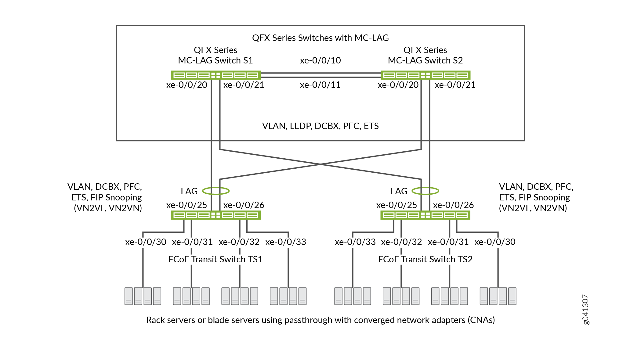
Table 1 shows the configuration components for this example.
Component |
Settings |
|---|---|
Hardware |
Four switches (two to form the MC-LAG as pass-through transit switches and two transit switches for FCoE access). |
Forwarding class (all switches) |
Default |
Classifier (forwarding class mapping of incoming traffic to IEEE priority) |
Default IEEE 802.1p trusted classifier on all FCoE interfaces. |
LAGs and MC-LAG |
S1—Ports xe-0/0/10 and x-0/0/11 are members of
LAG ae0, which connects Switch S1 to Switch S2.Ports
xe-0/0/20 and xe-0/0/21 are members of MC-LAG ae1.All
ports are configured in S2—Ports xe-0/0/10 and x-0/0/11 are members of LAG ae0,
which connects Switch S2 to Switch S1.Ports xe-0/0/20
and xe-0/0/21 are members of MC-LAG ae1.All ports
are configured in Note:
Ports xe-0/0/20 and xe-0/0/21 on Switches S1 and S2 are the members of the MC-LAG. TS1—Ports xe-0/0/25 and x-0/0/26 are members of LAG ae1,
configured in TS2—Ports xe-0/0/25 and x-0/0/26 are members of LAG ae1,
configured in |
FCoE queue scheduler (all switches) |
|
Forwarding class-to-scheduler mapping (all switches) |
Scheduler map |
Forwarding class set (FCoE priority group, all switches) |
Egress interfaces:
|
Traffic control profile (all switches) |
|
PFC congestion notification profile (all switches) |
Ingress interfaces:
|
FCoE VLAN name and tag ID |
Name— Include the FCoE VLAN on the interfaces that carry FCoE traffic on all four switches. Disable IGMP snooping on the interfaces that belong to the FCoE VLAN on all four switches. |
FIP snooping |
Enable FIP snooping on Transit Switches TS1 and TS2 on the FCoE VLAN. Configure the LAG interfaces that connect to the MC-LAG switches as FCoE trusted interfaces so that they do not perform FIP snooping. This example enables VN2VN_Port FIP snooping on the FCoE transit switch interfaces connected to the FCoE servers. The example is equally valid with VN2VF_Port FIP snooping enabled on the transit switch access ports. The method of FIP snooping you enable depends on your network configuration. |
This example uses the default IEEE 802.1p trusted BA classifier, which is automatically applied to trunk mode and tagged access mode ports if you do not apply an explicitly configured classifier.
To configure CoS for FCoE traffic across an MC-LAG:
Use the default FCoE forwarding class and forwarding-class-to-queue mapping (do not explicitly configure the FCoE forwarding class or output queue). The default FCoE forwarding class is
fcoe, and the default output queue is queue3.Note:You can include the no-loss packet drop attribute in the explicit forwarding class configuration to configure a lossless forwarding class.
Use the default trusted BA classifier, which maps incoming packets to forwarding classes by the IEEE 802.1p code point (CoS priority) of the packet. The trusted classifier is the default classifier for interfaces in trunk and tagged-access port modes. The default trusted classifier maps incoming packets with the IEEE 802.1p code point 3 (
011) to the FCoE forwarding class. If you choose to configure the BA classifier instead of using the default classifier, you must ensure that FCoE traffic is classified into forwarding classes in exactly the same way on both MC-LAG switches. Using the default classifier ensures consistent classifier configuration on the MC-LAG ports.Configure a congestion notification profile that enables PFC on the FCoE code point (code point
011in this example). The congestion notification profile configuration must be the same on both MC-LAG switches.Apply the congestion notification profile to the interfaces.
Configure enhanced transmission selection (ETS, also known as hierarchical scheduling) on the interfaces to provide the bandwidth required for lossless FCoE transport. Configuring ETS includes configuring bandwidth scheduling for the FCoE forwarding class, a forwarding class set (priority group) that includes the FCoE forwarding class, and a traffic control profile to assign bandwidth to the forwarding class set that includes FCoE traffic.
Apply the ETS scheduling to the interfaces.
Configure the port mode, MTU, and FCoE trusted or untrusted state for each interface to support lossless FCoE transport.
In addition, this example describes how to enable FIP snooping on the Transit Switch TS1 and TS2 ports that are connected to the FCoE servers and how to disable IGMP snooping on the FCoE VLAN. To provide secure access, FIP snooping must be enabled on the FCoE access ports.
This example focuses on the CoS configuration to support lossless FCoE transport across an MC-LAG. This example does not describe how to configure the properties of MC-LAGs and LAGs, although it does show you how to configure the port characteristics required to support lossless transport and how to assign interfaces to the MC-LAG and to the LAGs.
Before you configure CoS, configure:
The MC-LAGs that connect Switches S1 and S2 to Switches TS1 and TS2.
The LAGs that connect the Transit Switches TS1 and TS2 to MC-LAG Switches S1 and S2.
The LAG that connects Switch S1 to Switch S2.
Configuration
To configure CoS for lossless FCoE transport across an MC-LAG, perform these tasks:
- CLI Quick Configuration
- Configuring MC-LAG Switches S1 and S2
- Configuring FCoE Transit Switches TS1 and TS2
- Results
CLI Quick Configuration
To quickly configure CoS for lossless FCoE
transport across an MC-LAG, copy the following commands, paste them
in a text file, remove line breaks, change variables and details to
match your network configuration, and then copy and paste the commands
into the CLI for MC-LAG Switch S1 and MC-LAG Switch S2 at the [edit] hierarchy level. The configurations on Switches S1 and
S2 are identical because the CoS configuration must be identical,
and because this example uses the same ports on both switches.
Switch S1 and Switch S2
set class-of-service schedulers fcoe-sched priority low transmit-rate 3g
set class-of-service schedulers fcoe-sched shaping-rate percent 100
set class-of-service scheduler-maps fcoe-map forwarding-class fcoe scheduler fcoe-sched
set class-of-service forwarding-class-sets fcoe-pg class fcoe
set class-of-service traffic-control-profiles fcoe-tcp scheduler-map fcoe-map guaranteed-rate 3g
set class-of-service traffic-control-profiles fcoe-tcp shaping-rate percent 100
set class-of-service interfaces ae0 forwarding-class-set fcoe-pg output-traffic-control-profile fcoe-tcp
set class-of-service interfaces ae1 forwarding-class-set fcoe-pg output-traffic-control-profile fcoe-tcp
set class-of-service congestion-notification-profile fcoe-cnp input ieee-802.1 code-point 011 pfc
set class-of-service interfaces ae0 congestion-notification-profile fcoe-cnp
set class-of-service interfaces ae1 congestion-notification-profile fcoe-cnp
set vlans fcoe_vlan vlan-id 100
set protocols igmp-snooping vlan fcoe_vlan disable
set interfaces xe-0/0/10 ether-options 802.3ad ae0
set interfaces xe-0/0/11 ether-options 802.3ad ae0
set interfaces xe-0/0/20 ether-options 802.3ad ae1
set interfaces xe-0/0/21 ether-options 802.3ad ae1
set interfaces ae0 unit 0 family ethernet-switching port-mode trunk vlan members fcoe_vlan
set interfaces ae1 unit 0 family ethernet-switching port-mode trunk vlan members fcoe_vlan
set interfaces ae0 mtu 2180
set interfaces ae1 mtu 2180
set ethernet-switching-options secure-access-port interface ae0 fcoe-trusted
set ethernet-switching-options secure-access-port interface ae1 fcoe-trusted
To quickly configure CoS for lossless FCoE transport across
an MC-LAG, copy the following commands, paste them in a text file,
remove line breaks, change variables and details to match your network
configuration, and then copy and paste the commands into the CLI for
Transit Switch TS1 and Transit Switch TS2 at the [edit] hierarchy level. The configurations on Switches TS1 and TS2 are
identical because the CoS configuration must be identical, and because
this example uses the same ports on both switches.
Switch TS1 and Switch TS2
set class-of-service schedulers fcoe-sched priority low transmit-rate 3g
set class-of-service schedulers fcoe-sched shaping-rate percent 100
set class-of-service scheduler-maps fcoe-map forwarding-class fcoe scheduler fcoe-sched
set class-of-service forwarding-class-sets fcoe-pg class fcoe
set class-of-service traffic-control-profiles fcoe-tcp scheduler-map fcoe-map guaranteed-rate 3g
set class-of-service traffic-control-profiles fcoe-tcp shaping-rate percent 100
set class-of-service interfaces ae1 forwarding-class-set fcoe-pg output-traffic-control-profile fcoe-tcp
set class-of-service interfaces xe-0/0/30 forwarding-class-set fcoe-pg output-traffic-control-profile fcoe-tcp
set class-of-service interfaces xe-0/0/31 forwarding-class-set fcoe-pg output-traffic-control-profile fcoe-tcp
set class-of-service interfaces xe-0/0/32 forwarding-class-set fcoe-pg output-traffic-control-profile fcoe-tcp
set class-of-service interfaces xe-0/0/33 forwarding-class-set fcoe-pg output-traffic-control-profile fcoe-tcp
set class-of-service congestion-notification-profile fcoe-cnp input ieee-802.1 code-point 011 pfc
set class-of-service interfaces ae1 congestion-notification-profile fcoe-cnp
set class-of-service interfaces xe-0/0/30 congestion-notification-profile fcoe-cnp
set class-of-service interfaces xe-0/0/31 congestion-notification-profile fcoe-cnp
set class-of-service interfaces xe-0/0/32 congestion-notification-profile fcoe-cnp
set class-of-service interfaces xe-0/0/33 congestion-notification-profile fcoe-cnp
set vlans fcoe_vlan vlan-id 100
set protocols igmp-snooping vlan fcoe_vlan disable
set interfaces xe-0/0/25 ether-options 802.3ad ae1
set interfaces xe-0/0/26 ether-options 802.3ad ae1
set interfaces ae1 unit 0 family ethernet-switching port-mode trunk vlan members fcoe_vlan
set interfaces xe-0/0/30 unit 0 family ethernet-switching port-mode tagged-access vlan members fcoe_vlan
set interfaces xe-0/0/31 unit 0 family ethernet-switching port-mode tagged-access vlan members fcoe_vlan
set interfaces xe-0/0/32 unit 0 family ethernet-switching port-mode tagged-access vlan members fcoe_vlan
set interfaces xe-0/0/33 unit 0 family ethernet-switching port-mode tagged-access vlan members fcoe_vlan
set interfaces ae1 mtu 2180
set interfaces xe-0/0/30 mtu 2180
set interfaces xe-0/0/31 mtu 2180
set interfaces xe-0/0/32 mtu 2180
set interfaces xe-0/0/33 mtu 2180
set ethernet-switching-options secure-access-port interface ae1 fcoe-trusted
set ethernet-switching-options secure-access-port vlan fcoe_vlan examine-fip examine-vn2v2 beacon-period 90000
Configuring MC-LAG Switches S1 and S2
Step-by-Step Procedure
To configure CoS resource scheduling (ETS), PFC, the
FCoE VLAN, and the LAG and MC-LAG interface membership and characteristics
to support lossless FCoE transport across an MC-LAG (this example
uses the default fcoe forwarding class and the default
classifier to map incoming FCoE traffic to the FCoE IEEE 802.1p code
point 011, so you do not configure them):
Configure output scheduling for the FCoE queue.
[edit class-of-service schedulers fcoe-sched]
user@switch# set priority low transmit-rate 3g
user@switch# set shaping-rate percent 100
Map the FCoE forwarding class to the FCoE scheduler (
fcoe-sched).[edit class-of-service] user@switch# set scheduler-maps fcoe-map forwarding-class fcoe scheduler fcoe-sched
Configure the forwarding class set (
fcoe-pg) for the FCoE traffic.[edit class-of-service] user@switch# set forwarding-class-sets fcoe-pg class fcoe
Define the traffic control profile (
fcoe-tcp) to use on the FCoE forwarding class set.[edit class-of-service traffic-control-profiles fcoe-tcp] user@switch# set scheduler-map fcoe-map guaranteed-rate 3g user@switch# set shaping-rate percent 100
Apply the FCoE forwarding class set and traffic control profile to the LAG and MC-LAG interfaces.
[edit class-of-service]
user@switch# set interfaces ae0 forwarding-class-set fcoe-pg output-traffic-control-profile fcoe-tcp
user@switch# set interfaces ae1 forwarding-class-set fcoe-pg output-traffic-control-profile fcoe-tcp
Enable PFC on the FCoE priority by creating a congestion notification profile (
fcoe-cnp) that applies FCoE to the IEEE 802.1 code point011.[edit class-of-service] user@switch# set congestion-notification-profile fcoe-cnp input ieee-802.1 code-point 011 pfc
Apply the PFC configuration to the LAG and MC-LAG interfaces.
[edit class-of-service]
user@switch# set interfaces ae0 congestion-notification-profile fcoe-cnp
user@switch# set interfaces ae1 congestion-notification-profile fcoe-cnp
Configure the VLAN for FCoE traffic (
fcoe_vlan).[edit vlans] user@switch# set fcoe_vlan vlan-id 100
Disable IGMP snooping on the FCoE VLAN.
[edit protocols]
user@switch# set igmp-snooping vlan fcoe_vlan disable
Add the member interfaces to the LAG between the two MC-LAG switches.
[edit interfaces]
user@switch# set xe-0/0/10 ether-options 802.3ad ae0
user@switch# set xe-0/0/11 ether-options 802.3ad ae0
Add the member interfaces to the MC-LAG.
[edit interfaces]
user@switch# set xe-0/0/20 ether-options 802.3ad ae1
user@switch# set xe-0/0/21 ether-options 802.3ad ae1
Configure the port mode as
trunkand membership in the FCoE VLAN (fcoe_vlan)for the LAG (ae0) and for the MC-LAG (ae1).[edit interfaces] user@switch# set ae0 unit 0 family ethernet-switching port-mode trunk vlan members fcoe_vlan user@switch# set ae1 unit 0 family ethernet-switching port-mode trunk vlan members fcoe_vlan
Set the MTU to
2180for the LAG and MC-LAG interfaces.2180 bytes is the minimum size required to handle FCoE packets because of the payload and header sizes. You can configure the MTU to a higher number of bytes if desired, but not less than 2180 bytes.
[edit interfaces]
user@switch# set ae0 mtu 2180
user@switch# set ae1 mtu 2180
Set the LAG and MC-LAG interfaces as FCoE trusted ports.
Ports that connect to other switches should be trusted and should not perform FIP snooping.
[edit ethernet-switching-options secure-access-port interface]
user@switch# set ae0 fcoe-trusted
user@switch# set ae1 fcoe-trusted
Configuring FCoE Transit Switches TS1 and TS2
Step-by-Step Procedure
The CoS configuration on FCoE Transit Switches TS1 and TS2 is similar to the CoS configuration on MC-LAG Switches S1 and S2. However, the port configurations differ, and you must enable FIP snooping on the Switch TS1 and Switch TS2 FCoE access ports.
To configure resource scheduling (ETS), PFC, the FCoE VLAN,
and the LAG interface membership and characteristics to support lossless
FCoE transport across the MC-LAG (this example uses the default fcoe forwarding class and the default classifier to map incoming
FCoE traffic to the FCoE IEEE 802.1p code point 011, so
you do not configure them):
Configure output scheduling for the FCoE queue.
[edit class-of-service schedulers fcoe-sched]
user@switch# set priority low transmit-rate 3g
user@switch# set shaping-rate percent 100
Map the FCoE forwarding class to the FCoE scheduler (
fcoe-sched).[edit class-of-service] user@switch# set scheduler-maps fcoe-map forwarding-class fcoe scheduler fcoe-sched
Configure the forwarding class set (
fcoe-pg) for the FCoE traffic.[edit class-of-service] user@switch# set forwarding-class-sets fcoe-pg class fcoe
Define the traffic control profile (
fcoe-tcp) to use on the FCoE forwarding class set.[edit class-of-service] user@switch# set traffic-control-profiles fcoe-tcp scheduler-map fcoe-map guaranteed-rate 3g user@switch# set traffic-control-profiles fcoe-tcp shaping-rate percent 100
Apply the FCoE forwarding class set and traffic control profile to the LAG interface and to the FCoE access interfaces.
[edit class-of-service]
user@switch# set interfaces ae1 forwarding-class-set fcoe-pg output-traffic-control-profile fcoe-tcp
user@switch# set interfaces xe-0/0/30 forwarding-class-set fcoe-pg output-traffic-control-profile fcoe-tcp
user@switch# set interfaces xe-0/0/31 forwarding-class-set fcoe-pg output-traffic-control-profile fcoe-tcp
user@switch# set interfaces xe-0/0/32 forwarding-class-set fcoe-pg output-traffic-control-profile fcoe-tcp
user@switch# set interfaces xe-0/0/33 forwarding-class-set fcoe-pg output-traffic-control-profile fcoe-tcp
Enable PFC on the FCoE priority by creating a congestion notification profile (
fcoe-cnp) that applies FCoE to the IEEE 802.1 code point011.[edit class-of-service] user@switch# set congestion-notification-profile fcoe-cnp input ieee-802.1 code-point 011 pfc
Apply the PFC configuration to the LAG interface and to the FCoE access interfaces.
[edit class-of-service]
user@switch# set interfaces ae1 congestion-notification-profile fcoe-cnp
user@switch# set interfaces xe-0/0/30 congestion-notification-profile fcoe-cnp
user@switch# set interfaces xe-0/0/31 congestion-notification-profile fcoe-cnp
user@switch# set interfaces xe-0/0/32 congestion-notification-profile fcoe-cnp
user@switch# set interfaces xe-0/0/33 congestion-notification-profile fcoe-cnp
Configure the VLAN for FCoE traffic (
fcoe_vlan).[edit vlans] user@switch# set fcoe_vlan vlan-id 100
Disable IGMP snooping on the FCoE VLAN.
[edit protocols]
user@switch# set igmp-snooping vlan fcoe_vlan disable
Add the member interfaces to the LAG.
[edit interfaces]
user@switch# set xe-0/0/25 ether-options 802.3ad ae1
user@switch# set xe-0/0/26 ether-options 802.3ad ae1
On the LAG (
ae1), configure the port mode astrunkand membership in the FCoE VLAN (fcoe_vlan).[edit interfaces] user@switch# set ae1 unit 0 family ethernet-switching port-mode trunk vlan members fcoe_vlan
On the FCoE access interfaces (
xe-0/0/30,xe-0/0/31,xe-0/0/32,xe-0/0/33), configure the port mode astagged-accessand membership in the FCoE VLAN (fcoe_vlan).[edit interfaces] user@switch# set xe-0/0/30 unit 0 family ethernet-switching port-mode tagged-access vlan members fcoe_vlan user@switch# set xe-0/0/31 unit 0 family ethernet-switching port-mode tagged-access vlan members fcoe_vlan user@switch# set xe-0/0/32 unit 0 family ethernet-switching port-mode tagged-access vlan members fcoe_vlan user@switch# set xe-0/0/33 unit 0 family ethernet-switching port-mode tagged-access vlan members fcoe_vlan
Set the MTU to
2180for the LAG and FCoE access interfaces.2180 bytes is the minimum size required to handle FCoE packets because of the payload and header sizes; you can configure the MTU to a higher number of bytes if desired, but not less than 2180 bytes.
[edit interfaces]
user@switch# set ae1 mtu 2180
user@switch# set xe-0/0/30 mtu 2180
user@switch# set xe-0/0/31 mtu 2180
user@switch# set xe-0/0/32 mtu 2180
user@switch# set xe-0/0/33 mtu 2180
Set the LAG interface as an FCoE trusted port. Ports that connect to other switches should be trusted and should not perform FIP snooping:
[edit ethernet-switching-options]
user@switch# set secure-access-port interface ae1 fcoe-trusted
Note:Access ports xe-0/0/30, xe-0/0/31, xe-0/0/32, and xe-0/0/33 are not configured as FCoE trusted ports. The access ports remain in the default state as untrusted ports because they connect directly to FCoE devices and must perform FIP snooping to ensure network security.
Enable FIP snooping on the FCoE VLAN to prevent unauthorized FCoE network access (this example uses VN2VN_Port FIP snooping; the example is equally valid if you use VN2VF_Port FIP snooping).
[edit ethernet-switching-options]
user@switch# set secure-access-port vlan fcoe_vlan examine-fip examine-vn2vn beacon-period 90000
Results
Display the results of the CoS configuration on MC-LAG Switch S1 and on MC-LAG Switch S2 (the results on both switches are the same).
user@switch> show configuration class-of-service
traffic-control-profiles {
    fcoe-tcp {
        scheduler-map fcoe-map;
        shaping-rate percent 100;
        guaranteed-rate 3g;
    }
}
forwarding-class-sets {
    fcoe-pg {
        class fcoe;
    }
}
congestion-notification-profile {
    fcoe-cnp {
        input {
            ieee-802.1 {
                code-point 011 {
                    pfc;
                }
            }
        }
    }
}
interfaces {
    ae0 {
        forwarding-class-set {
            fcoe-pg {
                output-traffic-control-profile fcoe-tcp;
            }
        }
        congestion-notification-profile fcoe-cnp;
    }
    ae1 {
        forwarding-class-set {
            fcoe-pg {
                output-traffic-control-profile fcoe-tcp;
            }
        }
        congestion-notification-profile fcoe-cnp;
    }
}
scheduler-maps {
    fcoe-map {
        forwarding-class fcoe scheduler fcoe-sched;
    }
}
schedulers {
    fcoe-sched {
        transmit-rate 3g;
        shaping-rate percent 100;
        priority low;
    }
}
The forwarding class and classifier configurations are
not shown because the show command does not display default
portions of the configuration.
Display the results of the CoS configuration on FCoE Transit Switch TS1 and on FCoE Transit Switch TS2 (the results on both transit switches are the same).
user@switch> show configuration class-of-service
traffic-control-profiles {
    fcoe-tcp {
        scheduler-map fcoe-map;
        shaping-rate percent 100;
        guaranteed-rate 3g;
    }
}
forwarding-class-sets {
    fcoe-pg {
        class fcoe;
    }
}
congestion-notification-profile {
    fcoe-cnp {
        input {
            ieee-802.1 {
                code-point 011 {
                    pfc;
                }
            }
        }
    }
}
interfaces {
    xe-0/0/30 {
        forwarding-class-set {
            fcoe-pg {
                output-traffic-control-profile fcoe-tcp;
            }
        }
        congestion-notification-profile fcoe-cnp;
    }
    xe-0/0/31 {
        forwarding-class-set {
            fcoe-pg {
                output-traffic-control-profile fcoe-tcp;
            }
        }
        congestion-notification-profile fcoe-cnp;
    }
    xe-0/0/32 {
        forwarding-class-set {
            fcoe-pg {
                output-traffic-control-profile fcoe-tcp;
            }
        }
        congestion-notification-profile fcoe-cnp;
    }
    xe-0/0/33 {
        forwarding-class-set {
            fcoe-pg {
                output-traffic-control-profile fcoe-tcp;
            }
        }
        congestion-notification-profile fcoe-cnp;
    }
    ae1 {
        forwarding-class-set {
            fcoe-pg {
                output-traffic-control-profile fcoe-tcp;
            }
        }
        congestion-notification-profile fcoe-cnp;
    }
}
scheduler-maps {
    fcoe-map {
        forwarding-class fcoe scheduler fcoe-sched;
    }
}
schedulers {
    fcoe-sched {
        transmit-rate 3g;
        shaping-rate percent 100;
        priority low;
    }
}
Verification
To verify that the CoS components and FIP snooping
have been configured and are operating properly, perform these tasks.
Because this example uses the default fcoe forwarding class
and the default IEEE 802.1p trusted classifier, the verification of
those configurations is not shown.
- Verifying That the Output Queue Schedulers Have Been Created
- Verifying That the Priority Group Output Scheduler (Traffic Control Profile) Has Been Created
- Verifying That the Forwarding Class Set (Priority Group) Has Been Created
- Verifying That Priority-Based Flow Control Has Been Enabled
- Verifying That the Interface Class of Service Configuration Has Been Created
- Verifying That the Interfaces Are Correctly Configured
- Verifying That FIP Snooping Is Enabled on the FCoE VLAN on FCoE Transit Switches TS1 and TS2 Access Interfaces
- Verifying That the FIP Snooping Mode Is Correct on FCoE Transit Switches TS1 and TS2
- Verifying That IGMP Snooping Is Disabled on the FCoE VLAN
Verifying That the Output Queue Schedulers Have Been Created
Purpose
Verify that the output queue scheduler for FCoE traffic has the correct bandwidth parameters and priorities, and is mapped to the correct forwarding class (output queue). Queue scheduler verification is the same on each of the four switches.
Action
List the scheduler map using the operational mode command show class-of-service scheduler-map fcoe-map:
user@switch> show class-of-service scheduler-map fcoe-map
Scheduler map: fcoe-map, Index: 9023

  Scheduler: fcoe-sched, Forwarding class: fcoe, Index: 37289
    Transmit rate: 3000000000 bps, Rate Limit: none, Buffer size: remainder,
    Buffer Limit: none, Priority: low
    Excess Priority: unspecified
    Shaping rate: 100 percent,
    drop-profile-map-set-type: mark
    Drop profiles:
      Loss priority   Protocol    Index    Name
      Low             any             1    <default-drop-profile>
      Medium high     any             1    <default-drop-profile>
      High            any             1    <default-drop-profile>
Meaning
The show class-of-service scheduler-map fcoe-map command lists the properties of the scheduler map fcoe-map. The command output includes:
The name of the scheduler map (
fcoe-map)The name of the scheduler (
fcoe-sched)The forwarding classes mapped to the scheduler (
fcoe)The minimum guaranteed queue bandwidth (transmit rate
3000000000 bps)The scheduling priority (
low)The maximum bandwidth in the priority group the queue can consume (shaping rate
100 percent)The drop profile loss priority for each drop profile name. This example does not include drop profiles because you do not apply drop profiles to FCoE traffic.
Verifying That the Priority Group Output Scheduler (Traffic Control Profile) Has Been Created
Purpose
Verify that the traffic control profile fcoe-tcp has been created with the correct bandwidth parameters and scheduler
mapping. Priority group scheduler verification is the same on each
of the four switches.
Action
List the FCoE traffic control profile properties using
the operational mode command show class-of-service traffic-control-profile
fcoe-tcp:
user@switch> show class-of-service traffic-control-profile fcoe-tcp
Traffic control profile: fcoe-tcp, Index: 18303
  Shaping rate: 100 percent
  Scheduler map: fcoe-map
  Guaranteed rate: 3000000000
Meaning
The show class-of-service traffic-control-profile
fcoe-tcp command lists all of the configured traffic control
profiles. For each traffic control profile, the command output includes:
The name of the traffic control profile (
fcoe-tcp)The maximum port bandwidth the priority group can consume (shaping rate
100 percent)The scheduler map associated with the traffic control profile (
fcoe-map)The minimum guaranteed priority group port bandwidth (guaranteed rate
3000000000in bps)
Verifying That the Forwarding Class Set (Priority Group) Has Been Created
Purpose
Verify that the FCoE priority group has been created
and that the fcoe priority (forwarding class) belongs to
the FCoE priority group. Forwarding class set verification is the
same on each of the four switches.
Action
List the forwarding class sets using the operational
mode command show class-of-service forwarding-class-set fcoe-pg:
user@switch> show class-of-service forwarding-class-set fcoe-pg
Forwarding class set: fcoe-pg, Type: normal-type, Forwarding class set index: 31420
  Forwarding class                       Index
  fcoe                                     1
Meaning
The show class-of-service forwarding-class-set
fcoe-pg command lists all of the forwarding classes (priorities)
that belong to the fcoe-pg priority group, and the internal
index number of the priority group. The command output shows that
the forwarding class set fcoe-pg includes the forwarding
class fcoe.
Verifying That Priority-Based Flow Control Has Been Enabled
Purpose
Verify that PFC is enabled on the FCoE code point. PFC verification is the same on each of the four switches.
Action
List the FCoE congestion notification profile using
the operational mode command show class-of-service congestion-notification
fcoe-cnp:
user@switch> show class-of-service congestion-notification fcoe-cnp
Type: Input, Name: fcoe-cnp, Index: 6879
Cable Length: 100 m
  Priority     PFC          MRU
  000          Disabled
  001          Disabled
  010          Disabled
  011          Enabled      2500
  100          Disabled
  101          Disabled
  110          Disabled
  111          Disabled
Type: Output
  Priority     Flow-Control-Queues
  000
               0
  001
               1
  010
               2
  011
               3
  100
               4
  101
               5
  110
               6
  111
               7
Meaning
The show class-of-service congestion-notification
fcoe-cnp command lists all of the IEEE 802.1p code points in
the congestion notification profile that have PFC enabled. The command
output shows that PFC is enabled on code point 011 (fcoe queue) for the fcoe-cnp congestion notification
profile.
The command also shows the default cable length (100 meters), the default maximum receive unit (2500 bytes),
and the default mapping of priorities to output queues because this
example does not include configuring these options.
Verifying That the Interface Class of Service Configuration Has Been Created
Purpose
Verify that the CoS properties of the interfaces are correct. The verification output on MC-LAG Switches S1 and S2 differs from the output on FCoE Transit Switches TS1 and TS2.
Action
List the interface CoS configuration on MC-LAG Switches
S1 and S2 using the operational mode command show configuration
class-of-service interfaces:
user@switch> show configuration class-of-service interfaces
ae0 {
    forwarding-class-set {
        fcoe-pg {
            output-traffic-control-profile fcoe-tcp;
        }
    }
    congestion-notification-profile fcoe-cnp;
}

ae1 {
    forwarding-class-set {
        fcoe-pg {
            output-traffic-control-profile fcoe-tcp;
        }
    }
    congestion-notification-profile fcoe-cnp;
}
List the interface CoS configuration on FCoE Transit Switches
TS1 and TS2 using the operational mode command show configuration
class-of-service interfaces:
user@switch> show configuration class-of-service interfaces
xe-0/0/30 {
    forwarding-class-set {
        fcoe-pg {
            output-traffic-control-profile fcoe-tcp;
        }
    }
    congestion-notification-profile fcoe-cnp;
}
xe-0/0/31 {
    forwarding-class-set {
        fcoe-pg {
            output-traffic-control-profile fcoe-tcp;
        }
    }
    congestion-notification-profile fcoe-cnp;
}
xe-0/0/32 {
    forwarding-class-set {
        fcoe-pg {
            output-traffic-control-profile fcoe-tcp;
        }
    }
    congestion-notification-profile fcoe-cnp;
}
xe-0/0/33 {
    forwarding-class-set {
        fcoe-pg {
            output-traffic-control-profile fcoe-tcp;
        }
    }
    congestion-notification-profile fcoe-cnp;
}
ae1 {
    forwarding-class-set {
        fcoe-pg {
            output-traffic-control-profile fcoe-tcp;
        }
    }
    congestion-notification-profile fcoe-cnp;
}
Meaning
The show configuration class-of-service interfaces command lists the class of service configuration for all interfaces.
For each interface, the command output includes:
The name of the interface (for example,
ae0orxe-0/0/30)The name of the forwarding class set associated with the interface (
fcoe-pg)The name of the traffic control profile associated with the interface (output traffic control profile,
fcoe-tcp)The name of the congestion notification profile associated with the interface (
fcoe-cnp)
Interfaces that are members of a LAG are not shown individually.
The LAG or MC-LAG CoS configuration is applied to all interfaces that
are members of the LAG or MC-LAG. For example, the interface CoS configuration
output on MC-LAG Switches S1 and S2 shows the LAG CoS configuration
but does not show the CoS configuration of the member interfaces separately.
The interface CoS configuration output on FCoE Transit Switches TS1
and TS2 shows the LAG CoS configuration but also shows the configuration
for interfaces xe-0/0/30, xe-0/0/31, xe-0/0/32, and xe-0/0/33, which are not members of a LAG.
Verifying That the Interfaces Are Correctly Configured
Purpose
Verify that the LAG membership, MTU, VLAN membership, and port mode of the interfaces are correct. The verification output on MC-LAG Switches S1 and S2 differs from the output on FCoE Transit Switches TS1 and TS2.
Action
List the interface configuration on MC-LAG Switches
S1 and S2 using the operational mode command show configuration
interfaces:
user@switch> show configuration interfaces
xe-0/0/10 {
    ether-options {
        802.3ad ae0;
    }
}
xe-0/0/11 {
    ether-options {
        802.3ad ae0;
    }
}
xe-0/0/20 {
    ether-options {
        802.3ad ae1;
    }
}
xe-0/0/21 {
    ether-options {
        802.3ad ae1;
    }
}
ae0 {
    mtu 2180;
    unit 0 {
        family ethernet-switching {
            port-mode trunk;
            vlan {
                members fcoe_vlan;
            }
        }
    }
}
ae1 {
    mtu 2180;
    unit 0 {
        family ethernet-switching {
            port-mode trunk;
            vlan {
                members fcoe_vlan;
            }
        }
    }
}
List the interface configuration on FCoE Transit Switches TS1
and TS2 using the operational mode command show configuration
interfaces:
user@switch> show configuration interfaces
xe-0/0/25 {
    ether-options {
        802.3ad ae1;
    }
}
xe-0/0/26 {
    ether-options {
        802.3ad ae1;
    }
}
xe-0/0/30 {
    mtu 2180;
    unit 0 {
        family ethernet-switching {
            port-mode tagged-access;
            vlan {
                members fcoe_vlan;
            }
        }
    }
}
xe-0/0/31 {
    mtu 2180;
    unit 0 {
        family ethernet-switching {
            port-mode tagged-access;
            vlan {
                members fcoe_vlan;
            }
        }
    }
}
xe-0/0/32 {
    mtu 2180;
    unit 0 {
        family ethernet-switching {
            port-mode tagged-access;
            vlan {
                members fcoe_vlan;
            }
        }
    }
}
xe-0/0/33 {
    mtu 2180;
    unit 0 {
        family ethernet-switching {
            port-mode tagged-access;
            vlan {
                members fcoe_vlan;
            }
        }
    }
}

ae1 {
    mtu 2180;
    unit 0 {
        family ethernet-switching {
            port-mode trunk;
            vlan {
                members fcoe_vlan;
            }
        }
    }
}
Meaning
The show configuration interfaces command
lists the configuration of each interface by interface name.
For each interface that is a member of a LAG, the command lists only the name of the LAG to which the interface belongs.
For each LAG interface and for each interface that is not a member of a LAG, the command output includes:
The MTU (
2180)The unit number of the interface (
0)The port mode (
trunkmode for interfaces that connect two switches,tagged-accessmode for interfaces that connect to FCoE hosts)The name of the VLAN in which the interface is a member (
fcoe_vlan)
Verifying That FIP Snooping Is Enabled on the FCoE VLAN on FCoE Transit Switches TS1 and TS2 Access Interfaces
Purpose
Verify that FIP snooping is enabled on the FCoE VLAN access interfaces. FIP snooping is enabled only on the FCoE access interfaces, so it is enabled only on FCoE Transit Switches TS1 and TS2. FIP snooping is not enabled on MC-LAG Switches S1 and S2 because FIP snooping is done at the Transit Switch TS1 and TS2 FCoE access ports.
Action
List the port security configuration on FCoE Transit
Switches TS1 and TS2 using the operational mode command show
configuration ethernet-switching-options secure-access-port:
user@switch> show configuration ethernet-switching-options secure-access-port
interface ae1.0 {
    fcoe-trusted;
}
vlan fcoe_vlan {
    examine-fip {
        examine-vn2vn {
            beacon-period 90000;
        }
    }
}
Meaning
The show configuration ethernet-switching-options secure-access-port command lists port security information, including whether a port
is trusted. The command output shows that:
LAG port
ae1.0, which connects the FCoE transit switch to the MC-LAG switches, is configured as an FCoE trusted interface. FIP snooping is not performed on the member interfaces of the LAG (xe-0/0/25 and xe-0/0/26).FIP snooping is enabled (
examine-fip) on the FCoE VLAN (fcoe_vlan), the type of FIP snooping is VN2VN_Port FIP snooping (examine-vn2vn), and the beacon period is set to90000milliseconds. On Transit Switches TS1 and TS2, all interface members of the FCoE VLAN perform FIP snooping unless the interface is configured as FCoE trusted. On Transit Switches TS1 and TS2, interfaces xe-0/0/30, xe-0/0/31, xe-0/0/32, and xe-0/0/33 perform FIP snooping because they are not configured as FCoE trusted. The interface members of LAG ae1 (xe-0/0/25 and xe-0/0/26) do not perform FIP snooping because the LAG is configured as FCoE trusted.
Verifying That the FIP Snooping Mode Is Correct on FCoE Transit Switches TS1 and TS2
Purpose
Verify that the FIP snooping mode is correct on the FCoE VLAN. FIP snooping is enabled only on the FCoE access interfaces, so it is enabled only on FCoE Transit Switches TS1 and TS2. FIP snooping is not enabled on MC-LAG Switches S1 and S2 because FIP snooping is done at the Transit Switch TS1 and TS2 FCoE access ports.
Action
List the FIP snooping configuration on FCoE Transit
Switches TS1 and TS2 using the operational mode command show
fip snooping brief:
user@switch> show fip snooping brief
VLAN: fcoe_vlan,    Mode: VN2VN Snooping
  FC-MAP: 0e:fd:00
…
The output has been truncated to show only the relevant information.
Meaning
The show fip snooping brief command lists
FIP snooping information, including the FIP snooping VLAN and the
FIP snooping mode. The command output shows that:
The VLAN on which FIP snooping is enabled is
fcoe_vlanThe FIP snooping mode is VN2VN_Port FIP snooping (
VN2VN Snooping)
Verifying That IGMP Snooping Is Disabled on the FCoE VLAN
Purpose
Verify that IGMP snooping is disabled on the FCoE VLAN on all four switches.
Action
List the IGMP snooping protocol information on each
of the four switches using the show configuration protocols igmp-snooping command:
user@switch> show configuration protocols igmp-snooping
vlan fcoe_vlan {
    disable;
}
Meaning
The show configuration protocols igmp-snooping command lists the IGMP snooping configuration for the VLANs configured
on the switch. The command output shows that IGMP snooping is disabled
on the FCoE VLAN (fcoe_vlan).