Understanding CoS Packet Flow
When a packet traverses a switch, the switch provides the appropriate level of service to the packet using either default class-of-service (CoS) settings or CoS settings that you configure. On ingress ports, the switch classifies packets into appropriate forwarding classes and assigns a loss priority to the packets. On egress ports, the switch applies packet scheduling and (if you have configured them) rewrite rules to re-mark packets.
You can configure CoS on Layer 2 logical interfaces, and you can configure CoS on Layer 3 physical interfaces if you have defined at least one logical interface on the Layer 3 physical interface. You cannot configure CoS on Layer 2 physical interfaces and Layer 3 logical interfaces.
For Layer 2 traffic, either use the default CoS settings or configure CoS on each logical interface. You can apply different CoS settings to different Layer 2 logical interfaces.
For Layer 3 traffic, either use the default CoS settings or configure CoS on the physical interface (not on the logical unit). The switch uses the CoS applied on the physical Layer 3 interface for all logical Layer 3 interfaces configured on the physical Layer 3 interface.
The switch applies CoS to packets as they flow through the system:
An interface has one or more classifiers of different types applied to it (configure this at the
[edit class-of-service
interfaces]
hierarchy level). The classifier types are based on the portion of the incoming packet that the classifier examines (IEEE 802.1p code point bits or DSCP code point bits).When a packet enters an ingress port, the classifier assigns the packet to a forwarding class and a loss priority based on the code point bits of the packet (configure this at the
[edit class-of-service
classifiers]
hierarchy level).The switch assigns each forwarding class to an output queue (configure this at the
[edit class-of-service forwarding-classes]hierarchy level).Input (and output) policers meter traffic and can change the forwarding class and loss priority if a traffic flow exceeds its service level.
A scheduler map is applied to each interface. When a packet exits an egress port, the scheduler map controls how it is treated (configure this at the
[edit class-of-service interfaces]hierarchy level). A scheduler map assigns schedulers to forwarding classes (configure this at the[edit class-of-service scheduler-maps]hierarchy level).A scheduler defines how traffic is treated at the egress interface output queue (configure this at the
[edit class-of-service
schedulers]
hierarchy level). You control the transmit rate, shaping rate, priority, and drop profile of each forwarding class by mapping schedulers to forwarding classes in scheduler maps, then applying scheduler maps to interfaces.A drop-profile defines how aggressively to drop packets that are mapped to a particular scheduler (configure this at the
[edit class-of-service drop-profiles]hierarchy level).A rewrite rule takes effect as the packet leaves an interface that has a rewrite rule configured (configure this at the
[edit
class-of-service rewrite-rules]
hierarchy level). The rewrite rule writes information to the packet (for example, a rewrite rule can re-mark the code point bits of outgoing traffic) according to the forwarding class and loss priority of the packet.
Figure 1 is a high-level flow diagram of how packets from various sources enter switch interfaces, are classified at the ingress, and then scheduled (provided bandwidth) at the egress queues.
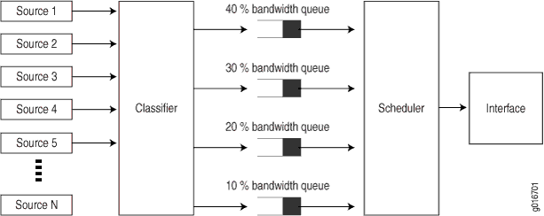
Figure 2 shows the packet flow through the CoS components that you can configure.
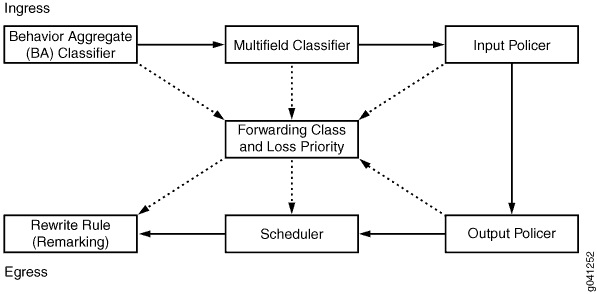
The middle box (Forwarding Class and Loss Priority) represents two values that you can use on ingress and egress interfaces. The system uses these values for classifying traffic on ingress interfaces and for rewrite rule re-marking on egress interfaces. Each outer box represents a process component. The components in the top row apply to incoming packets. The components in the bottom row apply to outgoing packets.
The solid-line arrows show the direction of packet flow from ingress to egress. The dotted-line arrows that point to the forwarding class and loss priority box indicate processes that configure (set) the forwarding class and loss priority. The dotted-line arrows that point away from the forwarding class and loss priority box indicate processes that use forwarding class and loss priority as input values on which to base actions.
For example, the BA classifier sets the forwarding class and loss priority of incoming packets, so the forwarding class and loss priority are outputs of the classifier and the arrow points away from the classifier. The scheduler receives the forwarding class and loss priority settings, and queues the outgoing packets based on those settings, so the arrow points toward the scheduler.