ON THIS PAGE
Example: Configure Centralized Clocking on the Enhanced MX Switch Control Board
These examples show how to configure the following clock sources and features on an Enhanced MX Switch Control Board (SCBE).
These examples show how to configure the following clock sources and features on an Enhanced MX Switch Control Board (SCBE): Synchronous Ethernet, ordinary Precision Time Protocol (PTP) timeReceiver, hybrid PTP timeReceiver, and retiming through the building-integrated timing supply (BITS) external interface.
Requirements
These examples use the following hardware and software components:
-
One MX240, MX480, or MX960 router with MPC 16x10GE or MPC2Es (see MPCs Supported by MX Series Routers) for Synchronous Ethernet clock sources, or MPC2E-P for PTP clock sources
-
One Synchronous Ethernet clock source device (may be an MX240, MX480, or MX960 router)
-
One PTP grandmaster clock device
-
One BITS device (may be the same as the PTP grandmaster clock device)
-
Junos OS Release 12.2 or later for MX240, MX480, or MX960 routers
-
Junos OS Release 12.3 or later to configure a BITS interface as an input, output, or I/O clock source for MX240, MX480, or MX960 routers
Before you begin configuring centralized clocking on an interface that uses Synchronous Ethernet, ensure that you have configured the MX Series interface as a chassis synchronization source to the device that provides a Synchronous Ethernet clock source.
-
Configure the MX Series interface as a chassis synchronization source to the device that provides a Synchronous Ethernet clock source.
Overview
With the addition of a Stratum 3 clock module to the SCBE, an MX240, MX480, or MX960 chassis can perform clock monitoring, filtering, and holdover in a centralized chassis location. Chassis line cards can be configured to recover network timing clocks at the physical layer via Synchronous Ethernet or by a packet-based PTP implementation. These recovered clocks are routed to the SCBE Stratum 3 clock module via the chassis backplane. A clock selection algorithm is run that selects the best quality recovered clock from the list of configured clock sources. The Stratum 3 clock module locks to the selected clock source and fans it out to the chassis line cards. 16x10GE 3D and MPC2Es (see MPCs Supported by MX Series Routers) can distribute this clock to downstream network elements via Synchronous Ethernet.
The Stratum 3 clock module acquires holdover data while locked to the selected clock source. If the clock fails, the Stratum 3 clock module enters holdover mode and replays collected holdover data to maintain its output clock. The Stratum 3 holdover performance depends on the drift of the SCBE OCXO device.
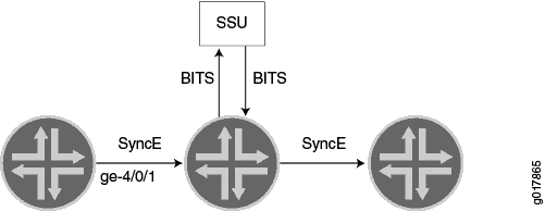
In Junos 12.3, support was added for synchronizing an MX240, MX480, or MX960 chassis with an SCBE to a BITS timing source through an RJ-48 port on the SCBE. The BITS external clock interface supports the sending and receiving of Synchronization Status Message (SSM) quality levels. The quality level is used by the chassis clock-selection algorithm. When BITS output is configured, the source-mode default is the selected line clock source.
The BITS external interface can be connected to a retiming device, which cleans up the
clock and sends it back in the external BITS interface. The conditioned input BITS clock is
selected as the chassis clock and distributed downstream via Synchronous Ethernet
interfaces. The tx-dnu-to-line-source-enable option is used to prevent a
timing loop. Figure 1 shows the BITS
retiming functionality using a Synchronization Supply Unit (SSU). For instructions on how to
configure retiming through the BITS external interface, see Configure Retiming through the BITS External Interface.
Prior to the SCBE, clock monitoring, filtering, and holdover functions were distributed throughout the chassis and performed on MPC2E line cards. This distributed clocking mode limits the distribution of timing to downstream network elements on MPC2E interfaces only. Centralized clocking mode removes this limitation by supporting the distribution of timing on MPC 16x 10GE line interfaces as well.
Configuration
To configure centralized clocking, perform one or more of these tasks:
- Configure Centralized Clocking from a Synchronous Ethernet Clock Source
- Configure Centralized Clocking from an Ordinary PTP Clock Source
- Configure Centralized Clocking from a Hybrid PTP Clock Source
- Configure Retiming through the BITS External Interface
Configure Centralized Clocking from a Synchronous Ethernet Clock Source
CLI Quick Configuration
To quickly configure this example, copy the following commands, paste them into a text
file, remove any line breaks, change any details necessary to match your network
configuration, and then copy and paste the commands into the CLI at the
[edit] hierarchy level.
set chassis synchronization network-option option-2
set chassis synchronization source interfaces ge-4/1/0 priority 1
set chassis synchronization source interfaces ge-4/1/0 quality-level st3
Step-by-Step Procedure
The following example requires you to navigate various levels in the configuration hierarchy. For instructions on how to do that, see Using the CLI Editor in Configuration Mode in the CLI User Guide.
To configure a Synchronous Ethernet clock source:
-
Configure the network option:
[edit chassis synchronization]
user@host# set network-option option-2
-
Configure the priority and quality level of the clock source on this interface:
[edit chassis synchronization source interfaces ge-4/1/0]
user@host# set priority 1
user@host# set quality-level st3
Results
From configuration mode, confirm your configuration by entering the show
chassis synchronization command. If the output does not display the intended
configuration, repeat the configuration instructions in this example to correct it.
[edit]
user@host# show chassis synchronization
network-option option-2;
source {
     interfaces ge-4/1/0 {
          priority 1;
          quality-level st3;
     }
}
After you configure the device, enter commit from configuration
mode.
Configure Centralized Clocking from an Ordinary PTP Clock Source
Step-by-Step Procedure
To configure a PTP clock source:
-
Configure ordinary mode PTP on the ge-4/1/9 interface to the PTP grandmaster clock device. See Example: Configure Precision Time Protocol.
Configure Centralized Clocking from a Hybrid PTP Clock Source
CLI Quick Configuration
To quickly configure this example, copy the following commands, paste them into a text
file, remove any line breaks, change any details necessary to match your network
configuration, and then copy and paste the commands into the CLI at the
[edit] hierarchy level.
set chassis synchronization network-option option-2
set chassis synchronization source interfaces ge-4/1/0 priority 1
set chassis synchronization source interfaces ge-4/1/0 quality-level st3
Step-by-Step Procedure
The following example requires you to navigate various levels in the configuration hierarchy. For instructions on how to do that, see Using the CLI Editor in Configuration Mode in the CLI User Guide.
To configure a hybrid PTP clock source:
-
Configure the network option:
[edit chassis synchronization]
user@host# set network-option option-2
-
Configure the priority and quality level of the clock source on this interface:
[edit chassis synchronization source interfaces ge-4/1/0]
user@host# set priority 1
user@host# set quality-level st3
-
Configure hybrid mode PTP on the ge-4/1/9 interface to the PTP grandmaster clock device. For the
synchronous-ethernet-mappinginterface, specify the Synchronous Ethernet interface used in Step 2.
Results
From configuration mode, confirm your configuration by entering the show
chassis synchronization command. If the output does not display the intended
configuration, repeat the configuration instructions in this example to correct it.
[edit]
user@host# show chassis synchronization
network-option option-2;
source {
     interfaces ge-4/1/0 {
          priority 1;
          quality-level st3;
     }
}
After you configure the device, enter commit from configuration
mode.
Configure Retiming through the BITS External Interface
CLI Quick Configuration
To quickly configure this example, copy the following commands, paste them into a text
file, remove any line breaks, change any details necessary to match your network
configuration, and then copy and paste the commands into the CLI at the
[edit] hierarchy level.
set chassis synchronization network-option option-2
set chassis synchronization interfaces external signal-type t1
set chassis synchronization interfaces external t1-options line-encoding b8zs
set chassis synchronization interfaces external t1-options framing sf
set chassis synchronization output interfaces external wander-filter-disable
set chassis synchronization output interfaces external holdover-mode-disable
set chassis synchronization output interfaces external source-mode line
set chassis synchronization output interfaces external tx-dnu-to-line-source-enable
set chassis synchronization output interfaces external minimum-quality st3
set chassis synchronization source interfaces ge-4/0/1 quality-level st3
set chassis synchronization source interfaces external quality-level prs
Step-by-Step Procedure
The following example requires you to navigate various levels in the configuration hierarchy. For instructions on how to do that, see Using the CLI Editor in Configuration Mode in the CLI User Guide.
To configure retiming through the BITS external interface using an SSU:
-
Configure the network option (G.812 type IV clock):
[edit chassis synchronization]
user@host# set network-option option-2
-
Configure the external BITS signal type (T1-coded 1.544-MHz signal on 100-ohm balanced line):
[edit chassis synchronization interfaces external]
set signal-type t1
-
Configure the external BITS signal line-encoding (B8ZS) and framing (superframe) options:
[edit chassis synchronization interfaces external]
user@host# set t1-options line-encoding b8zs
user@host# set t1-options framing sf
-
Configure the output external BITS signal properties:
-
Disable wander filtering:
[edit chassis synchronization output interfaces external]
user@host# set wander-filter-disable
-
Disable holdover:
[edit chassis synchronization output interfaces external]
user@host# set holdover-mode-disable
-
Select the best line clock source for output:
[edit chassis synchronization output interfaces external]
user@host# set source-mode line
-
Set Tx QL to DNU/DUS on the line source interface to prevent a timing loop:
[edit chassis synchronization output interfaces external]
user@host# set tx-dnu-to-line-source-enable
-
Set minimum quality level:
[edit chassis synchronization output interfaces external]
user@host# set minimum-quality st3
-
-
Configure the incoming clock source and quality level:
[edit chassis synchronization source interfaces ge-4/0/1]
user@host# set quality-level st3
-
Configure the external clock source and quality level:
[edit chassis synchronization source interfaces external]
user@host# set quality-level prs
Results
From configuration mode, confirm your configuration by entering the show
chassis synchronization command. If the output does not display the intended
configuration, repeat the configuration instructions in this example to correct it.
[edit]
user@host# show chassis synchronization
network-option option-2;
interfaces external {
    signal-type t1;
    t1-options {
        line-encoding b8zs;
        framing sf;
    }
}
output {
    interfaces external {
        wander-filter-disable;
        holdover-mode-disable;
        source-mode line;
        tx-dnu-to-line-source-enable;
        minimum-quality st3;
    }
}
source {
    interfaces ge-4/0/1 {
        quality-level st3;
    }
    interfaces external {
        quality-level prs;
    }
}
After you configure the device, enter commit from configuration
mode.
Verification
Confirm that the configuration is working properly.
- Verify the Synchronous Ethernet Clock Source
- Verify the Ordinary PTP Clock Source
- Verify the Hybrid PTP Clock Source
- Verify the Retiming through the BITS External Interface
Verify the Synchronous Ethernet Clock Source
Purpose
Verify that the MX Series router recovers, selects, qualifies, and locks to the configured Synchronous Ethernet clock source.
Action
From operational mode, enter the show chassis synchronization
clock-module command.
user@host> show chassis synchronization clock-module

Clock module on SCB0
  Current role     : master
  Current state    : locked to ge-4/1/0
    State for      : 0 days, 00 hrs, 00 mins, 15 secs
    State since    : Mon Jun  6 07:28:47 2011
  Monitored clock sources
    Interface      Type         Status
    ge-4/1/0       syncE        qualified-selected
Meaning
The Monitored clock sources field shows that the ge-4/1/0 interface has the Synchronous Ethernet type and is the qualified and selected centralized clock source.
Verify the Ordinary PTP Clock Source
Purpose
Verify that the MX Series router recovers, selects, qualifies, and locks to the configured PTP clock source.
Action
From operational mode, enter the show chassis synchronization
clock-module command.
user@host> show chassis synchronization clock-module

Clock module on SCB0
  Current role     : master
  Current state    : locked to ge-4/1/9
    State for      : 0 days, 00 hrs, 00 mins, 45 secs
    State since    : Wed Jun 29 10:52:05 2011
  Monitored clock sources
    Interface      Type         Status
    ge-4/1/9       ptp          qualified-selected
Meaning
The Monitored clock sources field shows that the ge-4/1/9 interface has the ptp type and is the qualified and selected centralized clock source.
Verify the Hybrid PTP Clock Source
Purpose
Verify that the MX Series router recovers, selects, qualifies, and locks to the configured hybrid PTP clock source.
Action
From operational mode, enter the show chassis synchronization
clock-module command.
user@host> show chassis synchronization clock-module

Clock module on SCB0
  Current role     : master
  Current state    : locked to ge-4/1/9
    State for      : 0 days, 00 hrs, 00 mins, 15 secs
    State since    : Wed Jun 29 11:19:25 2011
  Monitored clock sources
    Interface      Type         Status
    ge-4/1/9       ptp-hybrid   qualified-selected

Configured sources:

Interface           : ge-4/1/0
Status              : Primary       Index       : 218
Clock source state  : Clk qualified Priority    : 1
Configured QL       : ST3           ESMC QL     : DUS
Clock source type   : ifd           Clock Event : Clock locked
Kernel flags        : Up,sec,
Meaning
The Monitored clock sources field shows that the ge-4/1/9 interface has the ptp-hybrid type and is the qualified and selected centralized clock source. The Configured sources field shows that the ge-4/1/0 interface has the Clock locked Clock Event .
Verify the Retiming through the BITS External Interface
Purpose
Verify that the MX Series router recovers, selects, qualifies, and locks to the configured clock source, and that the external clock is locked to the configured clock source.
Action
From operational mode, enter the show chassis synchronization
extensive command.
user@host> show chassis synchronization extensive

Current clock status  : Locked
Clock locked to       : Primary

Configured interfaces:

Name         : external
Signal type  : t1 (sf b8zs)
Rx status    : active
Tx status    : active
LED color    : green

Configured outputs:

Interface      : external
Tx status      : active
Minimum QL     : ST3             Tx QL         : ST3
Holdover mode  : disabled        Wander filter : disabled
Source mode    : line            Source Tx DNU : enabled
Holdover data  : valid
Current state  : locked to ge-4/0/1
  State for    : 0 days, 00 hrs, 24 mins, 47 secs
  State since  : Thu Sep  6 13:01:07 2012

Configured sources:

Interface           : external
Status              : Primary       Index       : 0
Clock source state  : Clk qualified Priority    : Default(6)
Configured QL       : PRS           ESMC QL     : PRS
Clock source type   : extern        Clock Event : Clock locked
Interface State     : Up,pri,

Interface           : ge-4/0/1
Status              : Secondary     Index       : 152
Clock source state  : Clk qualified Priority    : Default(8)
Configured QL       : ST3           ESMC QL     : DUS
Clock source type   : ifd           Clock Event : Clock qualified
Interface State     : Up,sec,ESMC TX(QL DUS/SSM 0xf),
Meaning
The Configured interfaces field shows that the external interface receive and transmit statuses are active. The Configured outputs field shows that the current state is locked to ge-4/0/1. The Configured sources field shows that the external interface is the qualified and selected centralized clock source, and has the Clock locked Clock Event. The Configured sources field shows that the ge-4/0/1 interface is the secondary clock source, and has the Clock qualified Clock Event.