Help us improve your experience.

Let us know what you think.

Do you have time for a two-minute survey?


Centralized Clocking

SUMMARY Centralized Clocking is an internal clock synchronization approach where clocks of system are synchronized with one of clock of system.

Centralized Clocking Overview

The Enhanced SCB SCBE and the Enhanced SCB SCBE2 on the MX240, MX480, and MX960 routers support a Stratum 3 clock module that functions as a centralized point within the chassis for clock monitoring, filtering, holdover, and selection.

The Stratum 3 clock module produces a 19.44 MHz clock that is locked to a chassis synchronization clock source that is configured with the highest quality. The chassis clock signals are transmitted through the backplane to all the MPCs. The MPCs route the clock signals to their MICs, where the clock signals are driven out on all line interfaces thereby allowing the timing information to be distributed to the downstream routers.

You can configure external and line input synchronization sources at the [edit chassis synchronization output] hierarchy level, at the [edit chassis synchronization source interfaces] hierarchy level, and at the [edit chassis synchronization interfaces] hierarchy level, that become candidates to be selected by the chassis’s clock selection algorithm. The clock selection algorithm selects the highest-quality candidate clock source, which is then used as the chassis’s synchronization source.

The external clock interface on SCBE allows the building-integrated timing supply (BITS) clock source or the clock signals received from the global positioning system (GPS) receiver to act as an input clock source to the centralized timing circuit, or allows the centralized timing signals to act as an output clock source to the BITS source or to the GPS receiver.

The centralized mode is applicable to mobile backhaul infrastructures and for network transition from traditional TDM to Ethernet network elements with the support of Synchronous Ethernet.

Points to Remember

The following are the points to remember about centralized clocking:

  • Before you begin configuring centralized clocking on an interface that uses Synchronous Ethernet, ensure that you have configured the interface as a chassis synchronization source to the router that provides a Synchronous Ethernet clock source.

  • Before you remove the SCBE from the router, you must delete the configuration under the [edit chassis synchronization] hierarchy. Similarly, before you remove the SCBE2 from the router, you must delete the configuration under the [edit chassis synchronization] hierarchy.

  • On SCBE2, the external-0/0 interface is located on SCB0 and the external-1/0 interface is located on SCB1.

    When you configure the external clock interface for input, the BITS or GPS clock source—the source depends on how you configure the interface—sends the synchronized input clock signals to the centralized timing circuit in the SCBE. When you configure the external clock interface for output, the centralized timing circuit sends out the synchronized clock signal—BITS or GPS—to be transmitted to the downstream routers.

    For more information about SCBE hardware, see SCBE2-MX Description and SCBE2-MX LEDs.

The following sections explain centralized clocking and its features in detail:

Note:

Hereafter, all features that are explained for SCBE are also applicable for SCBE2 unless otherwise specified.

Stratum 3 Clock Module

SCBE has a Stratum 3 centralized clock module that takes in synchronization sources on its reference input pins. When instructed by the clock selection algorithm, the clock module selects one of the reference inputs to lock its 19.44 MHz output clock. The MPCs select the chassis clock from the active SCBE to use it as a clock for their interface transmitters, thereby allowing the downstream routers to recover and synchronize to the chassis clock. A 20 MHz oscillator provides Stratum 3 free-run and holdover quality.

The clock module does not perform any automatic switching between the reference clocks, rather when Junos OS detects the loss of signal or clock, frequency inaccuracy, or phase irregularities, the clock module runs a clock selection algorithm and switches to the next highest-quality input reference.

The Stratum 3 clock modules—on the primary and the backup SCBE—are cross-wired to eliminate any phase transients during SCBE switchover. The backup SCBE locks to the primary’s Stratum 3 clock module.

BITS and GPS Support

Table 1 maps the Junos OS Release with the feature release of BITS and GPS on SCBE and SCBE2:

Table 1: BITS and GPS Support on SCBE and SCBE2

Feature

Switch Control Board

Junos OS Release

BITS

SCBE

12.3

GPS

SCBE

13.3

BITS

SCBE2

13.3

External Clock Interface Input

BITS and GPS can be configured on the external clock interface on the SCBE.

The following sections explain external clock interface input for BITS and GPS:

External Clock Interface Input for BITS

When the BITS clock is qualified by the Stratum 3 clock module, it becomes a candidate clock source to the clock selection algorithm. BITS can simultaneously support both input and output clocking.

The external clock interface for BITS can recover:

  • A framed 1.544 Mbps (T1) clock or a framed 2.048 Mbps (E1) clock. The T1/E1 framer supports sending and receiving of SSM quality levels through SA bits.

  • An unframed 2048 kHz (G.703 T12) clock. You must configure an input SSM quality level when the external clock interface is configured for a signal type that does not support SSM, such as an unframed 2048 kHz (T12) clock, or a T1 superframe (T1 SF) clock.

On T1/T12 interfaces that do not support SSM, you must configure the SSM quality levels. On E1 interfaces, the Sa bits receive and transmit the SSM quality level.

MX10003 and MX204 routers support T1/E1 framed and 2.048MHz unframed clock input.

External Clock Interface Input for GPS

The GPS external clock interface supports:

  • 1 MHz, 5 MHz, and 10 MHz frequencies.

  • Pulse per second (PPS) signals on BNC connectors—a special cable converts signals between the BNC connector and the RJ–45 port. These signals are fed into the Stratum  3 centralized clock module for qualification and monitoring. After qualification, the GPS source becomes a valid chassis clock source candidate.

  • Time of day (TOD) over a serial link. Most GPS source TOD string formats are supported by Junos OS, thereby enabling you to configure a generic TOD format string. This format tells the Routing Engine how to interpret the incoming TOD character string.

You must also configure an input SSM quality level value, where the quality level is used by the chassis clock selection algorithm when the quality level mode is enabled.

For the GPS receiver to be qualified as a clock source, the frequency and the PPS signal from it must be qualified by the SCBE Stratum 3 module. The SCBE is synchronized with the GPS source TOD.

The 10MHz frequency and PPS are supported by an RJ–45 connector for SCBE/SCBE2. Figure 1 illustrates the actual pinout of the connector.
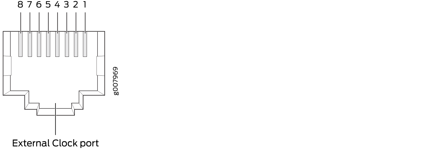
Figure 1: RJ–45 Connector for SCBE/SCBE2RJ–45 Connector for SCBE/SCBE2
Table 2: RJ–45 Connector Pinout Information for SBE/SCBE2

Pin

Signal

1

RX

2

RX

3

1 PPS GND

4

TX

5

TX

6

10 MHz GND

7

1 PPS

8

10 MHz

Note that the GPS receiver is configured to support 10 MHz, 1 PPS, and TOD by default when it acts as a primary reference time clock.

MX10003 router supports one GPS port per SPM which can be configured with 1MHz, 5MHz, and 10MHz frequencies and 1PPS signal.

MX204 router supports GPS with 1MHz, 5MHz, and 10MHz frequencies and 1PPS signal.

External Clock Interface Output

The external clock interface can be configured to drive BITS or GPS timing output (GPS timing output for frequency and PPS signal only). The BITS or GPS output is configured to select the output clock source but in the absence of an output configuration, the BITS or the GPS output is disabled. When the external clock interface is configured for output, it selects the clock source on the basis of the configured source mode.

The external clock interface can be configured to drive BITS timing output. When the external clock interface is configured as a BITS timing output, the following scenarios occur:

  • The external clock interface drives the BITS timing output.

    The chassis clock or the line clock are used as the source on the basis of the source mode configuration.

    The best—configured—line source is transmitted out the BITS interface, when the output source-mode statement is configured as line.

    The central clock module is set to holdover and the output is suppressed when the BITS output is configured and there are no valid clock sources available.

G.703 2.048MHz Signal Type for BITS Interfaces

The ITU-T Recommendation G.703, Physical/electrical characteristics of hierarchical digital interfaces, is a standard method for encoding clock and data signals into a single signal. This signal is then used to synchronize various data communications devices, such as switches, routers and multiplexers at a data rate of 2.048 MHz. Both directions of the G.703 signal must use the same signal type. To configure signal type parameters for a building-integrated timing supply (BITS) interface, include the following statements at the [edit chassis synchronization ] hierarchy level:

Redundancy

On SCBE, the primary and the secondary SCBs monitor their respective clock sources, and the external clock interface source is accessible only to its local clocking hardware. Therefore, the clock signals cannot be routed between the primary and the secondary SCB. Redundancy is achieved after a Routing Engine switchover. When a switchover occurs, the new primary SCB reruns the clock selection algorithm after the configured switchover time expires to select a new clock source.

On SCBE2, simultaneous BITS/BITS redundancy can be achieved because the external interfaces for BITS on the primary SCB and the secondary SCB are wired. Note that BITS redundancy is achieved without a Routing Engine switchover on SCBE2.

The following scenarios are supported for BITS/BITS redundancy:

  • You can configure both the external interfaces for BITS input as reference clocks. Therefore, on the basis of the configured clock quality, one of the BITS inputs is considered as a primary clock source and the other as a secondary clock source.

  • When the signal from the primary BITS input stops or degrades, the secondary BITS input takes over as primary, thereby providing redundancy across BITS interfaces.

GRES is supported on MX240, MX480, and MX960 routers with SCBE2.

Example: Configure Centralized Clocking on MX2020

These examples show how to configure the following clock sources and features on an MX2020 router: Synchronous Ethernet, Precision Time Protocol (PTP) client, hybrid PTP client, and retiming through the building-integrated timing supply (BITS) external interface.

Requirements

These examples use the following hardware and software components:

  • One MX2020, with MPC 16x10GE or MPC2Es (see MPCs Supported by MX Series Routers) for Synchronous Ethernet clock sources, or MPC2E-P for PTP clock sources

  • One Synchronous Ethernet clock source device

  • One PTP reference clock device

  • One BITS device (may be the same as the PTP reference clock device)

  • Junos OS Release 13.3 for MX2020 routers

  • Junos OS Release 13.3 or later to configure a BITS interface as an input, output, or I/O clock source for MX2020 router

  • Configure the MX Series interface as a chassis synchronization source to the device that provides a Synchronous Ethernet clock source.

Overview

With the addition of a Stratum 3 (ST3) clock module the MX2020 chassis can perform clock monitoring, filtering, and holdover in a centralized chassis location. Chassis line cards can be configured to recover network timing clocks at the physical layer via Synchronous Ethernet or by a packet-based PTP implementation. These recovered clocks are routed to MX2020 SCB ST3 clock module via the chassis backplane. A clock selection algorithm is run that selects the best quality recovered clock from the list of configured clock sources. The ST3 clock module locks to the selected clock source and fans it out to the chassis line cards. 16x10GE 3D and MPC2Es (see MPCs Supported by MX Series Routers) can distribute this clock to downstream network elements via Synchronous Ethernet.

The ST3 clock module acquires holdover data while locked to the selected clock source. If the clock fails, the ST3 clock module enters holdover mode and replays collected holdover data to maintain its output clock. The ST3 holdover performance depends on the drift of the MX SCB OCXO device.

In Junos 13.3, support was added for synchronizing an MX2020 chassis to a BITS timing source using any of the two BITS interfaces. The quality level is used by the chassis clock-selection algorithm. When BITS output is configured, the source-mode can be configured as either chassis or line.

The BITS external interface can be connected to a retiming device, which cleans up the clock and sends it back in the external BITS interface. The conditioned input BITS clock is selected as the chassis clock and distributed downstream via Synchronous Ethernet interfaces. The tx-dnu-to-line-source-enable option is used to prevent a timing loop. For instructions on how to configure retiming through the BITS external interface, see Configure Retiming through the BITS External Interface.

Prior to 13.3, clock monitoring, filtering, and holdover functions were distributed throughout the chassis and performed on MPC2E line cards. This distributed clocking mode limits the distribution of timing to downstream network elements on MPC2E interfaces only. Centralized clocking mode removes this limitation by supporting the distribution of timing on MPC 16x 10GE line interfaces as well.

Configuration

To configure centralized clocking, perform one or more of these tasks:

Configure Centralized Clocking from a Synchronous Ethernet Clock Source

CLI Quick Configuration

To quickly configure this example, copy the following commands, paste them into a text file, remove any line breaks, change any details necessary to match your network configuration, and then copy and paste the commands into the CLI at the [edit] hierarchy level.

Step-by-Step Procedure

The following example requires you to navigate various levels in the configuration hierarchy. For instructions on how to do that, see Using the CLI Editor in Configuration Mode in the CLI User Guide.

To configure a Synchronous Ethernet clock source:

  1. Configure the network option:

  2. Configure the priority and quality level of the clock source on this interface:

Results

From configuration mode, confirm your configuration by entering the show chassis synchronization command. If the output does not display the intended configuration, repeat the configuration instructions in this example to correct it.

After you configure the device, enter commit from configuration mode.

Configure an Ordinary PTP Clock Source

Step-by-Step Procedure

To configure a PTP clock source:

  1. Configure ordinary mode PTP on the ge-4/1/9 interface to the PTP reference clock device. See Example: Configure Precision Time Protocol.

Configure Centralized Clocking from a Hybrid Mode PTP Clock Source

CLI Quick Configuration

To quickly configure this example, copy the following commands, paste them into a text file, remove any line breaks, change any details necessary to match your network configuration, and then copy and paste the commands into the CLI at the [edit] hierarchy level.

Step-by-Step Procedure

The following example requires you to navigate various levels in the configuration hierarchy. For instructions on how to do that, see Using the CLI Editor in Configuration Mode in the CLI User Guide.

To configure a hybrid mode PTP clock source:

  1. Configure the network option:

  2. Configure the priority and quality level of the clock source on this interface:

  3. To configure hybrid mode PTP on the ge-4/1/9 interface to the PTP reference clock device, see Configure Hybrid Mode PTP.

Results

From configuration mode, confirm your configuration by entering the show chassis synchronization command. If the output does not display the intended configuration, repeat the configuration instructions in this example to correct it.

After you configure the device, enter commit from configuration mode.

Configure Hybrid Mode PTP

CLI Quick Configuration

To quickly configure hybrid mode on the ge-4/1/0 interface with the clock source IP address as 2.2.2.2, copy the following commands, paste them in a text file, remove any line breaks, and then copy and paste the commands into the CLI.

[edit]

set protocols ptp slave hybridset protocols ptp slave hybrid synchronous-ethernet-mappingset protocols ptp slave hybrid synchronous-ethernet-mapping clock-source 2.2.2.2 interface ge-4/1/0set protocols ptp slave convert-clock-class-to-quality-level

Step-by-Step Procedure

To configure hybrid mode on an MX240 router with mapping of the PTP clock class perform the following steps:

  1. Configure the convert-clock-class-to-quality-level option on the client at the [edit protocols ptp slave] hierarchy level.

  2. Configure hybrid mode on the client.

  3. Configure the Synchronous Ethernet mapping option, IP address of the primary clock as 2.2.2.2, and the interface ge-4/1/0 for hybrid mode on the client.

Results

Display the results of the configuration of hybrid mode with the mapping of the PTP clock class to the ESMC quality level:

Configure Retiming through the BITS External Interface

CLI Quick Configuration

To quickly configure this example, copy the following commands, paste them into a text file, remove any line breaks, change any details necessary to match your network configuration, and then copy and paste the commands into the CLI at the [edit] hierarchy level.

Step-by-Step Procedure

The following example requires you to navigate various levels in the configuration hierarchy. For instructions on how to do that, see Using the CLI Editor in Configuration Mode in the CLI User Guide.

To configure retiming through the BITS external interface using an SSU:

  1. Configure the network option (G.812 type IV clock):

  2. Configure the external BITS signal type (T1-coded 1.544-MHz signal on 100-ohm balanced line):

  3. Configure the external BITS signal line-encoding (B8ZS) and framing (superframe) options:

  4. Configure the output external BITS signal properties:

    • Disable wander filtering:

    • Disable holdover:

    • Select the best line clock source for output:

    • Set Tx QL to DNU/DUS on the line source interface to prevent a timing loop:

    • Set minimum quality level:

  5. Configure the incoming clock source and quality level:

  6. Configure the external clock source and quality level:

Results

From configuration mode, confirm your configuration by entering the show chassis synchronization command. If the output does not display the intended configuration, repeat the configuration instructions in this example to correct it.

After you configure the device, enter commit from configuration mode.

Verification

Confirm that the configuration is working properly.

Verify the Synchronous Ethernet Clock Source

Purpose

Verify that the MX Series router recovers, selects, qualifies, and locks to the configured Synchronous Ethernet clock source.

Action

From operational mode, enter the show chassis synchronization clock-module command.

Meaning

The Monitored clock sources field shows that the ge-4/1/0 interface has the Synchronous Ethernet type and is the qualified and selected centralized clock source.

Verify the Ordinary PTP Clock Source

Purpose

Verify that the MX Series router recovers, selects, qualifies, and locks to the configured PTP clock source.

Action

From operational mode, enter the show chassis synchronization clock-module command.

Meaning

The Monitored clock sources field shows that the ge-4/1/9 interface has the ptp type and is the qualified and selected centralized clock source.

Verify the Hybrid PTP Clock Source

Purpose

Verify that the MX Series router recovers, selects, qualifies, and locks to the configured hybrid PTP clock source.

Action

From operational mode, enter the show chassis synchronization clock-module command.

Meaning

The Monitored clock sources field shows that the ge-4/1/9 interface has the ptp-hybrid type and is the qualified and selected centralized clock source. The Configured sources field shows that the ge-4/1/0 interface has the Clock locked Clock Event .

Verify the Retiming through the BITS External Interface

Purpose

Verify that the MX Series router recovers, selects, qualifies, and locks to the configured clock source, and that the external clock is locked to the configured clock source.

Action

From operational mode, enter the show chassis synchronization extensive command.

Meaning

The Configured interfaces field shows that the external interface receive and transmit statuses are active. The Configured outputs field shows that the current state is locked to ge-4/0/1. The Configured sources field shows that the external interface is the qualified and selected centralized clock source, and has the Clock locked Clock Event. The Configured sources field shows that the ge-4/0/1 interface is the secondary clock source, and has the Clock qualified Clock Event.

Example: Configure Centralized Clocking on the Enhanced MX Switch Control Board

These examples show how to configure the following clock sources and features on an Enhanced MX Switch Control Board (SCBE): Synchronous Ethernet, ordinary Precision Time Protocol (PTP) client, hybrid PTP client, and retiming through the building-integrated timing supply (BITS) external interface.

Requirements

These examples use the following hardware and software components:

  • One MX240, MX480, or MX960 router with MPC 16x10GE or MPC2Es (see MPCs Supported by MX Series Routers) for Synchronous Ethernet clock sources, or MPC2E-P for PTP clock sources

  • One Synchronous Ethernet clock source device (may be an MX240, MX480, or MX960 router)

  • One PTP reference clock device

  • One BITS device (may be the same as the PTP reference clock device)

  • Junos OS Release 12.2 or later for MX240, MX480, or MX960 routers

  • Junos OS Release 12.3 or later to configure a BITS interface as an input, output, or I/O clock source for MX240, MX480, or MX960 routers

Before you begin configuring centralized clocking on an interface that uses Synchronous Ethernet, ensure that you have configured the MX Series interface as a chassis synchronization source to the device that provides a Synchronous Ethernet clock source.

  • Configure the MX Series interface as a chassis synchronization source to the device that provides a Synchronous Ethernet clock source.

Overview

With the addition of a Stratum 3 clock module to the SCBE, an MX240, MX480, or MX960 chassis can perform clock monitoring, filtering, and holdover in a centralized chassis location. Chassis line cards can be configured to recover network timing clocks at the physical layer via Synchronous Ethernet or by a packet-based PTP implementation. These recovered clocks are routed to the SCBE Stratum 3 clock module via the chassis backplane. A clock selection algorithm is run that selects the best quality recovered clock from the list of configured clock sources. The Stratum 3 clock module locks to the selected clock source and fans it out to the chassis line cards. 16x10GE 3D and MPC2Es (see MPCs Supported by MX Series Routers) can distribute this clock to downstream network elements via Synchronous Ethernet.

The Stratum 3 clock module acquires holdover data while locked to the selected clock source. If the clock fails, the Stratum 3 clock module enters holdover mode and replays collected holdover data to maintain its output clock. The Stratum 3 holdover performance depends on the drift of the SCBE OCXO device.

In Junos 12.3, support was added for synchronizing an MX240, MX480, or MX960 chassis with an SCBE to a BITS timing source through an RJ-48 port on the SCBE. The BITS external clock interface supports the sending and receiving of Synchronization Status Message (SSM) quality levels. The quality level is used by the chassis clock-selection algorithm. When BITS output is configured, the source-mode default is the selected line clock source.

The BITS external interface can be connected to a retiming device, which cleans up the clock and sends it back in the external BITS interface. The conditioned input BITS clock is selected as the chassis clock and distributed downstream via Synchronous Ethernet interfaces. The tx-dnu-to-line-source-enable option is used to prevent a timing loop. Figure 1 shows the BITS retiming functionality using a Synchronization Supply Unit (SSU). For instructions on how to configure retiming through the BITS external interface, see Configure Retiming through the BITS External Interface.

Figure 2: BITS Retiming with Synchronization Supply Unit (SSU)BITS Retiming with Synchronization Supply Unit (SSU)

Prior to the SCBE, clock monitoring, filtering, and holdover functions were distributed throughout the chassis and performed on MPC2E line cards. This distributed clocking mode limits the distribution of timing to downstream network elements on MPC2E interfaces only. Centralized clocking mode removes this limitation by supporting the distribution of timing on MPC 16x 10GE line interfaces as well.

Configuration

To configure centralized clocking, perform one or more of these tasks:

Configure Centralized Clocking from a Synchronous Ethernet Clock Source

CLI Quick Configuration

To quickly configure this example, copy the following commands, paste them into a text file, remove any line breaks, change any details necessary to match your network configuration, and then copy and paste the commands into the CLI at the [edit] hierarchy level.

Step-by-Step Procedure

The following example requires you to navigate various levels in the configuration hierarchy. For instructions on how to do that, see Using the CLI Editor in Configuration Mode in the CLI User Guide.

To configure a Synchronous Ethernet clock source:

  1. Configure the network option:

  2. Configure the priority and quality level of the clock source on this interface:

Results

From configuration mode, confirm your configuration by entering the show chassis synchronization command. If the output does not display the intended configuration, repeat the configuration instructions in this example to correct it.

After you configure the device, enter commit from configuration mode.

Configure Centralized Clocking from an Ordinary PTP Clock Source

Step-by-Step Procedure

To configure a PTP clock source:

  1. Configure ordinary mode PTP on the ge-4/1/9 interface to the PTP reference clock device. See Example: Configure Precision Time Protocol.

Configure Centralized Clocking from a Hybrid PTP Clock Source

CLI Quick Configuration

To quickly configure this example, copy the following commands, paste them into a text file, remove any line breaks, change any details necessary to match your network configuration, and then copy and paste the commands into the CLI at the [edit] hierarchy level.

Step-by-Step Procedure

The following example requires you to navigate various levels in the configuration hierarchy. For instructions on how to do that, see Using the CLI Editor in Configuration Mode in the CLI User Guide.

To configure a hybrid PTP clock source:

  1. Configure the network option:

  2. Configure the priority and quality level of the clock source on this interface:

  3. Configure hybrid mode PTP on the ge-4/1/9 interface to the PTP reference clock device. For the synchronous-ethernet-mapping interface, specify the Synchronous Ethernet interface used in Step 2.

Results

From configuration mode, confirm your configuration by entering the show chassis synchronization command. If the output does not display the intended configuration, repeat the configuration instructions in this example to correct it.

After you configure the device, enter commit from configuration mode.

Configure Retiming through the BITS External Interface

CLI Quick Configuration

To quickly configure this example, copy the following commands, paste them into a text file, remove any line breaks, change any details necessary to match your network configuration, and then copy and paste the commands into the CLI at the [edit] hierarchy level.

Step-by-Step Procedure

The following example requires you to navigate various levels in the configuration hierarchy. For instructions on how to do that, see Using the CLI Editor in Configuration Mode in the CLI User Guide.

To configure retiming through the BITS external interface using an SSU:

  1. Configure the network option (G.812 type IV clock):

  2. Configure the external BITS signal type (T1-coded 1.544-MHz signal on 100-ohm balanced line):

  3. Configure the external BITS signal line-encoding (B8ZS) and framing (superframe) options:

  4. Configure the output external BITS signal properties:

    • Disable wander filtering:

    • Disable holdover:

    • Select the best line clock source for output:

    • Set Tx QL to DNU/DUS on the line source interface to prevent a timing loop:

    • Set minimum quality level:

  5. Configure the incoming clock source and quality level:

  6. Configure the external clock source and quality level:

Results

From configuration mode, confirm your configuration by entering the show chassis synchronization command. If the output does not display the intended configuration, repeat the configuration instructions in this example to correct it.

After you configure the device, enter commit from configuration mode.

Verification

Confirm that the configuration is working properly.

Verify the Synchronous Ethernet Clock Source

Purpose

Verify that the MX Series router recovers, selects, qualifies, and locks to the configured Synchronous Ethernet clock source.

Action

From operational mode, enter the show chassis synchronization clock-module command.

Meaning

The Monitored clock sources field shows that the ge-4/1/0 interface has the Synchronous Ethernet type and is the qualified and selected centralized clock source.

Verify the Ordinary PTP Clock Source

Purpose

Verify that the MX Series router recovers, selects, qualifies, and locks to the configured PTP clock source.

Action

From operational mode, enter the show chassis synchronization clock-module command.

Meaning

The Monitored clock sources field shows that the ge-4/1/9 interface has the ptp type and is the qualified and selected centralized clock source.

Verify the Hybrid PTP Clock Source

Purpose

Verify that the MX Series router recovers, selects, qualifies, and locks to the configured hybrid PTP clock source.

Action

From operational mode, enter the show chassis synchronization clock-module command.

Meaning

The Monitored clock sources field shows that the ge-4/1/9 interface has the ptp-hybrid type and is the qualified and selected centralized clock source. The Configured sources field shows that the ge-4/1/0 interface has the Clock locked Clock Event .

Verify the Retiming through the BITS External Interface

Purpose

Verify that the MX Series router recovers, selects, qualifies, and locks to the configured clock source, and that the external clock is locked to the configured clock source.

Action

From operational mode, enter the show chassis synchronization extensive command.

Meaning

The Configured interfaces field shows that the external interface receive and transmit statuses are active. The Configured outputs field shows that the current state is locked to ge-4/0/1. The Configured sources field shows that the external interface is the qualified and selected centralized clock source, and has the Clock locked Clock Event. The Configured sources field shows that the ge-4/0/1 interface is the secondary clock source, and has the Clock qualified Clock Event.