Precision Time Protocol (PTP) Trace Overview
You can implement a path trace mechanism to detect PTP loops that circulate endlessly within a PTP ring of boundary clocks over an IPv4 network. The PTP ring topology implementation uses the 1588v2 path trace mechanism to prevent PTP loops and to provide PTP convergence in the event of any single-point failure.
The following sections explain the path trace mechanism and how it is implemented in a multiple-grandmaster clock PTP ring topology over an IPv4 network. The sections also explain steady state and failure handling in a PTP ring topology:
PTP Ring Topology
A PTP ring topology is a ring topology that consists of one or more grandmaster clocks and several boundary clocks.
Consider a simple ring topology of boundary clocks—BC1 through BC5—driven by one primary PTP grandmaster clock and one backup PTP grandmaster clock—GM-A and GM-B, respectively—as illustrated in Figure 1. Assume that GM-A is superior to GM-B—that is, the quality level of GM-A’s clock is higher than that of GM-B’s clock.
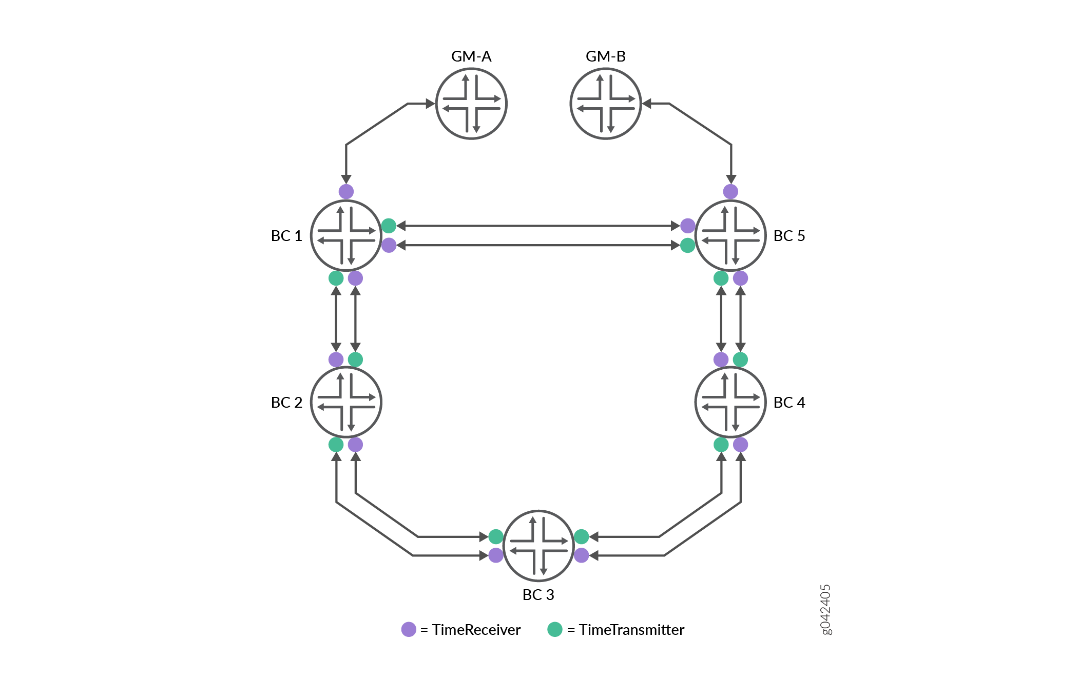
Each boundary clock in the PTP ring is configured as both timeReceiver and timeTransmitter to its immediate neighbor to provide seamless PTP grandmaster clock switchover in case of reference or boundary clock failure. For example, in Figure 1 BC2 is both timeTransmitter and timeReceiver to both BC1 and BC3, BC3 is both timeTransmitter and timeReceiver to BC2 and BC4, and so on.
Path Trace Mechanism for Handling PTP Failures
During the process of synchronization in a PTP ring topology, certain announce messages—timing information messages that are sent from timeTransmitter to timeReceiver—might form in an infinite loop (also called PTP loop) in a network trail of boundary clocks. These PTP loops create issues such as a boundary clock potentially synchronizing its local clock with its own timing information, thereby compromising the quality of the recovered clock. The path trace mechanism is used to detect such loops.
A path trace is the route that a PTP announce message takes through the network trail of boundary clocks and is tracked through the path trace TLV in the announce message. A path trace TLV (type, length, and value) is a set of octets in an announce message that includes the TLV type, the length field, and the path sequence. The path trace sequence contains the clock ID of each boundary clock that an announce message traverses through the PTP ring.
One of the principal uses of the path trace mechanism is to detect the so-called rogue announce messages that circulate endlessly in loops in the PTP ring of boundary clocks. A boundary clock detects a PTP loop when it finds its own clock ID in the path trace of the received announce message. When such a loop is detected, the router discards the received announce message.
To view the trail of the announce message or path trace, use the show ptp
path-trace detail operational mode command.
-
During GRES, the path trace and the best timeTransmitter clock algorithm information are pushed to the kernel. Therefore, this information is available on the backup Routing Engine as well.
-
When the number of boundary clocks in a topology exceeds 20, the path trace TLV is dropped.
-
Currently, the PTP ring topology is supported only for PTP over IPv4 networks.
Steady State
The PTP ring is considered to be in steady state or operating normally when a router, say BC1, is locked—that is, is connected and synchronized—to a grandmaster clock that has a higher quality level value—higher than the quality level of other grandmaster clocks in the network—and all the other routers in the PTP ring are locked to the grandmaster clock through this router BC1. For example in Figure 1, during steady state, BC1 is locked to GM-A, BC2 and BC5 are locked to BC1, BC3 is locked to BC2, and BC4 is locked to BC5. When the path trace mechanism is implemented in this ring topology, a clock ID is assigned to each boundary clock that, in turn, is included in the path trace TLV within the announce message. Therefore, the path trace TLV in the announce message originating from BC1 has its own clock ID—CID1. Similarly, the announce message from BC2 has its own clock ID—CID2—and BC1’s clock ID–CID1—and so on.
As router BC2 is timeTransmitter to BC1, BC1 constantly receives BC2’s announce messages. The announce messages from BC2 received on BC1 contains BC1’s own clock ID—CID1—along with BC2’s clock ID—CID2. Because BC1 receives its own clock ID—CID1—in the announce message, BC1 drops BC2’s announce messages. Similarly, BC2 drops BC3’s announce messages as the messages contain BC2’s clock ID—CID2—along with other clock IDs—CID1 and CID3. Note that this behavior is intentional and by design, as is explained in Failure Handling.
Failure Handling
Consider a scenario where the router BC1 crashes in the PTP ring illustrated in Figure 1. This failure is handled in the following way:
-
The router BC2 stops receiving announce messages from BC1.
-
The announce messages now received by BC2 are only those sent by BC3. BC2 drops these announce messages because these messages contain BC2’s own clock ID—CID2.
-
Because BC2 does not receive any valid announce messages, it goes into holdover mode and lowers the value of its announce parameters, such as clock class, which results in BC2 announce messages carrying an inferior clock class.
-
When BC3 receives these announce messages with inferior clock class from BC2, it in turn announces this inferior clock class to all the downstream routers.
-
When BC5 eventually receives this announce message with the inferior quality level value from BC4, the best timeTransmitter clock algorithm running on the BC5 router switches BC5 to GM-B automatically and the BC5 router sends announce messages corresponding to the parameters as set by GM-B.
-
When BC4 receives this announce message—carrying superior clock class information as compared to that carried by BC3's announce message—the BC4 router switches to BC5. Similarly, BC3 locks to BC4 and then BC2 locks to BC3. In other words, the ring topology shown in Figure 1 converges to a clockwise hierarchy of boundary clocks. This entire process takes a few tens of seconds.
Note that each PTP best timeTransmitter clock algorithm switchover at each boundary clock is seamless and thereby ensures that the performance of the PTP ring does not degrade. However, when there are multiple simultaneous failures in the ring topology—for example, simultaneous link failures between GM-A and BC1 and between BC4 and BC5—the short-term absolute maximum time interval error (MTIE) might go up to 650ns—for example, between routers BC2 to BC4. Note that this type of multiple failures in a ring topology is rare.
MTIE is a maximum phase variation error that is measured over a period of time, where the error is calculated between the phase variation of a signal with the perfect signal.
PTP Ring Topology Without Path Trace Mechanism
When the PTP path trace mechanism is not implemented, the BC2 router cannot detect announce messages from BC3 that are actually BC2’s looped announce messages. This, in turn, results in BC2 attempting to lock to BC3 (while BC3 is already locked to BC2) and a PTP deadlock is created. Because of the PTP deadlock, there is a significant clock drift over a period of time on both BC2 and BC3 and potentially on all the boundary clocks that can be traced to BC3.
Note that when the crashed router BC1 comes up, it chooses GM-A as its timeTransmitter, and it sends out announce messages that carry superior clock class information compared to those carried by announce messages sent out by GM-B. The BC2 router’s best timeTransmitter clock algorithm determines that the BC1’s announce messages carry superior clock class information as compared to BC3’s, resulting in BC2 switching back to BC1. Similarly, BC3 switches back to BC2. This way, the ring topology is restored to the pre-crash topology.