SRv6 Network Programming and Layer 3 Services in BGP Networks
Overview of SRv6 Network Programming and Layer 3 Services over SRv6 in BGP
- Benefits of SRv6 Network Programming
- SRv6 Network Programming in BGP Networks
- Layer 3 VPN Services over the SRv6 Core
- Advertising Layer 3 VPN Services to BGP Peers
- Supported and Unsupported Features for SRv6 Network Programming in BGP
Benefits of SRv6 Network Programming
-
Flexible deployment—BGP leverages the segment routing capability of devices to set up Layer 3 VPN tunnels. SRv6 ingress node can transport IPv4 packets even if the transit routers are not SRv6-capable. This eliminates the need to deploy segment routing on all nodes in an IPv6 network.
-
Seamless deployment—Network programming depends entirely on the IPv6 header and the header extension to transport a packet, eliminating the need for protocols such as MPLS. This ensures a seamless deployment without any major hardware or software upgrade in a core IPv6 network.
-
Single-device versatility—Junos OS supports multiple functions on a single segment identifier (SID) and can inter-operate in the insert mode and the encapsulation mode. This allows a single device to simultaneously play the provider (P) router and the provider edge (PE) router roles.
SRv6 Network Programming in BGP Networks
Network programming is the capability of a network to encode a network program into individual instructions that are inserted into the IPv6 packet headers. The Segment Routing Header (SRH) is a type of IPv6 routing extension header that contains a segment list encoded as an SRv6 SID. An SRv6 SID consists of the locator, which is an IPv6 address, and a function that defines a particular task for each SRv6-capable node in the SRv6 network. SRv6 network programming eliminates the need for MPLS and provides flexibility to leverage segment routing.
Ensure that you use a unique SID, which BGP uses to allocate an SRv6 SID.
To configure IPv4 transport over the SRv6 core, include the
end-dt4-sid
                                                sid
statement at the [edit protocols bgp source-packet-routing
srv6 locator name] hierarchy
level.
To configure IPv6 transport over the SRv6 core, include the
end-dt6-sid sid
statement at the [edit routing protocols bgp
source-packet-routing srv6 locator
name] hierarchy level.
To configure IPv4 and IPv6 transport over the SRv6 core, include the
end-dt46-sid sid
statement at the [edit routing protocols bgp
source-packet-routing srv6 locator
name] hierarchy level. The
end-dt4-sid statement denotes the endpoint SID with de-encapsulation
and IPv4 table lookup. The end dt6-sid statement is the endpoint
with de-encapsulation and IPv6 table lookup. The end-dt46-sid
statement is the endpoint with decapsulation and specific IP table
lookup. The end-dt46 is a variant of end.dt4 and end.dt6 behavior.
BGP allocates these values for IPv4 and IPv6 Layer3 VPN service
SIDs.
Layer 3 VPN Services over the SRv6 Core
When connecting to the egress PE, the ingress PE encapsulates the payload in an outer IPv6 header where the destination address is the SRv6 service SID associated with the related BGP route update. The egress PE sets the next hop to one of its IPv6 addresses that is also the SRv6 locator from which the SRv6 service SID is allocated. Multiple routes can resolve through the same segment routing policy.

You can configure BGP-based Layer 3 service over the SRv6 core. You can enable Layer 3 overlay services with BGP as the control plane and SRv6 as the dataplane. SRv6 network programming provides flexibility to leverage segment routing without deploying MPLS. Such networks depend only on the IPv6 headers and header extensions for transmitting data.
Ensure that the end-dt4-sid
sid and the
end-dt6-sid sid
are the last SIDs in the segment list, or the destination
address of the packet with no SRH header.
To configure IPv4 VPN services over the SRv6 core, include the
end-dt4-sid statement at the [edit
routing-instances instance-name protocols
bgp source-packet-routing srv6 locator
name] hierarchy
level.
The end dt46 SID must be the last segment in a segment routing policy, and a SID instance must be associated with an IPv4 FIB table and an IPv6 FIB table.
Advertising Layer 3 VPN Services to BGP Peers
BGP advertises the reachability of prefixes of a particular service from an egress PE device to ingress PE nodes. BGP messages exchanged between PE devices carry SRv6 service SIDs, which BGP uses to interconnect PE devices to form VPN sessions. For Layer 3 VPN services where BGP uses a per-VRF SID allocation, the same SID is shared across multiple network layer reachability information (NLRI) address families.
To advertise SRv6 services to BGP peers at the egress node, include the
advertise-srv6-service statement at the
[edit protocols bgp family
                                        inet6-vpn
                                        unicast]
hierarchy level.
Egress PE devices that support SRv6-based Layer 3 services advertise overlay service prefixes along with a service SID. The BGP ingress node receives these advertisements and adds the prefix to the corresponding virtual routing and forwarding (VRF) table.
To accept SRv6 services at the ingress node, include the
accept-srv6-service statement at the
[edit protocols bgp family
                                        inet6-vpn
                                        unicast]
hierarchy level.
Supported and Unsupported Features for SRv6 Network Programming in BGP
Junos OS supports the following features with SRv6 Network Programming in BGP:
-
Ingress devices support seven SIDs in the reduced mode including the VPN SID
-
Egress devices support seven SIDs including the VPN SID
-
Endpoint with de-encapsulation and specific IP table lookup (End.DT46 SID)
-
BGP RIB sharding for SRv6 routes. Look up Understanding BGP RIB sharding and BGP Update IO thread and rib-sharding for more information about RIB sharding with SRv6 routes.
-
VPN options C
Junos OS does not support the following features in conjunction with SRv6 Network Programming in BGP:
-
Fragmentation and reassembly in SRv6 tunnels
-
VPN options B
See Also
Example: Configuring Layer 3 Services over SRv6 in BGP Networks
This example shows how to configure SRv6 network programming and Layer 3 VPN services in BGP Networks. SRv6 network programming provides flexibility to leverage segment routing without deploying MPLS. This feature is useful for service providers whose networks are predominantly IPv6 and have not deployed MPLS.
Requirements
This example uses the following hardware and software components:
Five MX Series routers with MPC7E, MPC8E, or MPC9E line cards
Junos OS Release 20.4R1 or later
Overview
You can configure BGP-based Layer 3 services over the SRv6 core network. With SRv6 network programming, networks depend only on the IPv6 headers and header extensions for transmitting data. You can enable Layer 3 overlay services with BGP as the control plane and SRv6 as the dataplane.
Topology
In Figure 2, Router R0 is the ingress and Router R1 and R2 are the egress routers that support IPv4-only customer edge devices. Routers R3 and R4 comprise an IPv6-only provider core network. All routers belong to the same autonomous system. IS-IS is the interior gateway protocol configured to support SRv6 in the IPv6 core routers R3 and R4. In this example, BGP is configured on routers R0, R1, and R2. Router R0 is configured as an IPv6 route reflector with IBGP peering sessions to both Router R1 and Router R2. The egress Router R1 advertises the L3VPN SID to ingress Router R0, which accepts and updates the VRF table.
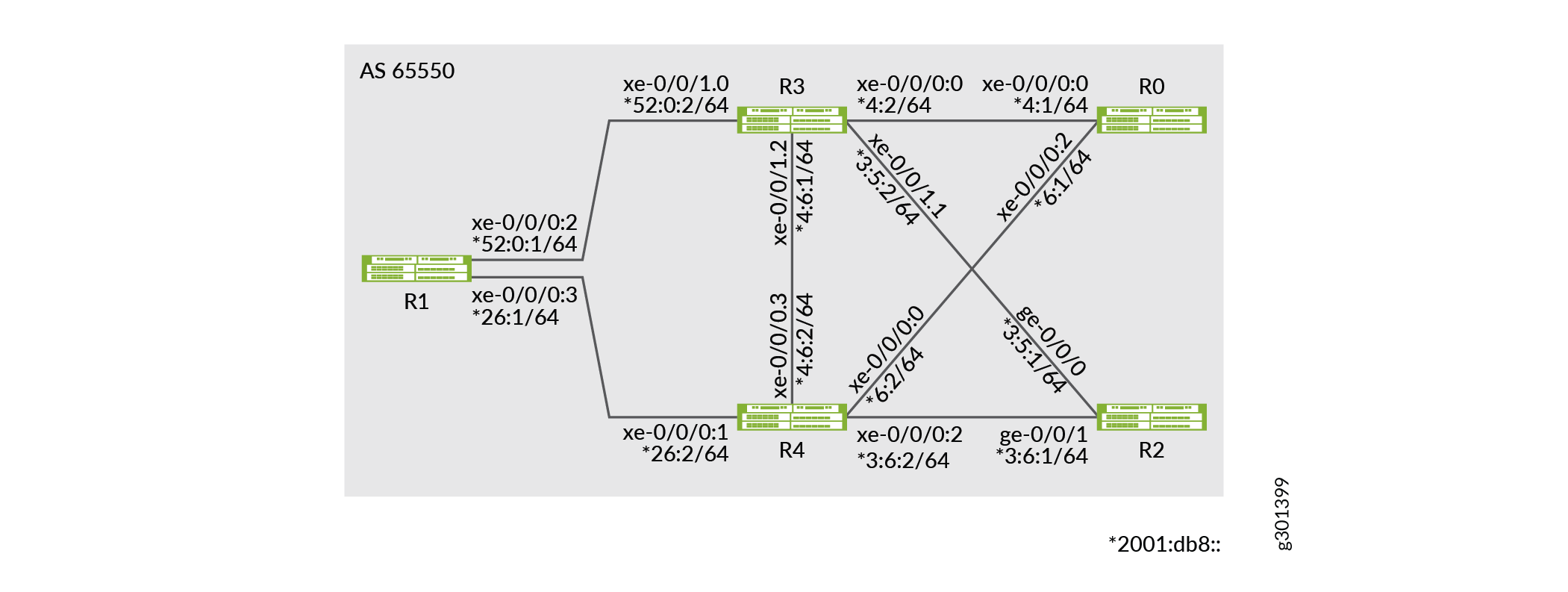
From R1, BGP routes are advertised with next-hop self to Router R0. Router R0 has two paths to R1, the primary path through R3 and the backup path through R4. In Router R0 , the primary path is with default metric and the backup path is configured with metric 50. Here are some of the routes that are advertised from Router R1 to R0:
| IPv4 | 21.0.0.0 |
| IPv6 | 2001:21:: |
| IPv4 VPN | 31.0.0.0 |
| IPv6 VPN | 2001:31:: |
Configuration
CLI Quick Configuration
To quickly configure this example, copy the
following commands, paste them into a text file, remove any line breaks,
change any details necessary to match your network configuration,
copy and paste the commands into the CLI at the [edit] hierarchy
level, and then enter commit from configuration mode.
Router R0
set chassis network-services enhanced-ip
set interfaces xe-0/0/0:0 unit 0 family inet address 1.4.1.1/30
set interfaces xe-0/0/0:0 unit 0 family iso
set interfaces xe-0/0/0:0 unit 0 family inet6 address 2001:db8::4:1/64

set interfaces xe-0/0/0:2 unit 0 family inet address 1.6.1.1/30
set interfaces xe-0/0/0:2 unit 0 family iso
set interfaces xe-0/0/0:2 unit 0 family inet6 address 2001:db8::6:1/64
set interfaces lo0 unit 0 family inet6 address 2001:db8:1:255::0/128
set policy-options policy-statement adv_global term v4 from route-filter 20.0.0.0/8 orlonger
set policy-options policy-statement adv_global term v4 then next-hop self
set policy-options policy-statement adv_global term v4 then accept
set policy-options policy-statement adv_global term v6 from route-filter 2001:20::/64 orlonger
set policy-options policy-statement adv_global term v6 then next-hop self
set policy-options policy-statement adv_global term v6 then accept
set policy-options policy-statement pplb then load-balance per-packet
set policy-options community vpn1-target members target:100:1
set policy-options community vpn2-target members target:100:2
set routing-instances vpn1 protocols bgp group to-TG-vpn1-v4 type external
set routing-instances vpn1 protocols bgp group to-TG-vpn1-v4 local-address 11.1.1.5
set routing-instances vpn1 protocols bgp group to-TG-vpn1-v4 family inet unicast
set routing-instances vpn1 protocols bgp group to-TG-vpn1-v4 family inet6 unicast
set routing-instances vpn1 protocols bgp group to-TG-vpn1-v4 peer-as 1002
set routing-instances vpn1 protocols bgp group to-TG-vpn1-v4 neighbor 11.1.1.6
set routing-instances vpn1 protocols bgp group to-TG-vpn1-v6 type external
set routing-instances vpn1 protocols bgp group to-TG-vpn1-v6 local-address 2001:11:1:1::5
set routing-instances vpn1 protocols bgp group to-TG-vpn1-v6 family inet6 unicast
set routing-instances vpn1 protocols bgp group to-TG-vpn1-v6 peer-as 1002
set routing-instances vpn1 protocols bgp group to-TG-vpn1-v6 neighbor 2001:11:1:1::6
set routing-instances vpn1 protocols bgp source-packet-routing srv6 locator loc1 end-dt4-sid 3001::4
set routing-instances vpn1 protocols bgp source-packet-routing srv6 locator loc1 end-dt6-sid 3001::5
set routing-instances vpn1 instance-type vrf
set routing-instances vpn1 interface xe-0/0/0:3.1
set routing-instances vpn1 route-distinguisher 100:1
set routing-instances vpn1 vrf-target target:100:1
set routing-options source-packet-routing srv6 locator loc1 3001::/64
set routing-options source-packet-routing srv6 no-reduced-srh
set routing-options router-id 128.53.38.52
set routing-options autonomous-system 100
set routing-options forwarding-table export pplb
set protocols bgp group to-PE-all type internal
set protocols bgp group to-PE-all local-address abcd::128:53:38:52
set protocols bgp group to-PE-all family inet unicast extended-nexthop
set protocols bgp group to-PE-all family inet unicast advertise-srv6-service
set protocols bgp group to-PE-all family inet unicast accept-srv6-service
set protocols bgp group to-PE-all family inet-vpn unicast extended-nexthop
set protocols bgp group to-PE-all family inet-vpn unicast advertise-srv6-service
set protocols bgp group to-PE-all family inet-vpn unicast accept-srv6-service
set protocols bgp group to-PE-all family inet6 unicast advertise-srv6-service
set protocols bgp group to-PE-all family inet6 unicast accept-srv6-service
set protocols bgp group to-PE-all family inet6-vpn unicast advertise-srv6-service
set protocols bgp group to-PE-all family inet6-vpn unicast accept-srv6-service
set protocols bgp group to-PE-all export adv_global
set protocols bgp group to-PE-all cluster 128.53.38.52
set protocols bgp group to-PE-all neighbor abcd::128:53:35:39
set protocols bgp group to-PE-all neighbor abcd::128:53:35:35
set protocols bgp group to-TG-global-v4 type external
set protocols bgp group to-TG-global-v4 local-address 11.1.1.1
set protocols bgp group to-TG-global-v4 family inet unicast
set protocols bgp group to-TG-global-v4 family inet6 unicast
set protocols bgp group to-TG-global-v4 peer-as 1001
set protocols bgp group to-TG-global-v4 neighbor 11.1.1.2
set protocols bgp group to-TG-global-v6 type external
set protocols bgp group to-TG-global-v6 local-address 2001:11:1:1::1
set protocols bgp group to-TG-global-v6 family inet6 unicast
set protocols bgp group to-TG-global-v6 peer-as 1001
set protocols bgp group to-TG-global-v6 neighbor 2001:11:1:1::2
set protocols bgp source-packet-routing srv6 locator loc1 end-dt4-sid 3001::2
set protocols bgp source-packet-routing srv6 locator loc1 end-dt6-sid 3001::3
set protocols isis interface all
set protocols isis interface fxp0.0 disable

set protocols isis level 1 disable
Router R1
set chassis network-services enhanced-ip
set interfaces xe-0/0/0:2 unit 0 family inet address 2.5.1.1/30
set interfaces xe-0/0/0:2 unit 0 family iso
set interfaces xe-0/0/0:2 unit 0 family inet6 address 2001:db8::52:0:1/64
set interfaces xe-0/0/0:3 unit 0 family inet address 2.6.1.1/30
set interfaces xe-0/0/0:3 unit 0 family iso
set interfaces xe-0/0/0:3 unit 0 family inet6 address 2001:db8::26:1/64
set policy-options policy-statement adv_global term v4 from route-filter 21.0.0.0/8 orlonger
set policy-options policy-statement adv_global term v4 from route-filter 12.1.1.1/30 orlonger
set policy-options policy-statement adv_global term v4 then next-hop self
set policy-options policy-statement adv_global term v4 then accept
set policy-options policy-statement adv_global term v6 from route-filter 2001:21::/64 orlonger
set policy-options policy-statement adv_global term v6 from route-filter 2001:12:1:1::1/126 orlonger
set policy-options policy-statement adv_global term v6 then next-hop self
set policy-options policy-statement adv_global term v6 then accept
set policy-options policy-statement adv_vpn1 term v4 from route-filter 31.0.0.0/8 orlonger
set policy-options policy-statement adv_vpn1 term v4 from route-filter 12.1.1.5/30 orlonger
set policy-options policy-statement adv_vpn1 term v4 then community set vpn1-target
set policy-options policy-statement adv_vpn1 term v4 then next-hop self
set policy-options policy-statement adv_vpn1 term v4 then accept
set policy-options policy-statement adv_vpn1 term v6 from route-filter 2001:31::/64 orlonger
set policy-options policy-statement adv_vpn1 term v6 from route-filter 2001:12:1:1::5/126 orlonger
set policy-options policy-statement adv_vpn1 term v6 then community set vpn1-target
set policy-options policy-statement adv_vpn1 term v6 then next-hop self
set policy-options policy-statement adv_vpn1 term v6 then accept
set policy-options policy-statement pplb then load-balance per-packet
set policy-options community vpn1-target members target:100:1
set policy-options community vpn2-target members target:100:2
set routing-instances vpn1 protocols bgp group to-TG-vpn1-v4 type external
set routing-instances vpn1 protocols bgp group to-TG-vpn1-v4 local-address 12.1.1.5
set routing-instances vpn1 protocols bgp group to-TG-vpn1-v4 family inet unicast
set routing-instances vpn1 protocols bgp group to-TG-vpn1-v4 family inet6 unicast
set routing-instances vpn1 protocols bgp group to-TG-vpn1-v4 peer-as 1012
set routing-instances vpn1 protocols bgp group to-TG-vpn1-v4 neighbor 12.1.1.6
set routing-instances vpn1 protocols bgp group to-TG-vpn1-v6 type external
set routing-instances vpn1 protocols bgp group to-TG-vpn1-v6 local-address 2001:12:1:1::5
set routing-instances vpn1 protocols bgp group to-TG-vpn1-v6 family inet6 unicast
set routing-instances vpn1 protocols bgp group to-TG-vpn1-v6 peer-as 1012
set routing-instances vpn1 protocols bgp group to-TG-vpn1-v6 neighbor 2001:12:1:1::6
set routing-instances vpn1 protocols bgp source-packet-routing srv6 locator loc1 end-dt4-sid 3011::4
set routing-instances vpn1 protocols bgp source-packet-routing srv6 locator loc1 end-dt6-sid 3011::5
set routing-instances vpn1 instance-type vrf
set routing-instances vpn1 interface xe-0/0/1:0.1
set routing-instances vpn1 route-distinguisher 100:1
set routing-instances vpn1 vrf-export adv_vpn1
set routing-instances vpn1 vrf-target target:100:1
set routing-options source-packet-routing srv6 locator loc1 3011::/64
set routing-options source-packet-routing srv6 no-reduced-srh
set routing-options rib inet6.3 static route abcd::128:53:38:52/128 next-hop self
set routing-options rib inet6.3 static route abcd::128:53:38:52/128 resolve
set routing-options rib inet6.0 static route abcd::128:53:38:52/128 next-hop self
set routing-options rib inet6.0 static route abcd::128:53:38:52/128 resolve
set routing-options autonomous-system 100
set routing-options forwarding-table export pplb
set protocols bgp group to-RR type internal
set protocols bgp group to-RR local-address abcd::128:53:35:39
set protocols bgp group to-RR family inet unicast extended-nexthop
set protocols bgp group to-RR family inet unicast advertise-srv6-service
set protocols bgp group to-RR family inet unicast accept-srv6-service
set protocols bgp group to-RR family inet-vpn unicast extended-nexthop
set protocols bgp group to-RR family inet-vpn unicast advertise-srv6-service
set protocols bgp group to-RR family inet-vpn unicast accept-srv6-service
set protocols bgp group to-RR family inet6 unicast advertise-srv6-service
set protocols bgp group to-RR family inet6 unicast accept-srv6-service
set protocols bgp group to-RR family inet6-vpn unicast advertise-srv6-service
set protocols bgp group to-RR family inet6-vpn unicast accept-srv6-service
set protocols bgp group to-RR export adv_global
set protocols bgp group to-RR neighbor abcd::128:53:38:52
set protocols bgp group to-TG-global-v4 type external
set protocols bgp group to-TG-global-v4 local-address 12.1.1.1
set protocols bgp group to-TG-global-v4 family inet unicast
set protocols bgp group to-TG-global-v4 family inet6 unicast
set protocols bgp group to-TG-global-v4 peer-as 1011
set protocols bgp group to-TG-global-v4 neighbor 12.1.1.2
set protocols bgp group to-TG-global-v6 type external
set protocols bgp group to-TG-global-v6 local-address 2001:12:1:1::1
set protocols bgp group to-TG-global-v6 family inet6 unicast
set protocols bgp group to-TG-global-v6 peer-as 1011
set protocols bgp group to-TG-global-v6 neighbor 2001:12:1:1::2
set protocols bgp source-packet-routing srv6 locator loc1 end-dt4-sid 3011::2
set protocols bgp source-packet-routing srv6 locator loc1 end-dt6-sid 3011::3
set protocols isis interface all
set protocols isis interface fxp0.0 disable

set protocols isis level 1 disable
Router R2
set chassis network-services enhanced-ip
set interfaces ge-0/0/0 unit 0 family inet address 3.5.1.1/30
set interfaces ge-0/0/0 unit 0 family iso
set interfaces ge-0/0/0 unit 0 family inet6 address 2001:db8::3:5:1/64
set interfaces ge-0/0/1 unit 0 family inet address 3.6.1.1/30
set interfaces ge-0/0/1 unit 0 family iso
set interfaces ge-0/0/1 unit 0 family inet6 address 2001:db8::3:6:1/64
set interfaces lo0 unit 0 family inet6 address 2001:db8:1:255::2/128
set policy-options policy-statement adv_global term v4 from route-filter 22.0.0.0/8 orlonger
set policy-options policy-statement adv_global term v4 from route-filter 13.1.1.1/30 orlonger
set policy-options policy-statement adv_global term v4 then next-hop self
set policy-options policy-statement adv_global term v4 then accept
set policy-options policy-statement adv_global term v6 from route-filter 2001:22::/64 orlonger
set policy-options policy-statement adv_global term v6 from route-filter 2001:13:1:1::1/126 orlonger
set policy-options policy-statement adv_global term v6 then next-hop self
set policy-options policy-statement adv_global term v6 then accept
set policy-options policy-statement adv_vpn1 term v4 from route-filter 32.0.0.0/8 orlonger
set policy-options policy-statement adv_vpn1 term v4 from route-filter 13.1.1.5/30 orlonger
set policy-options policy-statement adv_vpn1 term v4 then community set vpn1-target
set policy-options policy-statement adv_vpn1 term v4 then next-hop self
set policy-options policy-statement adv_vpn1 term v4 then accept
set policy-options policy-statement adv_vpn1 term v6 from route-filter 2001:32::/64 orlonger
set policy-options policy-statement adv_vpn1 term v6 from route-filter 2001:13:1:1::5/126 orlonger
set policy-options policy-statement adv_vpn1 term v6 then community set vpn1-target
set policy-options policy-statement adv_vpn1 term v6 then next-hop self
set policy-options policy-statement adv_vpn1 term v6 then accept
set policy-options policy-statement pplb then load-balance per-packet
set policy-options community vpn1-target members target:100:1
set routing-instances vpn1 protocols bgp group to-TG-vpn1-v4 type external
set routing-instances vpn1 protocols bgp group to-TG-vpn1-v4 local-address 13.1.1.5
set routing-instances vpn1 protocols bgp group to-TG-vpn1-v4 family inet unicast
set routing-instances vpn1 protocols bgp group to-TG-vpn1-v4 family inet6 unicast
set routing-instances vpn1 protocols bgp group to-TG-vpn1-v4 peer-as 1022
set routing-instances vpn1 protocols bgp group to-TG-vpn1-v4 neighbor 13.1.1.6
set routing-instances vpn1 protocols bgp group to-TG-vpn1-v6 type external
set routing-instances vpn1 protocols bgp group to-TG-vpn1-v6 local-address 2001:13:1:1::5
set routing-instances vpn1 protocols bgp group to-TG-vpn1-v6 family inet6 unicast
set routing-instances vpn1 protocols bgp group to-TG-vpn1-v6 peer-as 1022
set routing-instances vpn1 protocols bgp group to-TG-vpn1-v6 neighbor 2001:13:1:1::6
set routing-instances vpn1 protocols bgp source-packet-routing srv6 locator loc1 end-dt4-sid 3021::4
set routing-instances vpn1 protocols bgp source-packet-routing srv6 locator loc1 end-dt6-sid 3021::5
set routing-instances vpn1 instance-type vrf
set routing-instances vpn1 interface ge-0/0/2.1
set routing-instances vpn1 route-distinguisher 100:1
set routing-instances vpn1 vrf-export adv_vpn1
set routing-instances vpn1 vrf-target target:100:1
set routing-options source-packet-routing srv6 locator loc1 3021::/64
set routing-options source-packet-routing srv6 no-reduced-srh
set routing-options rib inet6.3 static route abcd::128:53:38:52/128 next-hop self
set routing-options rib inet6.3 static route abcd::128:53:38:52/128 resolve
set routing-options rib inet6.0 static route abcd::128:53:38:52/128 next-hop self
set routing-options rib inet6.0 static route abcd::128:53:38:52/128 resolve
set routing-options autonomous-system 100
set routing-options forwarding-table export pplb
set protocols bgp group to-RR type internal
set protocols bgp group to-RR local-address abcd::128:53:35:35
set protocols bgp group to-RR family inet unicast extended-nexthop
set protocols bgp group to-RR family inet unicast advertise-srv6-service
set protocols bgp group to-RR family inet unicast accept-srv6-service
set protocols bgp group to-RR family inet-vpn unicast extended-nexthop
set protocols bgp group to-RR family inet-vpn unicast advertise-srv6-service
set protocols bgp group to-RR family inet-vpn unicast accept-srv6-service
set protocols bgp group to-RR family inet6 unicast advertise-srv6-service
set protocols bgp group to-RR family inet6 unicast accept-srv6-service
set protocols bgp group to-RR family inet6-vpn unicast advertise-srv6-service
set protocols bgp group to-RR family inet6-vpn unicast accept-srv6-service
set protocols bgp group to-RR export adv_global
set protocols bgp group to-RR neighbor abcd::128:53:38:52
set protocols bgp group to-TG-global-v4 type external
set protocols bgp group to-TG-global-v4 local-address 13.1.1.1
set protocols bgp group to-TG-global-v4 family inet unicast
set protocols bgp group to-TG-global-v4 family inet6 unicast
set protocols bgp group to-TG-global-v4 peer-as 1021
set protocols bgp group to-TG-global-v4 neighbor 13.1.1.2
set protocols bgp group to-TG-global-v6 type external
set protocols bgp group to-TG-global-v6 local-address 2001:13:1:1::1
set protocols bgp group to-TG-global-v6 family inet6 unicast
set protocols bgp group to-TG-global-v6 peer-as 1021
set protocols bgp group to-TG-global-v6 neighbor 2001:13:1:1::2
set protocols bgp source-packet-routing srv6 locator loc1 end-dt4-sid 3021::2
set protocols bgp source-packet-routing srv6 locator loc1 end-dt6-sid 3021::3
set protocols isis interface all
set protocols isis interface fxp0.0 disable

set protocols isis level 1 disable
Router R3
set chassis network-services enhanced-ip
set interfaces xe-0/0/0:0 unit 0 family inet address 1.4.1.2/30
set interfaces xe-0/0/0:0 unit 0 family iso
set interfaces xe-0/0/0:0 unit 0 family inet6 address 2001:db8::4:2/64
set interfaces xe-0/0/1:0 unit 0 family inet address 2.5.1.2/30
set interfaces xe-0/0/1:0 unit 0 family iso
set interfaces xe-0/0/1:0 unit 0 family inet6 address 2001:db8::52:0:2/64
set interfaces xe-0/0/1:1 unit 0 family inet address 3.5.1.2/30
set interfaces xe-0/0/1:1 unit 0 family iso
set interfaces xe-0/0/1:1 unit 0 family inet6 address 2001:db8::3:5:2/64
set interfaces xe-0/0/1:2 unit 0 family inet address 4.6.1.1/30
set interfaces xe-0/0/1:2 unit 0 family iso
set interfaces xe-0/0/1:2 unit 0 family inet6 address 2001:db8::4:6:1/64
set interfaces lo0 unit 0 family inet6 address 2001:db8:1:255::3/128
set routing-options autonomous-system 100
set protocols isis interface all
set protocols isis interface fxp0.0 disable
set protocols isis level 1 disable
Router R4
set chassis network-services enhanced-ip
set interfaces xe-0/0/0:0 unit 0 family inet address 1.6.1.2/30
set interfaces xe-0/0/0:0 unit 0 family iso
set interfaces xe-0/0/0:0 unit 0 family inet6 address 2001:db8::6:2/64
set interfaces xe-0/0/0:1 unit 0 family inet address 2.6.1.2/30
set interfaces xe-0/0/0:1 unit 0 family iso
set interfaces xe-0/0/0:1 unit 0 family inet6 address 2001:db8::26:2/64
set interfaces xe-0/0/0:2 unit 0 family inet address 3.6.1.2/30
set interfaces xe-0/0/0:2 unit 0 family iso
set interfaces xe-0/0/0:2 unit 0 family inet6 address 2001:db8::3:6:2/64
set interfaces xe-0/0/0:3 unit 0 family inet address 4.6.1.2/30
set interfaces xe-0/0/0:3 unit 0 family iso
set interfaces xe-0/0/0:3 unit 0 family inet6 address 2001:db8::4:6:2/64
set interfaces lo0 unit 0 family inet6 address 2001:db8:1:255::4/128
set routing-options autonomous-system 100
set protocols isis interface all
set protocols isis interface fxp0.0 disable
set protocols isis level 1 disable
Configure Router R0
Step-by-Step Procedure
To configure SRv6 network programming with Layer 3 VPN services, perform the following steps on Router R0:
Configure the device interfaces to enable IP transport.
[edit]
user@R0# set interfaces xe-0/0/0:0 unit 0 family inet address 1.4.1.1/30
user@R0# set interfaces xe-0/0/0:0 unit 0 family iso
user@R0# set interfaces xe-0/0/0:0 unit 0 family inet6 address 2001:db8::4:1/64

user@R0# set interfaces xe-0/0/0:2 unit 0 family inet address 1.6.1.1/30
user@R0# set interfaces xe-0/0/0:2 unit 0 family iso
user@R0# set interfaces xe-0/0/0:2 unit 0 family inet6 address 2001:db8::6:1/64
Configure the router ID and autonomous system (AS) number to propagate routing information within a set of routing devices that belong to the same AS.
[edit]
user@R0# set routing-options router-id 128.53.38.52
user@R0# set routing-options autonomous-system 100
Enable SRv6 globally and the locator address to indicate the SRv6 capability of the router. SRv6 SID is an IPv6 address that consists of the locator and a function. The routing protocols advertise the locator addresses.
[edit]
user@R0# set routing-options source-packet-routing srv6 locator loc1 3001::/64
user@R0# set routing-options source-packet-routing srv6 no-reduced-srh
Configure an external routing instance VPN1 for both IPv4 and IPv6 traffic. Configure the BGP protocol for VPN1 to enable peering and traffic transport between the provider edge devices.
[edit]
user@R0# set routing-instances vpn1 protocols bgp group to-TG-vpn1-v4 type external
user@R0# set routing-instances vpn1 protocols bgp group to-TG-vpn1-v4 local-address 11.1.1.5
user@R0# set routing-instances vpn1 protocols bgp group to-TG-vpn1-v4 family inet unicast
user@R0# set routing-instances vpn1 protocols bgp group to-TG-vpn1-v4 family inet6 unicast
user@R0# set routing-instances vpn1 protocols bgp group to-TG-vpn1-v4 peer-as 1002
user@R0# set routing-instances vpn1 protocols bgp group to-TG-vpn1-v4 neighbor 11.1.1.6
user@R0# set routing-instances vpn1 protocols bgp group to-TG-vpn1-v6 type external
user@R0# set routing-instances vpn1 protocols bgp group to-TG-vpn1-v6 local-address 2001:11:1:1::5
user@R0# set routing-instances vpn1 protocols bgp group to-TG-vpn1-v6 family inet6 unicast
user@R0# set routing-instances vpn1 protocols bgp group to-TG-vpn1-v6 peer-as 1002
user@R0# set routing-instances vpn1 protocols bgp group to-TG-vpn1-v6 neighbor 2001:11:1:1::6
Configure the VPN type and a unique route distinguisher for each PE router participating in the routing instance.
[edit]
user@R0# set routing-instances vpn1 instance-type vrf
user@R0# set routing-instances vpn1 interface xe-0/0/0:3.1
user@R0# set routing-instances vpn1 route-distinguisher 100:1
user@R0# set routing-instances vpn1 vrf-target target:100:1
Configure the end-dt4 and end-dt6 SID values for enabling the Layer 3 VPN services.
[edit]
user@R0# set routing-instances vpn1 protocols bgp source-packet-routing srv6 locator loc1 end-dt4-sid 3001::4
user@R0# set routing-instances vpn1 protocols bgp source-packet-routing srv6 locator loc1 end-dt6-sid 3001::5
Define a policy to load-balance packets.
[edit]
user@R0# set policy-options policy-statement pplb then load-balance per-packet
user@R0# set policy-options community vpn1-target members target:100:1
user@R0# set policy-options community vpn2-target members target:100:2
Apply the per-packet policy to enable load balancing of traffic.
[edit]
user@R0# set routing-options forwarding-table export pplb
Define a policy adv_global to accept routes advertised from R1.
[edit]
user@R0# set policy-options policy-statement adv_global term v4 from route-filter 20.0.0.0/8 orlonger
user@R0# set policy-options policy-statement adv_global term v4 then next-hop self
user@R0# set policy-options policy-statement adv_global term v4 then accept
user@R0# set policy-options policy-statement adv_global term v6 from route-filter 2001:20::/64 orlonger
user@R0# set policy-options policy-statement adv_global term v6 then next-hop self
user@R0# set policy-options policy-statement adv_global term v6 then accept
Configure BGP on the core-facing interface to establish internal and external peering sessions.
[edit]
user@R0# set protocols bgp group to-PE-all type internal
user@R0# set protocols bgp group to-PE-all local-address abcd::128:53:38:52
user@R0# set protocols bgp group to-PE-all family inet unicast extended-nexthop
user@R0# set protocols bgp group to-PE-all family inet unicast advertise-srv6-service
user@R0# set protocols bgp group to-PE-all family inet unicast accept-srv6-service
user@R0# set protocols bgp group to-PE-all family inet-vpn unicast extended-nexthop
user@R0# set protocols bgp group to-PE-all export adv_global
user@R0# set protocols bgp group to-PE-all cluster 128.53.38.52
user@R0# set protocols bgp group to-PE-all neighbor abcd::128:53:35:39
user@R0# set protocols bgp group to-PE-all neighbor abcd::128:53:35:35
user@R0# set protocols bgp group to-TG-global-v4 type external
user@R0# set protocols bgp group to-TG-global-v4 local-address 11.1.1.1
user@R0# set protocols bgp group to-TG-global-v4 family inet unicast
user@R0# set protocols bgp group to-TG-global-v4 family inet6 unicast
user@R0# set protocols bgp group to-TG-global-v4
user@R0# set protocols bgp group to-TG-global-v4 neighbor 11.1.1.2
user@R0# set protocols bgp group to-TG-global-v6 type external
user@R0# set protocols bgp group to-TG-global-v6 local-address 2001:11:1:1::1
user@R0# set protocols bgp group to-TG-global-v6 family inet6 unicast
user@R0# set protocols bgp group to-TG-global-v6 peer-as 1001
user@R0# set protocols bgp group to-TG-global-v6 neighbor 2001:11:1:1::2
Enable the device to advertise the SRv6 services to BGP peers and to accept the routes advertised by the egress provider edge (PE) devices.
[edit]
user@R0# set protocols bgp group to-PE-all family inet-vpn unicast advertise-srv6-service
user@R0# set protocols bgp group to-PE-all family inet-vpn unicast accept-srv6-service
user@R0# set protocols bgp group to-PE-all family inet6 unicast advertise-srv6-service
user@R0# set protocols bgp group to-PE-all family inet6 unicast accept-srv6-service
user@R0# set protocols bgp group to-PE-all family inet6-vpn unicast advertise-srv6-service
user@R0# set protocols bgp group to-PE-all family inet6-vpn unicast accept-srv6-service
Enable IS-IS as the interior gateway protocol (IGP) for routing traffic between the core provider routers.
[edit]
user@R0# set protocols isis interface all
user@R0# set protocols isis interface fxp0.0 disable
user@R0#
user@R0# set protocols isis level 1 disable
Configure the end-dt4 and end-dt6 SID value for the prefix segments. End-dt4 is the endpoint SID with decapsulation and IPv4 table lookup and end-dt6 is the endpoint with decapsulation and IPv6 table lookup. BGP allocates these for IPv4 and IPv6 Layer3 VPN services SIDs.
[edit]
user@R0# set protocols bgp source-packet-routing srv6 locator loc1 end-dt4-sid 3001::2
user@R0# set protocols bgp source-packet-routing srv6 locator loc1 end-dt6-sid 3001::3
Results
From configuration mode, confirm your configuration
by entering the show interfaces, show protocols, show policy-options, and show routing-options commands. If the output does not display the intended configuration,
repeat the instructions in this example to correct the configuration.
[edit]
user@R0# show interfaces
xe-0/0/0:0 {
    unit 0 {
        family inet {
            address 1.4.1.1/30;
        }
        family iso;
        family inet6 {
            address 2001:db8::4:1/64;
        }
    }
}
xe-0/0/0:1 {
    unit 0 {
        family inet {
            address 1.5.1.1/30;
        }
        family iso;
        family inet6 {
            address 2001:1:4:2::1/126;
        }
    }
}
xe-0/0/0:2 {
    unit 0 {
        family inet {
            address 1.6.1.1/30;
        }
        family iso;
        family inet6 {
            address 2001:db8::6:1/64;
        }
    }
}
[edit]
user@R0# show protocols
bgp {
    group to-PE-all {
        type internal;
        local-address abcd::128:53:38:52;
        family inet {
            unicast {
                extended-nexthop;
                advertise-srv6-service;
                accept-srv6-service;
            }
        }
        family inet-vpn {
            unicast {
                extended-nexthop;
                advertise-srv6-service;
                accept-srv6-service;
            }
        }
        family inet6 {
            unicast {
                advertise-srv6-service;
                accept-srv6-service;
            }
        }
        family inet6-vpn {
            unicast {
                advertise-srv6-service;
                accept-srv6-service;
            }
        }
        export adv_global;
        cluster 128.53.38.52;
        neighbor abcd::128:53:35:39;
        neighbor abcd::128:53:35:35;
    }
    group to-TG-global-v4 {
        type external;
        local-address 11.1.1.1;
        family inet {
            unicast;
        }
        family inet6 {
            unicast;
        }
        peer-as 1001;
        neighbor 11.1.1.2;
    }
    group to-TG-global-v6 {
        type external;
        local-address 2001:11:1:1::1;
        family inet6 {
            unicast;
        }
        peer-as 1001;
        neighbor 2001:11:1:1::2;
    }
    source-packet-routing {
        srv6 {
            locator loc1 {
                end-dt4-sid 3001::2;
                end-dt6-sid 3001::3;
            }
        }
    }
}
isis {
    interface all;
    interface fxp0.0 {
        disable;
    }

    level 1 disable;
}
[edit]
user@R0# show policy-options
policy-options {
    policy-statement adv_global {
        term v4 {
            from {
                route-filter 20.0.0.0/8 orlonger;
            }
            then {
                next-hop self;
                accept;
            }
        }
        term v6 {
            from {
                route-filter 2001:20::/64 orlonger;
            }
            then {
                next-hop self;
                accept;
            }
        }
    }
    policy-statement pplb {
        then {
            load-balance per-packet;
        }
    }
    community vpn1-target members target:100:1;
    community vpn2-target members target:100:2;
}
[edit]
user@R0# show routing-options
routing-options {
    source-packet-routing {
        srv6 {
            locator loc1 3001::/64;
            no-reduced-srh;
        }
    }

    router-id 128.53.38.52;
    autonomous-system 100;
    forwarding-table {
        export pplb;
    }
}
[edit]
user@R0# show routing-instances
routing-instances {
    vpn1 {
        protocols {
            bgp {
                group to-TG-vpn1-v4 {
                    type external;
                    local-address 11.1.1.5;
                    family inet {
                        unicast;
                    }
                    family inet6 {
                        unicast;
                    }
                    peer-as 1002;
                    neighbor 11.1.1.6;
                }
                group to-TG-vpn1-v6 {
                    type external;
                    local-address 2001:11:1:1::5;
                    family inet6 {
                        unicast;
                    }
                    peer-as 1002;
                    neighbor 2001:11:1:1::6;
                }
                source-packet-routing {
                    srv6 {
                        locator loc1 {
                            end-dt4-sid 3001::4;
                            end-dt6-sid 3001::5;
                        }
                    }
                }
            }
        }
        instance-type vrf;
        interface xe-0/0/0:3.1;
        route-distinguisher 100:1;
        vrf-target target:100:1;
    }
}
When done configuring the device, enter commit from
the configuration mode.
Verification
Confirm that the configuration is working properly.
- Verify that the advertised IPv4 route is installed in the IPv4 table
- Verify that SRv6 SID is installed in the IPv4 Table
- Verify that the IPv6 VPN route is installed in the VPN table
- Verify that the IPv4 VPN route is installed in the VPN table
Verify that the advertised IPv4 route is installed in the IPv4 table
Purpose
Verify that ingress router R0 has learned the route to the IPv4 prefix 21.0.0.0 from the egress router R1.
Action
From operational mode, run the show route 21.0.0.0 command on router R0.
user@R0> show route 21.0.0.0
inet.0: 59 destinations, 59 routes (59 active, 0 holddown, 0 hidden)
+ = Active Route, - = Last Active, * = Both

21.0.0.0/30        *[BGP/170] 09:15:25, localpref 100, from abcd::128:53:37:72
                      AS path: {65501} I, validation-state: unverified
                    >  to fe80::2e6b:f5ff:fe28:2bcb via ae0.0, SRV6-Tunnel, Dest: 3011::
                       to fe80::2e6b:f5ff:fe28:2b04 via xe-0/0/0:2.0, SRV6-Tunnel, Dest: 3011::
                       to fe80::2e6b:f5ff:fe73:1e01 via xe-0/0/0:3.0, SRV6-Tunnel, Dest: 3011::
Meaning
The output confirms that the IPv4 prefix 21.0.0.0 is installed in the inet.0 table.
Verify that SRv6 SID is installed in the IPv4 Table
Purpose
Verify that ingress Router R0 has received and accepted the SRv6 end-dt4 SID 3011::2 from the egress Router R1.
Action
From operational mode, run the show route 21.0.0.0 extensive command on Router R0.
user@> show route 21.0.0.0 extensive
inet.0: 59 destinations, 59 routes (59 active, 0 holddown, 0 hidden)
21.0.0.0/30 (1 entry, 1 announced)
TSI:
KRT in-kernel 21.0.0.0/30 -> {composite(716)}
        *BGP    Preference: 170/-101
                Next hop type: Indirect, Next hop index: 0
                Address: 0xc5aa39c
                Next-hop reference count: 20
                Source: abcd::128:53:37:72
                Next hop type: List, Next hop index: 1048574
        Next hop: ELNH Address 0xc5a9e88, selected
            Next hop type: Chain, Next hop index: 725
            Address: 0xc5a9e88
            Next-hop reference count: 1
            Next hop: ELNH Address 0xc5a9aa0
            SRV6-Tunnel: Reduced-SRH Encap-mode
             Src: abcd::128:53:35:39 Dest: 3011::
             Segment-list[0] 3011::
                Next hop type: Router, Next hop index: 700
                Address: 0xc5a9aa0
                Next-hop reference count: 4
                Next hop: fe80::2e6b:f5ff:fe28:2bcb via ae0.0
        Next hop: ELNH Address 0xc5a9eec
            Next hop type: Chain, Next hop index: 726
            Address: 0xc5a9eec
            Next-hop reference count: 1
            Next hop: ELNH Address 0xc5a9c30
            SRV6-Tunnel: Reduced-SRH Encap-mode
             Src: abcd::128:53:35:39 Dest: 3011::
             Segment-list[0] 3011::
                Next hop type: Router, Next hop index: 702
                Address: 0xc5a9c30
                Next-hop reference count: 4
                Next hop: fe80::2e6b:f5ff:fe28:2b04 via xe-0/0/0:2.0
        Next hop: ELNH Address 0xc5aa0e0
            Next hop type: Chain, Next hop index: 727
            Address: 0xc5aa0e0
            Next-hop reference count: 1
            Next hop: ELNH Address 0xc5a9780
            SRV6-Tunnel: Reduced-SRH Encap-mode
             Src: abcd::128:53:35:39 Dest: 3011::
             Segment-list[0] 3011::
                Next hop type: Router, Next hop index: 647
                Address: 0xc5a9780
                Next-hop reference count: 20
                Next hop: fe80::2e6b:f5ff:fe73:1e01 via xe-0/0/0:3.0
                Protocol next hop: abcd::128:53:37:72
                Composite next hop: 0xbd4e7d0 716 INH Session ID: 0x151
                Indirect next hop: 0xc762204 1048582 INH Session ID: 0x151
                State: <Active int Ext>
                Local AS:   100 Peer AS:   100
                Age: 9:13:44    Metric2: 20
                Validation State: unverified
                ORR Generation-ID: 0
                Task: BGP_100.abcd::128:53:37:72
                Announcement bits (1): 0-KRT
                AS path: {65501}
                Accepted
                SRv6 SID: 3011::2
                Localpref: 100
                Router ID: 128.53.37.72
                Composite next hops: 1
                         Protocol next hop: abcd::128:53:37:72 Metric: 20
                         Composite next hop: 0xbd4e7d0 716 INH Session ID: 0x151
                         Indirect next hop: 0xc762204 1048582 INH Session ID: 0x151
                         Indirect path forwarding next hops: 3
                                 Next hop type: List
                                 Next hop: fe80::2e6b:f5ff:fe28:2bcb via ae0.0
                                 Next hop: fe80::2e6b:f5ff:fe28:2b04 via xe-0/0/0:2.0
                                 Next hop: fe80::2e6b:f5ff:fe73:1e01 via xe-0/0/0:3.0
                                 abcd::128:53:37:72/128 Originating RIB: inet6.3
                                   Metric: 20 Node path count: 1
                                   Indirect next hops: 1
                                 Protocol next hop: 3011:: Metric: 20
                                 Inode flags: 0x206 path flags: 0x0
                                 Path fnh link: 0xc3bf4c0 path inh link: 0x0
                                 Indirect next hop: 0xc76cd04 - INH Session ID: 0x0
                                 Indirect path forwarding next hops: 3
                                         Next hop type: List
                                         Next hop: fe80::2e6b:f5ff:fe28:2bcb via ae0.0
                                         Next hop: fe80::2e6b:f5ff:fe28:2b04 via xe-0/0/0:2.0
                                         Next hop: fe80::2e6b:f5ff:fe73:1e01 via xe-0/0/0:3.0
                                         3011:: Originating RIB: inet6.3
                                           Metric: 20 Node path count: 1
                                           Forwarding nexthops: 3
                                                 Next hop type: List
                                                 Next hop: fe80::2e6b:f5ff:fe28:2bcb via ae0.0
                                                 Next hop: fe80::2e6b:f5ff:fe28:2b04 via xe-0/0/0:2.0
                                                 Next hop: fe80::2e6b:f5ff:fe73:1e01 via xe-0/0/0:3.0
Meaning
The output displays the SRv6 SID and confirms that an SRv6 tunnel is established between Routers R0 and R1.
Verify that the IPv6 VPN route is installed in the VPN table
Purpose
Verify that ingress router R0 has learned the route to the VPN IPv6 prefix 2001::30::/126 from the egress router R1.
Action
From operational mode, run the show route 2001:31:: command on router R0.
user@R0> show route 2001:31::
vpn1.inet6.0: 36 destinations, 36 routes (36 active, 0 holddown, 0 hidden)
+ = Active Route, - = Last Active, * = Both

2001:31::/126      *[BGP/170] 09:15:40, localpref 100, from abcd::128:53:37:72
                      AS path: {65502} I, validation-state: unverified
                    >  to fe80::2e6b:f5ff:fe28:2bcb via ae0.0, SRV6-Tunnel, Dest: 3011::
                       to fe80::2e6b:f5ff:fe28:2b04 via xe-0/0/0:2.0, SRV6-Tunnel, Dest: 3011::
                       to fe80::2e6b:f5ff:fe73:1e01 via xe-0/0/0:3.0, SRV6-Tunnel, Dest: 3011::
Meaning
The output confirms that the route details for the prefix 2001:31::/126 are installed in the vpn.inet6.0 table.
Verify that the IPv4 VPN route is installed in the VPN table
Purpose
Verify that ingress router R0 has learned the route to the VPN IPv4 prefix 31.0.0.0 from the egress router R1.
Action
From operational mode, run the show route 31.0.0.0 command on router R0.
user@R0> show route 31.0.0.0
vpn1.inet.0: 34 destinations, 34 routes (34 active, 0 holddown, 0 hidden)
+ = Active Route, - = Last Active, * = Both

31.0.0.0/30        *[BGP/170] 09:15:29, localpref 100, from abcd::128:53:37:72
                      AS path: {65502} I, validation-state: unverified
                       to fe80::2e6b:f5ff:fe28:2bcb via ae0.0, SRV6-Tunnel, Dest: 3011::
                       to fe80::2e6b:f5ff:fe28:2b04 via xe-0/0/0:2.0, SRV6-Tunnel, Dest: 3011::
                    >  to fe80::2e6b:f5ff:fe73:1e01 via xe-0/0/0:3.0, SRV6-Tunnel, Dest: 3011::
Meaning
The output confirms that the IPv4 prefix 31.0.0.0 is installed in the vpn.inet.0 table.
Change History Table
Feature support is determined by the platform and release you are using. Use Feature Explorer to determine if a feature is supported on your platform.