
TTL propagation for SRv6 Tunnels
TTL propagation for SRv6 tunnels to allow traceroute probe packets generated by customer edge (CE) node to have time to live (TTL) or hop limit (HL) expiry on SRv6 nodes. Enable SRv6 hop-by-hop traceroute visibility by tunneling ICMP error messages through the SRv6 path.
Time-to-Live (TTL) propagation in Segment Routing with IPv6 (SRv6) prevents routing loops and provides accurate traceroute visibility across transit tunnels. It ensures that the TTL or hop limit (HL) in the inner payload is tied to the outer SRv6 tunnel header. The TTL or HL is propagated between the inner payload (IPv4, IPv6, or MPLS header) and the outer SRv6 IPv6 header during encapsulation and decapsulation on the ingress and egress nodes of an SRv6 tunnel. This enables traceroute packets generated by a customer edge (CE) node to have TTL or HL expire on the SRv6 nodes, including the transit nodes. During decapsulation, TTL propagation takes place only if the outer header TTL is less than the inner header TTL, to keep the behavior consistent with loop prevention mechanisms.
TTL propagation is enabled by default. You can disable this behavior by
configuring no-propagate-ttl statement at the [edit routing-options
source-packet-routing srv6] hierarchy
level.
In SRv6 networks, traceroute from CE to CE devices did not list any transit provider routers. Network operators had no visibility into the SRv6 underlay path making it extremely difficult to isolate where packet loss, latency, or forwarding issues occurred within the SRv6 domain. This feature enables tunneling of ICMP error messages through the SRv6 path so that the egress node can deliver them to the original source with the correct VPN or VRF context.
You can enable tunneling of ICMP error messages in the core for hop-by-hop SRv6 traceroute
visibility for SRv6 tunnels. Include the icmp-tunneling statement at the
[edit routing-options
        source-packet-routing srv6]
hierarchy level on
transit nodes to generate and encapsulate ICMP error message.
Figure 1, illustrates a network packet flow through an SRv6 tunnel (PE1 to PE2), showing detailed header information at each stage. PE1 is the ingress device that propagates the HL from the payload (IPv6 header) to the SRv6 header. The HL decrements at every hop and expires at P2. With ICMP tunneling enabled, P2 generates an ICMP error message and encapsulates it as follows:
| Packet Type | Description |
|---|---|
| Inner Payload IPv6 header and packet | Original traceroute probe |
| ICMPv6 packet | Source address: IPv6 address of the local node Destination address: IPv6 source address of the original traceroute probe Hop Limit: 255 |
| IPv6 header | Source address: IPv6 address of the original IPv6 outer header Destination address: IPv6 address of the original IPv6 outer header Hop Limit: 255 |
If the original packet has multiple transport outer IPv6 headers or Segment Routing Header (SRH) all but the most outer IPv6 header are copied into the encapsulated packet on top of the ICMPv6 header. The outer IPv6 header is constructed as explained above.
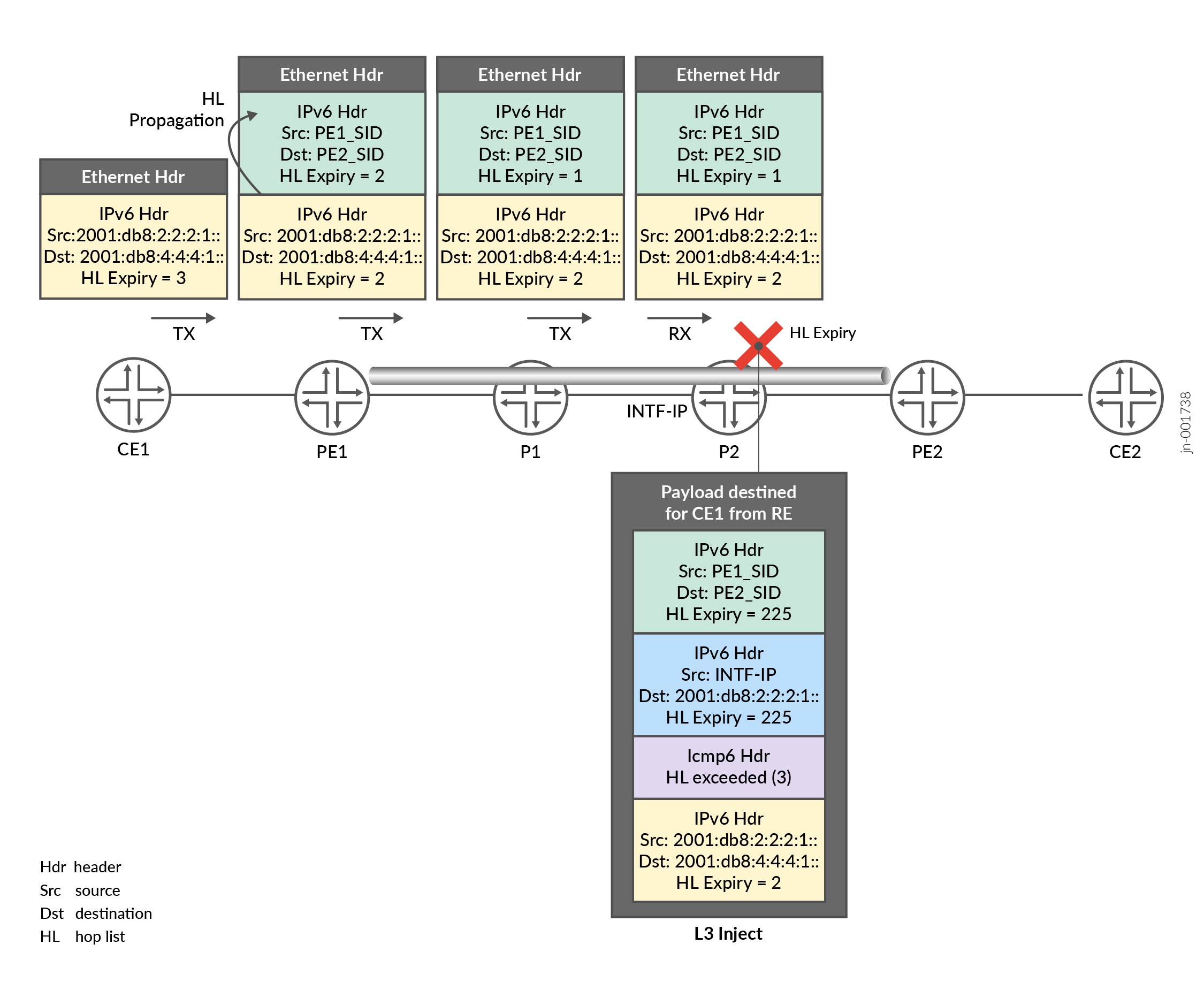
When the packet arrives at PE2, it decapsulates the packet, processing the inner IPv6 header. As the destination in the inner packet is CE1’s IP address, PE2 encapsulates it so it can be sent back to CE1. When PE1 receives the packet, it decapsulates the packet and processes the inner IPv6 header. The inner packet is then routed back to CE1. CE1 processes the hop-limit exceeded packet sourced from the P2 transit router.