Mapping Client and Server for Segment Routing to LDP Interoperability
Segment routing mapping server and client support enables interoperability between network islands that run LDP and segment routing (SR or SPRING). This interoperability is useful during a migration from LDP to SR. During the transition there can be islands (or domains) with devices that support either only LDP, or only segment routing. For these devices to interwork the LDP segment routing mapping server (SRMS) and segment routing mapping client (SRMC) functionality is required. You enable these server and client functions on a device in the segment routing network.
SR mapping server and client functionality is supported with either OSPF or IS-IS.
Overview of Segment Routing to LDP Interoperability
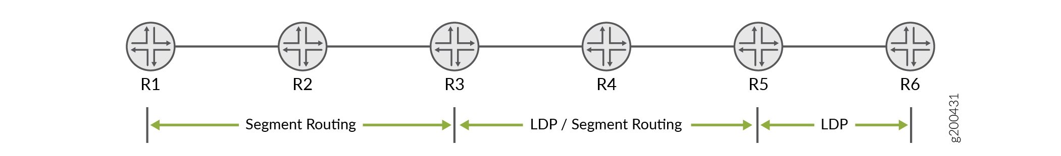
Figure 1 shows a simple LDP network topology to illustrate how interoperability of segment routing devices with LDP devices works. Keep in mind that both OSPF and IS-IS are supported, so for now we'll keep things agnostic with regard to the IGP. The sample topology has six devices, R1 through R6, in a network that is undergoing a migration from LDP to segment routing.
In the topology, devices R1, R2, and R3 are configured for segment routing only. Devices R5 and R6 are part of a legacy LDP domain and do not currently support SR. Device R4 supports both LDP and segment routing. The loopback addresses of all devices are shown. These loopbacks are advertised as egress FECs in the LDP domain and as SR node IDs in the SR domain. Interoperability is based on mapping a LDP FEC into a SR node ID, and vice versa.
For R1 to interwork with R6, both an LDP segment routing mapping server (SRMS) and a segment routing mapping client (SRMC) are needed. Its easier to understand the role of the SRMS and SRMC by looking at the traffic flow in a unidirectional manner. Based on Figure 1, we'll say that traffic flowing from left to right originates in the SR domain and terminates in the LDP domain. In like fashion, traffic that flows from right to left originates in the LDP domain and terminates in the SR domain.
The SRMS provides the information needed to stitch traffic in the left to right direction. The SRMC provides mapping for traffic that flows from right to left.
- Left to right Traffic Flow: The Segment Routing Mapping Server
The SRMS facilitates LSP stitching between the SR and LDP domains. The server maps LDP FECs into SR node IDs. You configure the LDP FECs to be mapped under the
[edit routing-options source-packet-routing]hierarchy level. Normally you need to map all LDP node loopback addresses for full connectivity. As shown below, you can map contiguous prefixes in a single range statement. If the LDP node loopbacks are not contiguous you need to define multiple mapping statements.You apply the SRMS mapping configuration under the
[edit protocols ospf]or[edit protocols isis]hierarchy level. This choice depends on which IGP is being used. Note that both the SR and LDP nodes share a common, single area/level, IGP routing domain.The SRMS generates an extended prefix list LSA (or LSP in the case of IS-IS). The information in this LSA allows the SR nodes to map LDP prefixes (FECs) to SR Node IDs. The mapped routes for the LDP prefixes are installed in the
inet.3andmpls.0routing tables of the SR nodes to facilitate LSP ingress and stitching operations for traffic in the left to right direction.The extended LSA (or LSP) is flooded throughout the (single) IGP area. This means you are free to place the SRMS configuration on any router in the SR domain. The SRMS node does not have to run LDP.
- Right to Left Traffic Flow: The Segment Routing Mapping Client
To interoperate in the right to left direction, that is, from the LDP island to the SR island, you simply enable segment routing mapping client functionality on a node that speaks both SR and LDP. In our example that is R4. You activate SRMC functionality with the
mapping-clientstatement at the[edit protocols ldp]hierarchy.The SRMC configuration automatically activates an LDP egress policy to advertise the SR domain's node and prefix SIDs as LDP egress FECs. This provides the LDP nodes with LSP reachability to the nodes in the SR domain.
- The SRMC function must be configured on a router that attaches to both the SR and LSP domains. If desired, the same node can also function as the SRMS.
Segment Routing to LDP Interoperability Using OSPF
Refer to Figure 1, assume that device R2 (in the segment routing network) is the SRMS.
-
Define the SRMS function:
[edit routing-options source-packet-routing ]
user@R2# set mapping-server-entry ospf-mapping-server prefix-segment-range ldp-lo0s start-prefix 192.168.0.5
user@R2# set mapping-server-entry ospf-mapping-server prefix-segment-range ldp-lo0s start-index 1000
user@R2# set mapping-server-entry ospf-mapping-server prefix-segment-range ldp-lo0s size 2
This configuration creates a mapping block for both the LDP device loopback addresses in the sample topology. The initial Segment ID (SID) index mapped to R5's loopback is
1000. Specifying size2results in SID index 10001 being mapped to R6's loopback address.Note:The IP address used as the
start-prefixis a loopback address of a device in the LDP network (R5, in this example). For full connectivity you must map all the loopback addresses of the LDP routers into the SR domain. If the loopback addresses are contiguous, you can do this with a singleprefix-segment-rangestatement. Non-contiguous loopbacks requires definition of multiple prefix mapping statements.Our example uses contiguous loopbacks so a single
prefix-segment-rangeis shown above. Here's an example of multiple mappings to support the case of two LDP nodes with non-contiguous loopback addressing:[edit routing-options source-packet-routing] show mapping-server-entry map-server-name { prefix-segment-range lo1 { start-prefix 192.168.0.5/32; start-index 1000; size 1; } prefix-segment-range lo2 { start-prefix 192.168.0.10/32; start-index 2000; size 1; } } } -
Next, configure OSPF support for the extended LSA used to flood the mapped prefixes.
[edit protocols]
user@R2# set ospf source-packet-routing mapping-server ospf-mapping-server
Once the mapping server configuration is committed on device R2, the extended prefix range TLV is flooded across the OSPF area. The devices capable of segment routing (R1, R2, and R3) install OSPF segment routing routes for the specified loopback address (R5 and R6 in this example), with a segment ID (SID) index. The SID index is also updated in the
mpls.0routing table by the segment routing devices. -
Enable SRMC functionality. For our sample topology you must enable SRMC functionality on R4.
[edit protocols]
user@R4# set ldp sr-mapping-client
Once the mapping client configuration is committed on device R4, the SR node IDs and label blocks are advertised as egress FECs to router R5, which then re-advertises them to R6.
Support for stitching segment routing and LDP next-hops with OSPF began in Junos OS 19.1R1.
Unsupported Features and Functionality for Segment Routing interoperability with LDP using OSPF
-
IPv6 prefixes are not supported.
-
Flooding of the OSPF Extended Prefix Opaque LSA across AS boundaries (inter-AS) is not supported.
-
Inter-area LDP mapping server functionality is not supported.
-
ABR functionality of Extended Prefix Opaque LSA is not supported.
-
ASBR functionality of Extended Prefix Opaque LSA is not supported.
-
The segment routing mapping server Preference TLV is not supported.
Interoperability of Segment Routing with LDP Using IS-IS
Refer to Figure 1, assume that device R2 (in the segment routing network) is the SRMS. The following configuration is added for the mapping function:
-
Define the SRMS function:
[edit routing-options source-packet-routing ]
user@R2# set mapping-server-entry isis-mapping-server prefix-segment-range ldp-lo0s start-prefix 192.168.0.5
user@R2# set mapping-server-entry isis-mapping-server prefix-segment-range ldp-lo0s start-index 1000
user@R2# set mapping-server-entry isis-mapping-server prefix-segment-range ldp-lo0s size 2
This configuration creates a mapping block for both the LDP device loopback addresses in the sample topology. The initial segment ID (SID) index mapped to R5's loopback is
1000. Specifying size2results in SID index 10001 being mapped to R6's loopback address.Note:The IP address used as the
start-prefixis a loopback address of a device in the LDP network (R5, in this example). For full connectivity you must map all the loopback addresses of the LDP routers in the SR domain. If the loopback addresses are contiguous, you can do this with aprefix-segment-rangestatement. Non-contiguous loopbacks require the definition of multiple mapping statements.Our example uses contiguous loopbacks so a single
prefix-segment-rangeis shown above. Here is an example of prefix mappings to handle the case of two LDP routers with non-contiguous loopback addressing:[edit routing-options source-packet-routing] show mapping-server-entry map-server-name { prefix-segment-range lo1 { start-prefix 192.168.0.5/32; start-index 1000; size 1; } prefix-segment-range lo2 { start-prefix 192.168.0.10/32; start-index 2000; size 1; } } } -
Next, configure IS-IS support for the extended LSP used to flood the mapped prefixes.
[edit protocols]
user@R2# set isis source-packet-routing mapping-server isis-mapping-server
Once the mapping server configuration is committed on device R2, the extended prefix range TLV is flooded across the OSPF area. The devices capable of segment routing (R1, R2, and R3) install IS-IS segment routing routes for the specified loopback address (R5 and R6 in this example), with a segment ID (SID) index. The SID index is also updated in the
mpls.0routing table by the segment routing devices. -
Enable SRMC functionality. For our sample topology you must enable SRMC functionality on R4.
[edit protocols]
user@R4# set ldp sr-mapping-client
Once the mapping client configuration is committed on device R4, the SR node IDs and label blocks are advertised as egress FECs to router R5, and from there on to R6.
Support for stitching segment routing and LDP next-hops with IS-IS began in Junos OS 17.4R1.
Unsupported Features and Functionality for Interoperability of Segment Routing with LDP using IS-IS
-
Penultimate-hop popping behavior for label binding TLV is not supported.
-
Advertising of range of prefixes in label binding TLV is not supported.
-
Segment Routing Conflict Resolution is not supported.
-
LDP traffic statistics does not work.
-
Nonstop active routing (NSR) and graceful Routing Engine switchover (GRES) is not supported.
-
IS-IS inter-level is not supported.
-
RFC 7794, IS-IS Prefix Attributes for Extended IPv4 is not supported.
-
Redistributing LDP route as a prefix-sid at the stitching node is not supported.