Example: Dynamic Endpoint Tunneling Configuration

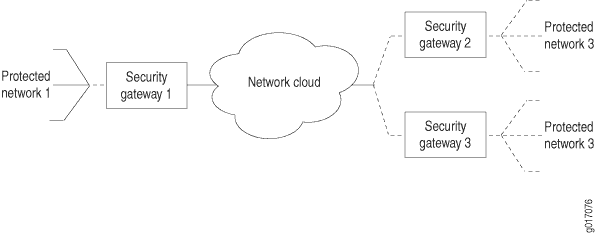
Figure 1 shows a local network N-1 located behind security gateway SG-1. SG-1 is a Juniper Networks router terminating dynamic peer endpoints. The tunnel termination address on SG-1 is 10.7.7.2 and the local network address is 172.16.1.0/24.
A remote peer router obtains addresses from an ISP pool and runs RFC-compliant IKE. Remote network N-2 has address 172.16.2.0/24 and is located behind security gateway SG-2 with tunnel termination address 10.7.7.1.
On Router SG-1, configure an IKE access profile to accept proposals from SG-2. Apply the interface identifier from the access profile to the inside services interface and apply the IKE access profile itself to the IPSec next-hop style service set.
Router SG-1
[edit]
access {
    profile ike_access {
                           client * { # Accepts proposals from specified peers that use the preshared key.
            ike {
                allowed-proxy-pair local 10.255.14.63/32 remote 10.255.14.64/32;
                pre-shared-key ascii-text "$ABC123"; # SECRET-DATA
                                     interface-id test_id; # Apply this ID to the inside services interfaces.
            }
        }
    }
}
interfaces {
    fe-0/0/0 {
        description "Connection to the local network";
        unit 0 {
            family inet {
                address 172.16.1.1/24;
            }
        }
    }
    so-1/0/0 {
        description "Connection to SG-2";
        no-keepalives;
        encapsulation cisco-hdlc;
        unit 0 {
            family inet {
                address 10.7.7.2/30;
            }
        }
    }
    sp-3/3/0 {
        unit 0 {
            family inet;
        }
        unit 3 {
            dial-options {
                                     ipsec-interface-id test_id; # Accepts dynamic endpoint tunnels.
                shared;
            }
            service-domain inside;
        }
        unit 4 {
            family inet;
            service-domain outside;
        }
    }
}
services {
                     service-set dynamic_nh_ss { # Create a next-hop service set
        next-hop-service { # for the dynamic endpoint tunnels.
            inside-service-interface sp-3/3/0.3;
            outside-service-interface sp-3/3/0.4;
        }
        ipsec-vpn-options {
            local-gateway 10.7.7.2;
                               ike-access-profile ike_access; # Apply the IKE access profile here.
        }
    }
}
Verifying Your Work
To verify proper operation of a dynamic endpoint tunnel configured on the AS PIC, use the following command:
show services ipsec-vpn ipsec security-associations (detail)
The following section shows output from this command used with the configuration example. The dynamically created rule _junos_ appears in the output, as well as the establishment of the inbound and outbound dynamically created tunnels.
user@router> show services ipsec-vpn ipsec security-associations detail
Service set: dynamic_nh_ss

  Rule:  _junos_ , Term: tunnel4, Tunnel index: 4
  Local gateway: 10.7.7.2, Remote gateway: 10.7.7.1
  Local identity: ipv4(any:0,[0..3]=10.255.14.63)
  Remote identity: ipv4(any:0,[0..3]=10.255.14.64)

    Direction: inbound , SPI: 428111023, AUX-SPI: 0
     Mode: tunnel, Type: dynamic, State: Installed
    Protocol: ESP, Authentication: hmac-sha1-96, Encryption: 3des-cbc
    Soft lifetime: Expires in 27660 seconds
    Hard lifetime: Expires in 27750 seconds
    Anti-replay service: Enabled, Replay window size: 64

    Direction: outbound , SPI: 4035429231, AUX-SPI: 0
     Mode: tunnel, Type: dynamic, State: Installed
    Protocol: ESP, Authentication: hmac-sha1-96, Encryption: 3des-cbc
    Soft lifetime: Expires in 27660 seconds
    Hard lifetime: Expires in 27750 seconds
    Anti-replay service: Enabled, Replay window size: 64
