ON THIS PAGE
Example: Configure IoT Device Discovery and Policy Enforcement
In this example, you'll configure your security device for IoT device discovery and security policy enforcement.
Overview
To get started with IoT device discovery in your network, all you need is a security device connected to Juniper ATP Cloud. Figure 1 shows the topology used in this example.
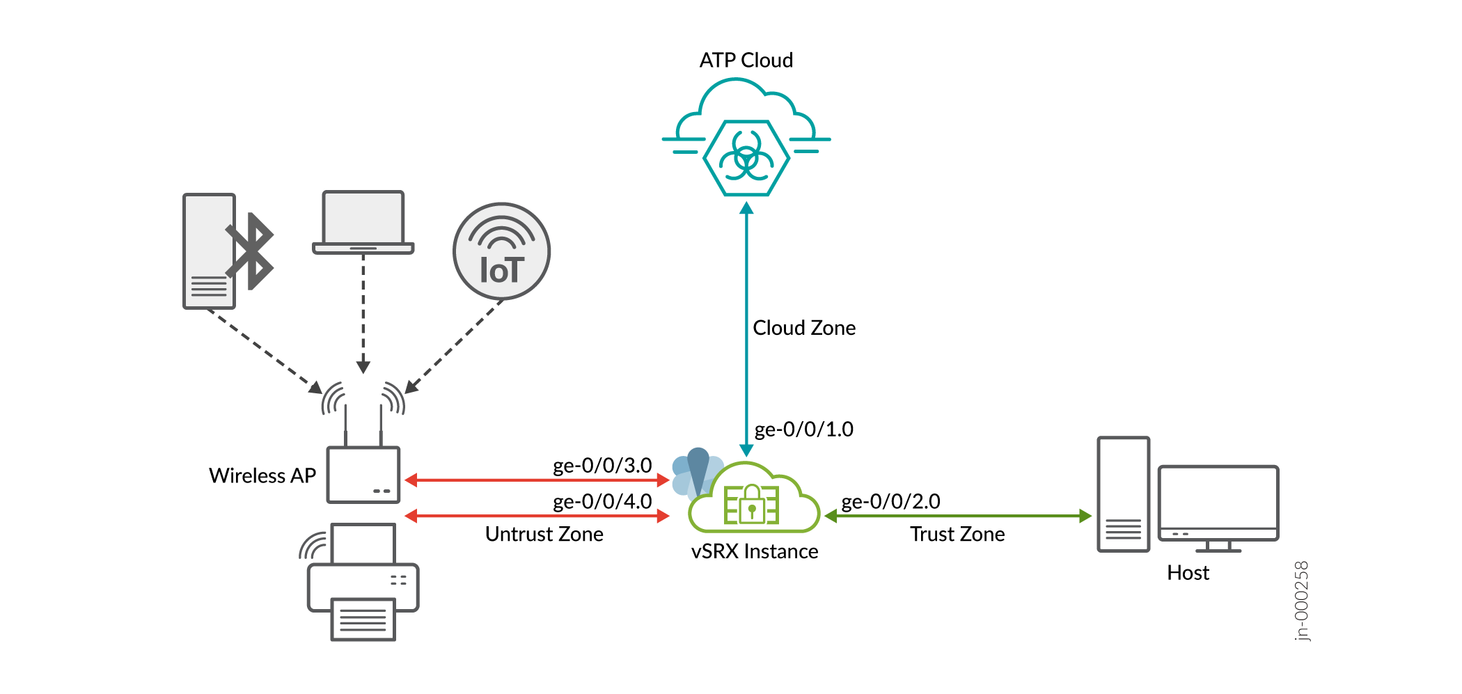
As shown in the topology, the network includes some IoT devices connected to an SRX Series Firewall through wireless access point (AP). The security device is connected to the Juniper Cloud ATP server, and to a host device.
The security device collects IoT device metadata and streams the relevant information to the Juniper ATP Cloud. To enable streaming of IoT metadata, you'll need to create security metadata streaming policies and attach these policies to security policies. Streaming of the IoT device traffic pauses automatically when Juniper Cloud server has sufficient details to classify the IoT device.
Juniper ATP cloud discovers and classifies IoT devices. Using the inventory of discovered IoT devices, you'll create threat feeds in the form of dynamic address groups. Once the security device downloads dynamic address groups, you can use the dynamic address groups to create and enforce security policies for the IoT traffic.
Table 1 and Table 2 provide details of the parameters used in this example.
| Zones | Interfaces | Connected To |
|---|---|---|
| trust | ge-0/0/2.0 | Client device |
| untrust | ge-0/0/4.0 and ge-0/0/3.0 | Access points to manage IoT traffic |
| cloud | ge-0/0/1.0 | Internet (to connect to Juniper ATP cloud) |
| Policy | Type | Application |
|---|---|---|
| P1 | Security policy | Allows traffic from trust zone to untrust zone |
| P2 | Security policy | Allows traffic from untrust zone to trust zone |
| P3 | Security policy | Allows traffic from trust zone to cloud zone |
| p1 | Metadata streaming Policy | Streams untrust zone to trust zone traffic metadata |
| p2 | Metadata streaming Policy | Streams trust zone to clod zone traffic metadata |
| Unwanted_Applications | Global Security Policy | Prevents IoT traffic based on the threat feed and security policy at global-context |
Requirements
- SRX Series Firewall or NFX Series device
- IoT security is a premium ATP feature and requires a premium license (Premium 1 or Premium 2) for entitlement. For details, check Software Licenses for ATP Cloud.
- Junos OS Release 22.1R1 or later
- Juniper Advanced Threat Prevention Cloud Account. See Registering a Juniper Advanced Threat Prevention Cloud Account.
We've verified and tested the configuration using a vSRX Virtual Firewall instance with Junos OS Release 22.1R1.
Configuration
Get Your SRX Series Firewall Ready to Work with Juniper ATP Cloud
You’ll need to configure your SRX Series Firewall to communicate with the Juniper ATP Cloud Web Portal. Ensure your SRX Series Firewall is connected to Internet. Ensure that you complete the following initial configuration to set your SRX Series Firewall to Internet.
- Configure the interface. In this example, we're using the interface
ge-0/0/1.0 as Internet-facing interface on SRX Series
Firewall.
[edit]
user@host# set interfaces ge-0/0/1 unit 0 family inet address 10.50.50.1/24
- Add the interface to a security zones.
[edit]
user@host# set security zones security-zone cloud interfaces ge-0/0/1.0 host-inbound-traffic system-services all
user@host# set security zones security-zone cloud interfaces ge-0/0/1.0 host-inbound-traffic protocols all
- Configure
DNS.
[edit]
user@host# set groups global system name-server 172.16.1.1
- Configure
NTP.
[edit]
user@host# set groups global system processes ntp enable
user@host# set groups global system ntp boot-server 192.168.1.20
user@host# set groups global system ntp server 192.168.1.20
Once your SRX Series can reach the Internet through the ge-0/0/1.0 interface, proceed with next steps.
- Check Required Licenses and Application Signature Package
- Enroll Security Device with Juniper ATP Cloud
- Configure IoT Traffic Streaming Settings
- Configure SRX Series Firewall
- Viewing Discovered IOT Devices in ATP Cloud
- Create Threat Feeds
- Create Security Policy Using Adaptive Threat Profiling Feeds
- Results
Check Required Licenses and Application Signature Package
- Ensure that you have an appropriate Juniper ATP cloud license. Use the
show system licensecommand to check the license status. The output might show the legacy ATP Cloud branding (SkyATP) based on the SRX device type (SRX or vSRX) and the JUNOS version as shown in the following samples:user@host> show system license License identifier: JUNOS123456 License version: 4 Software Serial Number: 1234567890 Customer ID: JuniperTest Features: Sky ATP - Sky ATP: Cloud Based Advanced Threat Prevention on SRX firewalls date-based, 2016-07-19 17:00:00 PDT - 2016-07-30 17:00:00 PDTroot@host> show system license License identifier: JUNOS123456 License version: 4 Software Serial Number: 1234567890 Customer ID: JuniperTest Features: ATP Cloud - Cloud Based Advanced Threat Prevention on SRX firewalls date-based, 2016-07-19 17:00:00 PDT - 2016-07-30 17:00:00 PDTNote:The
show system licensecommand on an SRX Series Firewall might not display an ATP Cloud license if the entitlement is managed in the cloud. This is because the SRX Series devices do not require an installed license key for ATP Cloud; instead, the entitlement is automatically transferred to the cloud server when you generate the license key using your SRX Series serial number and authorization code. For vSRX Virtual Firewalls, an installed license is required. - Ensure your device has the latest application signature pack on your
security device.
- Verify the application identification license is installed on your
device.
user@host> show system license
License usage:
Licenses Licenses Licenses Expiry
Feature name used installed needed
logical-system 4 1 3 permanent
License identifier: JUNOSXXXXXX
License version: 2
Valid for device: AA4XXXX005
Features:
appid-sig - APPID Signatur
- Download latest version of application signature
pack.
user@host> request services application-identification download
- Check the download
status.
user@host> request services application-identification download status
Downloading application package 3475 succeeded.
- Install the application identification signature
pack.
user@host> request services application-identification install
- Check the installed application signature pack version.
user@host> show services application-identification version
  Application package version: 3418
  Release date: Tue Sep 14 14:40:55 2021 UTC
- Verify the application identification license is installed on your
device.
Enroll Security Device with Juniper ATP Cloud
Lets start with enrolling the security device with Juniper ATP cloud. If you've already enrolled your device, you can skip this step and jump directly to Configure IoT Traffic Streaming Settings. If not, use one of the following method for device enrollment.
- Method 1: Enrolling Security Device Using CLI
- Method 2: Enrolling Security Device in Juniper ATP Cloud Web Portal
Method 1: Enrolling Security Device Using CLI
- On your SRX Series Firewall, run the following command to initiate the
enrollment
process.
user@host> request services advanced-anti-malware enroll
Please select geographical region from the list:
1. North America
2. European Region
3. Canada
4. Asia Pacific
Your choice: 1
- Select an existing realm or create a new
realm.
Enroll SRX to:
1. A new SkyATP security realm (you will be required to create it first)
2. An existing SkyATP security realm
Select option 1 to create a realm. Use the following steps:
-
You are going to create a new Sky ATP realm, please provide the required information:
-
Please enter a realm name (This should be a name that is meaningful to your organization. A realm name can only contain alphanumeric characters and the dash symbol. Once a realm is created, it cannot be changed):

Real name: example-company-a
-
Please enter your company name:
Company name: Example Company A
-
Please enter your e-mail address. This will be your username for your Sky ATP account:
Email: me@example-company-a.com
-
Please setup a password for your new Sky ATP account (It must be at least 8 characters long and include both uppercase and lowercase letters, at least one number, at least one special character):
Password: **********
Verify: **********
-
Please review the information you have provided:
Region: North America
New Realm: example-company-a
Company name: Example Company A
Email: me@example-company-a.com
-
Create a new realm with the above information? [yes,no]
yes
Device enrolled successfully!
You can also use an existing realm for enrolling your SRX Series with Juniper ATP Cloud.
-
- Use the
show services advanced-anti-malwarestatus CLI command to confirm that your SRX Series Firewall is connected to the cloud server.root@idpreg-iot-v2# run show services advanced-anti-malware dynamic-filter status Feb 09 18:36:46 Dynamic Filter Server Connection Status: Server Hostname: srxapi.us-west-2.sky.junipersecurity.net Server Port: 443 Proxy Hostname: None Proxy Port: None Control Plane Connection Status: Connected Last Successful Connect: 2022-02-09 18:36:07 PST Pkts Sent: 2 Pkts Received: 6
Method 2: Enrolling Security Device in Juniper ATP Cloud Web Portal
You can use a Junos OS operation (op) script to configure your SRX Series Firewall to connect to the Juniper Advanced Threat Prevention Cloud service.
- On Juniper ATP Cloud Web portal, click the Enroll button on the Devices page.
- Copy the command to your clipboard and click OK.
- Paste the command into the Junos OS CLI of the SRX Series Firewall in operational mode.
- Use the
show services advanced-anti-malwarestatus command to verify that a connection is made to the cloud server from the SRX Series Firewall. The server host name in the following sample is an example only.user@host> show services advanced-anti-malware statusServer connection status: Server hostname: srxapi.us-west-2.sky.junipersecurity.net Server realm: qatest Server port: 443 Proxy hostname: None Proxy port: None Control Plane: Connection time: 2022-02-15 21:31:03 PST Connection status: Connected Service Plane: fpc0 Connection active number: 18 Connection retry statistics: 48In the sample, the connection status indicates that the cloud server is connected to your security device.
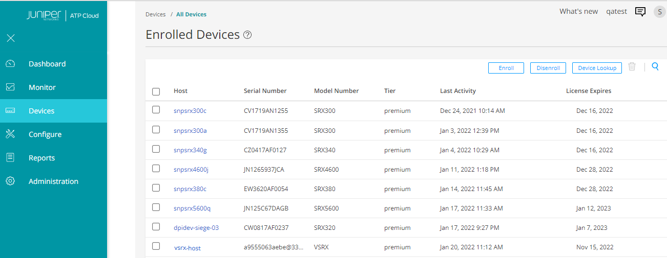
- You can also view the enrolled devices in Juniper ATP Cloud portal. Go
to Devices > All Devices page. The page lists
all the enrolled devices.
Configure IoT Traffic Streaming Settings
In this procedure, you'll create metadata streaming policies and enable security services on your security device.
- Complete cloud connection configuration.
[edit]
user@host# set services security-intelligence url https://cloudfeeds.sky.junipersecurity.net/api/manifest.xml
user@host# set services security-intelligence authentication tls-profile aamw-ssl
-
Create a security metadata streaming policy.
[edit]
user@host# set services security-metadata-streaming policy p1 dynamic-filter
user@host# set services security-metadata-streaming policy p2 dynamic-filter
We'll later attach these security metadata streaming policy to security policies to enable the IoT traffic streaming for the session.
- Enable security services such as application tracking, application
identification, and
PKI.
[edit]
user@host# set services application-identification
user@host# set security pki
user@host# set security application-tracking
Configure SRX Series Firewall
Use this procedure to configure interfaces, zones, policies enable IoT packet filtering and streaming services on your security device.
-
Configure interfaces.
[edit]
user@host# set interfaces ge-0/0/2 mtu 9092
user@host# set interfaces ge-0/0/2 unit 0 family inet address 10.60.60.1/24
user@host# set interfaces ge-0/0/3 mtu 9092
user@host# set interfaces ge-0/0/3 unit 0 family inet address 10.70.70.1/24
user@host# set interfaces ge-0/0/4 mtu 9092
user@host# set interfaces ge-0/0/4 unit 0 family inet address 10.80.80.1/24
-
Configure security zones and enable application traffic for each configured zone.
[edit]
user@host# set security zones security-zone trust interfaces ge-0/0/2.0 host-inbound-traffic system-services all
user@host# set security zones security-zone trust interfaces ge-0/0/2.0 host-inbound-traffic protocols all
user@host# set security zones security-zone trust application-tracking
user@host# set security zones security-zone untrust interfaces ge-0/0/4.0 host-inbound-traffic system-services all
user@host# set security zones security-zone untrust interfaces ge-0/0/4.0 host-inbound-traffic protocols all
user@host# set security zones security-zone untrust interfaces ge-0/0/3.0 host-inbound-traffic system-services all
user@host# set security zones security-zone untrust interfaces ge-0/0/3.0 host-inbound-traffic protocols all
user@host# set security zones security-zone untrust application-tracking
user@host# set security zones security-zone cloud application-tracking
As shown in the topology, the untrust zone receives transit and host-bound traffic from IOT devices in network. The client device is in trust zone and the Juniper ATP Cloud is in cloud zone.
-
Configure security policy P1.
[edit]
user@host# set security policies from-zone trust to-zone untrust policy P1 match source-address any
user@host# set security policies from-zone trust to-zone untrust policy P1 match destination-address any
user@host# set security policies from-zone trust to-zone untrust policy P1 match application any
user@host# set security policies from-zone trust to-zone untrust policy P1 then permit
This configuration allows traffic from trust zone to untrust zone.
-
Configure security policy P2.
[edit]
user@host# set security policies from-zone untrust to-zone trust policy P2 match source-address any
user@host# set security policies from-zone untrust to-zone trust policy P2 match destination-address any
user@host# set security policies from-zone untrust to-zone trust policy P2 match application any
user@host# set security policies from-zone untrust to-zone trust policy P2 then permit
user@host# set security policies from-zone untrust to-zone trust application-services security-metadata-streaming-policy p1
The configuration allows traffic from untrust zone to trust zone and applies the security metadata streaming policy p1 to enable IoT traffic streaming for the session.
-
Configure security policy P3.
[edit]
user@host# set security policies from-zone trust to-zone cloud policy P3 match source-address any
user@host# set security policies from-zone trust to-zone cloud policy P3 match destination-address any
user@host# set security policies from-zone trust to-zone cloud policy P3 match application any
user@host# set security policies from-zone trust to-zone cloud policy P3 then permit
user@host# set security policies from-zone trust to-zone cloud application-services security-metadata-streaming-policy p2
This configuration allows traffic from trust zone to cloud zone and applies the security metadata streaming policy p2 to enable IoT traffic streaming for the session.
- Commit the configuration.
[edit]
user@host# commit
Lets check all the discovered IoT devices in Juniper ATP Cloud portal.
Viewing Discovered IOT Devices in ATP Cloud
To view discovered IoT devices in Juniper ATP Cloud portal, navigate to Minotor > IoT Devices page.
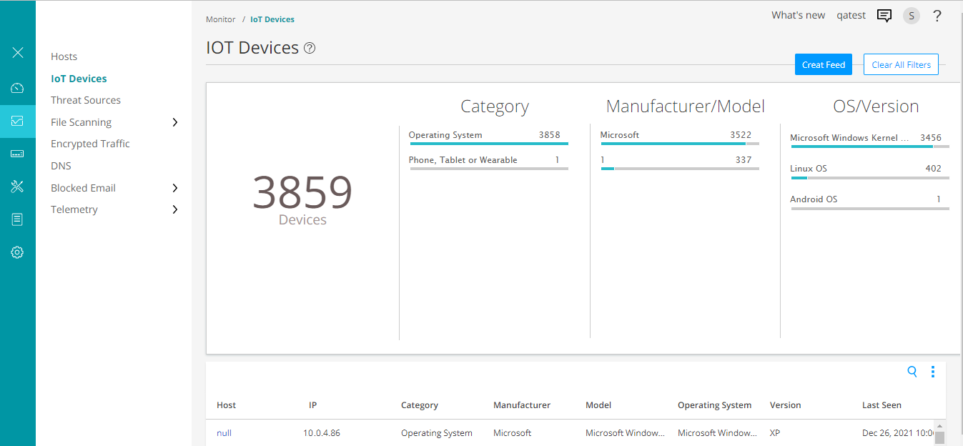
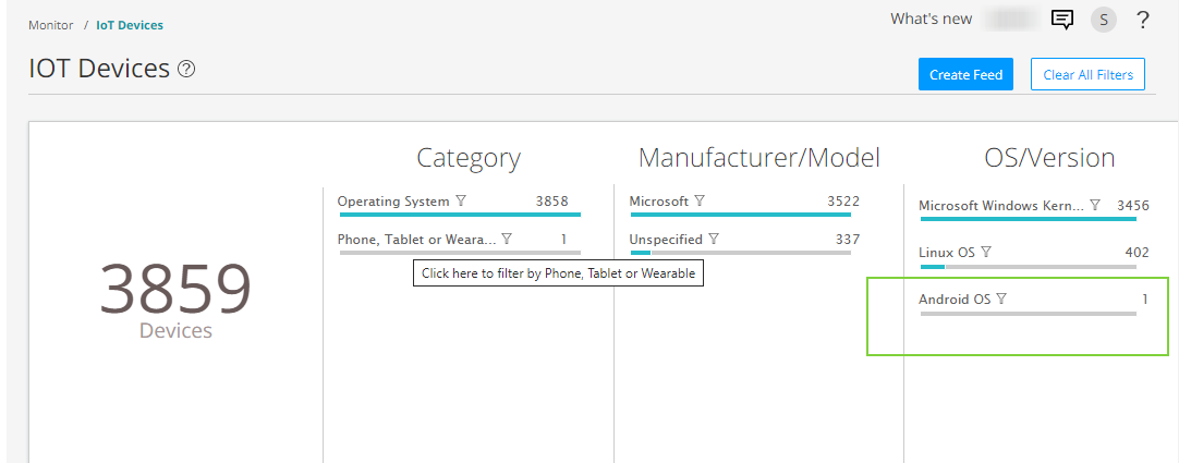
You can click and filter the IoT devices based on device category, manufacturer, type of operating system.
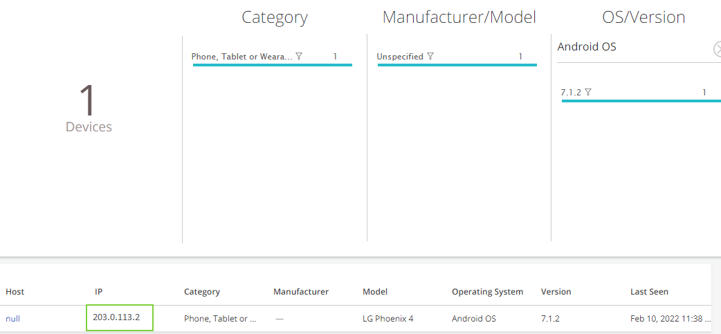
The page lists IoT devices with details such as IP address, type, manufacturer, models, and so on. Using these details, you can monitor and create threat feeds to enforce security policy.
Create Threat Feeds
Once Juniper ATP Cloud identifies IoT devices, you can create threat feeds. When your security device downloads threat feeds in the form of dynamic address groups, you can use the feed your security policies to take enforcement actions on the inbound and outbound traffic on these IoT devices.
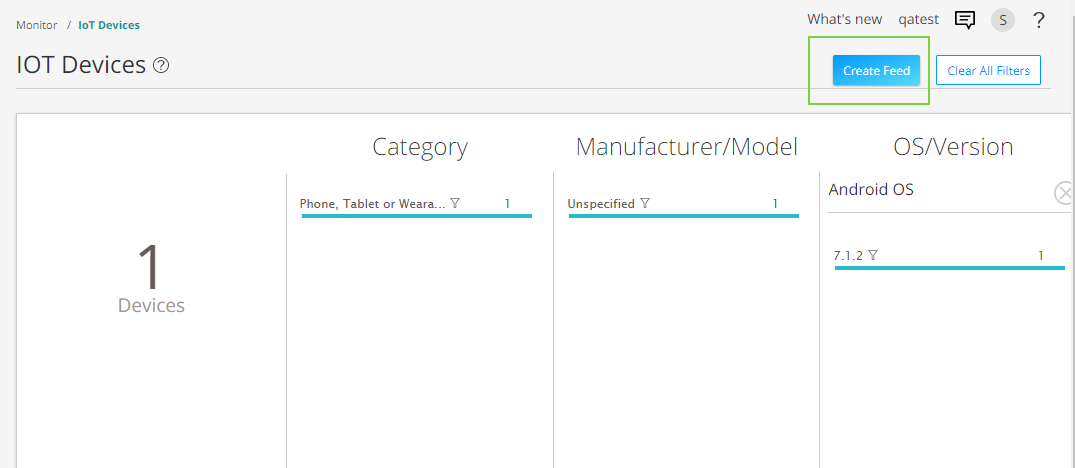
- Go to Minotor > IoT Devices page and click
Create Feeds option.
-
Click the plus sign (+). The Add New Feed page appears.
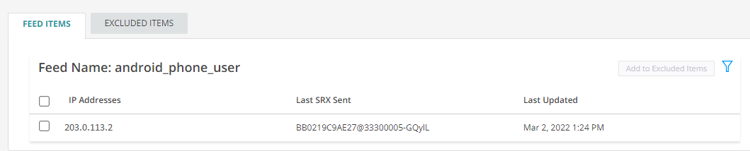
In this example, we will use the feed name android_phone_user with a time-to-live (TTL) of seven days.
Complete the configuration for the following fields: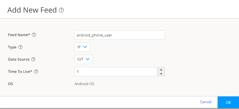
-
Feed Name:
Enter a unique name for the threat feed. The feed name must begin with an alpha-numeric character and can include letters, numbers, and underscores; no spaces are allowed. The length is 8–63 characters.
-
Type: Select the content type of the feed as IP.
-
Data Source: Select the data source for creating the feed as IOT.
-
Time to Live: Enter the number of days for the required feed entry to be active. After the feed entry crosses the time to live (TTL) value, the feed entry is automatically removed. The available range is 1–365 days.
-
- Click OK to save the changes.
- Go to Configure > Adaptive Threat Profiling. The
page displays all threat feeds created. You can see the threat feed
android_phone_user listed on the page.
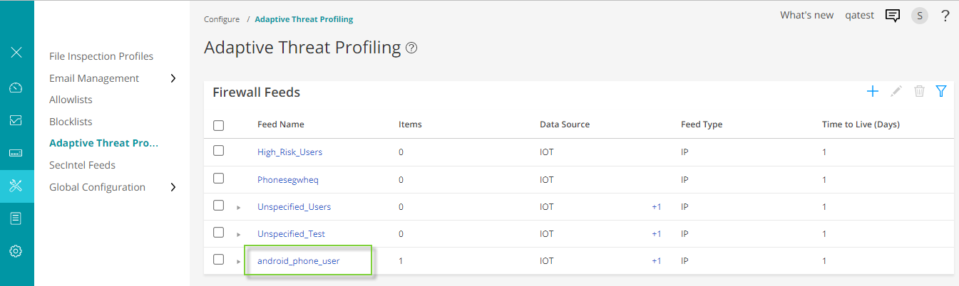
Click on the threat feed to display the IP address included in the threat feed.
- Ensure that your security device has downloaded the feed. Downloading
happens automatically at regular intervals but can take a few minutes.
user@host> show services security-intelligence sec-profiling-feed status
Category name            :SecProfiling
  Feed name              :Android_Phone_User
    Feed type            :IP
    Last post time       :N/A
    Last post status code:N/A
    Last post status     :N/A
  Feed name              :IT_feed
    Feed type            :IP
    Last post time       :N/A
    Last post status code:N/A
    Last post status     :N/A
  Feed name              :High_Risk_Users
    Feed type            :IP
    Last post time       :N/A
    Last post status code:N/A
    Last post status     :N/A
You can manually download the threat feeds using the following command:
request services security-intelligence download status ||match android_phone_user
Lets proceed with creating security policies with the downloaded threat feeds.
Create Security Policy Using Adaptive Threat Profiling Feeds
Once your security device downloads the threat feed, you can refer it as dynamic address group in a security policy. A dynamic address is a group of IP addresses of IoT devices belonging to a specific domain.
In this example, we create a policy that detects traffic from android phones and blocks the traffic.
- Define security policy match
criteria.
[edit]
user@host# set security policies global policy Block_Android_Traffic match source-address android_phone_user
user@host# set security policies global policy Block_Android_Traffic match destination-address any
user@host# set security policies global policy Block_Android_Traffic match application any
- Define security policy
action.
[edit]
user@host# set security policies global policy Block_Android_Traffic then deny
In this example, when you commit the configuration, your security device blocks HTTP traffic for the IoT devices belonging to the specific domain.
For more information, see Configure Adaptive Threat Profiling.
Results
From configuration mode, confirm your configuration by entering the show security command. If the output does not display the intended configuration, repeat the configuration instructions in this example to correct it.
               [edit]


               user@host# show security policies
from-zone trust to-zone untrust {
    policy P1 {
        match {
            source-address any;
            destination-address any;
            application any;
        }
        then {
            permit;
        }
    }
}
from-zone untrust to-zone trust {
    policy P2 {
        match {
            source-address any;
            destination-address any;
            application any;
        }
        then {
            permit;
        }
    }
    application-services {
        security-metadata-streaming-policy p1;
    }
}
from-zone trust to-zone cloud {
    policy P3 {
        match {
            source-address any;
            destination-address any;
            application any;
        }
        then {
            permit;
        }
    }
    application-services {
        security-metadata-streaming-policy p2;
    }
}
user@host# show security policies global
policy Block_Android_Traffic {
    match {
        source-address android_phone_user;
        destination-address any;
        application any;
    }
    then {
        deny;
    }
}
Check security zones.
               [edit]


               user@host# show security zones
security-zone trust {
    interfaces {
        ge-0/0/2.0 {
            host-inbound-traffic {
                system-services {
                    all;
                }
                protocols {
                    all;
                }
            }
        }
    }
    application-tracking;
}
security-zone untrust {
    interfaces {
        ge-0/0/4.0 {
            host-inbound-traffic {
                system-services {
                    all;
                }
                protocols {
                    all;
                }
            }
        }
        ge-0/0/3.0 {
            host-inbound-traffic {
                system-services {
                    all;
                }
                protocols {
                    all;
                }
            }
        }
    }
    application-tracking;
}
security-zone cloud {
    interfaces {
        ge-0/0/0.1 {
            host-inbound-traffic {
                system-services {
                    all;
                }
                protocols {
                    all;
                }
            }
        }
    }
    application-tracking;
}
show services
               [edit]


               user@host# show services
advanced-anti-malware {
    dynamic-filter {
        traceoptions {
            file dyn-filterd-log size 1g world-readable;
            level all;
            flag all;
        }
    }
    connection {
        url https://srxapi.us-west-2.sky.junipersecurity.net;
        authentication {
            tls-profile aamw-ssl;
        }
    }
}
ssl {
    initiation {
        profile aamw-ssl {
            trusted-ca [ aamw-secintel-ca aamw-cloud-ca ];
            client-certificate aamw-srx-cert;
            actions {
                crl {
                    disable;
                }
            }
        }
    }
}
security-metadata-streaming {
    policy p1 {
        dynamic-filter;
    }
    policy p2 {
        dynamic-filter;
    }
}
security-intelligence {
    url https://cloudfeeds.sky.junipersecurity.net/api/manifest.xml;
    authentication {
        tls-profile aamw-ssl;
    }
}
If you are done configuring the feature on your device, enter commit from configuration mode.
Verification
Check Feed Summary and Status
Purpose: Verify if your security device is receiving IP address feeds in the form of dynamic address groups.
Action: Run the following command:
               user@host> show services advanced-anti-malware dynamic-filter status
Dynamic Filter Server Connection Status:
  Server Hostname: srxapi.us-west-2.sky.junipersecurity.net
  Server Port: 443
  Proxy Hostname: None
  Proxy Port: None
  Control Plane
    Connection Status: Connected
    Last Successful Connect: 2022-02-12 09:51:50 PST
    Pkts Sent: 3
    Pkts Received: 42
Meaning The output displays the connection status and other details of the Juniper ATP Cloud server.