Example: Configuring Remote Port Mirroring on PTX Routers
This example shows you how to configure and verify remote port mirroring on PTX platforms running Junos Evolved. The PTX platforms include PTX10001-36MR, LC1201 and LC1202 in PTX10004, PTX10008 and PTX10016 chassis.
Before You Begin
| Hardware and Software requirements | Junos OS Evolved Release 22.2R1.12-EVO or later. PTX10001-36MR See Feature Explorer for a complete listing of supported platforms and Junos OS versions. |
|
Estimated reading time |
Fifteen minutes. |
|
Estimated configuration time |
Thirty minutes |
|
Business impact |
Port mirror is a critical tool for debugging and security related tasks. Mirrored traffic can be analyzed offline by a variety of tools to analyze protocol interactions, anomaly detection, or lawful intercept wire tap operations. |
|
Know more |
To better understand Port Mirroring, see Port Mirroring and Analyzers |
|
Learn more |
Learning Portal |
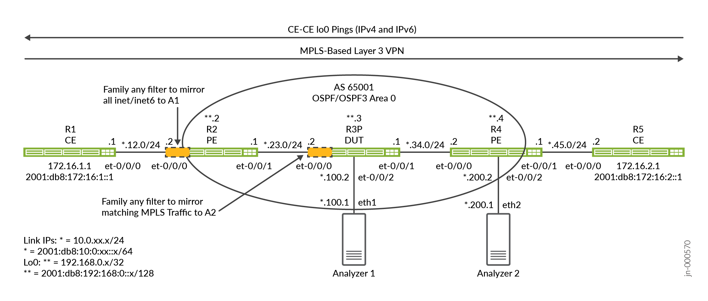
Functional Overview
Remote Port Mirroring Functional Overview provides a quick summary of the protocols and technologies deployed in this example.
|
Routing and Signaling protocols |
|
|
OSPF and OSPF3 |
All routers run OSPF and OSPF3 as the IGP. All provider routers belong to area 0 (also called the backbone area). The OSPF/OSPF3 routing domains provide internal reachability to all networks and interfaces in the topology. The CE routers use OSPF and OSPF3 to exchange routes with the PEs. |
| MPLS and RSVP | The provider routers signal MPLS LSPs using the RSVP protocol. IPv6 tunneling is enabled to support IPv6 over MPLS. MPLS is used to support a Layer 3 VPN. |
| MP-BGP | Multiprotocol BGP is used between the PE routers to advertise customer VPN routes. |
| Layer 3 VPN | The PE routers use a VRF routing instance to support as Layer 3 VPN serve for the CE routers. The customer traffic is transported over the core inside of RSVP signaled LSPs. For more details on the operational of a MPLS-Based L3 VPN, see Example: Configure a Basic MPLS-Based Layer 3 VPN. |
|
Routed Protocols |
|
|
IPv4 and IPv6 |
All routers are configured to support routing of both IPv4 and IPv6. |
|
Analyzer (monitoring station) |
|
|
Centos and Wireshark |
The analyzer runs Centos 7.x with a GUI version of Wireshark. |
Topology Overview
This example uses the context of a MPLS-based L3 VPN to demonstrate the remote port mirroring feature on PTX routers. The L3 VPN is configured to support both IPv4 and IPv6 traffic between the customer edge (CE) and provider edge (PE) routers.
| Router Name |
Role |
Function |
| CE | Customer Edge (CE) router that sends test traffic to confirm port mirroring works properly. | These routers are designated as CE routers. The CE routers obtain L3 VPN service from the provider network. The CEs don't share the same OSPF routing domain as the provider routers. |
| PE | Provider Edge (PE) router attached to the CE. | The PEs are found at the edge of a provider network. Our PEs support Layer 3
VPNs through the use of routing instances, MP-BGP, RSVP, and an MPLS data plane.
The PE1 router functions as one of the remote port mirroring DUTs. |
| P | A Provider (P) core router. | The P router represents a BGP-free provider core router. It supports OSPF,
OSPF3, and MPLS transport. It does not run BGP or carry VPN state. The P router functions as one of the remote port mirroring DUTs. |
| Analyzer | The analyzer device receives the mirror traffic for storage and analysis. | The specifics of the analyzer are outside the scope of this document. There are a number of open source and commercial options available. Our analyzer happens to be running Centos 7.x with a Gnome desktop supporting a GUI version of Wireshark. |
Topology Illustrations
This example demonstrates two ways of mirroring CE traffic sent over the provider network:
-
The first method uses a match-all filter on the PE-CE VRF interface.
-
The second method demonstrates a MPLS label matching filter that is applied on the provider (P) router.
The PE1 router (R2) and the P router (R3) are the routers where remote port mirroring is
configured and function as our DUTs. These routers use family any firewall
filters to match on select traffic for port mirroring. A combination of ingress and egress
filters are employed to mirror both request and response traffic flowing between the CE
routers (R1 and R5) .
Remote port mirroring uses a tunnel for GRE encapsulation to send mirrored traffic to a remote analyzer device. Our topology has two analyzers. One is attached to the R2/PE1 router and the other to the R3/P router. This allows us to demonstrate two ways of mirroring CE traffic, one at a PE and the other on a core P router. We use a Centos host with Wireshark for packet capture and analysis.
PTX platforms use the Flexible Tunnel Interface (fti) infrastructure to support variety of tunneling applications. In the case of remote port mirrors, GRE tunnels are configured on fti interfaces to transport mirrored traffic to a remote analyzer device . As part of this example, you'll configure fti based GRE tunnels, a mirroring instance, and the firewall filters that select traffic to be mirrored.
R2/PE1 Configuration Steps
For information about navigating the CLI, see Using the CLI Editor in Configuration Mode
For complete configuration on all routers see: Appendix 2: Set Commands on All Routers
This section highlights the configuration tasks needed to configure the PE1/R2 router in this example. We provide full configurations for all routers in the appendix. Step 1 summarizes the example's baseline. This baseline consists of IPv4 and IPv6 connectivity, MPLS, and a Layer 3 VPN. Our example places the focus on configuring and verifying remote port mirroring.
For details on the L3 VPN operation and baseline configuration see Example: Configure a Basic MPLS-Based Layer 3 VPN.
-
Configure the IP routing and L3 VPN baseline on the PE1 router. This involves the following:
-
Numbering the interfaces for both IPv4 and IPv6 and including
family
                  mpls
support on core facing interfaces. -
Configuring the OSPF and OSPFv3 routing protocols to provide reachability between all network interfaces.
-
RSVP and MPLS label switched paths (LSPs) to support L3 VPN traffic.
-
Configuring VRF and BGP peering with the
inet-vpnandinet6-vpn[edit] set interfaces et-0/0/0 unit 0 family inet address 10.0.12.2/24 set interfaces et-0/0/0 unit 0 family inet6 address 2001:db8:10:0:12::2/64 set interfaces et-0/0/1 unit 0 family inet address 10.0.23.1/24 set interfaces et-0/0/1 unit 0 family inet6 address 2001:db8:10:0:23::1/64 set interfaces et-0/0/1 unit 0 family mpls set interfaces lo0 unit 0 family inet address 192.168.0.2/32 set interfaces lo0 unit 0 family inet6 address 2001:db8:192:168:0::2/128 set policy-options policy-statement ospf-export term 1 from protocol bgp set policy-options policy-statement ospf-export term 1 then accept set routing-instances ce1 instance-type vrf set routing-instances ce1 protocols ospf area 0.0.0.0 interface all set routing-instances ce1 protocols ospf export ospf-export set routing-instances ce1 protocols ospf3 area 0.0.0.0 interface all set routing-instances ce1 protocols ospf3 export ospf-export set routing-instances ce1 interface et-0/0/0.0 set routing-instances ce1 route-distinguisher 65001:1 set routing-instances ce1 vrf-target target:65001:100 set routing-instances ce1 vrf-table-label set routing-options router-id 192.168.0.2 set routing-options autonomous-system 65001 set protocols bgp group ibgp type internal set protocols bgp group ibgp local-address 192.168.0.2 set protocols bgp group ibgp family inet unicast set protocols bgp group ibgp family inet-vpn unicast set protocols bgp group ibgp family inet6-vpn unicast set protocols bgp group ibgp neighbor 192.168.0.4 set protocols mpls label-switched-path pe2 to 192.168.0.4 set protocols mpls label-switched-path pe2 no-cspf set protocols mpls ipv6-tunneling set protocols mpls interface all set protocols mpls interface fxp0.0 disable set protocols ospf area 0.0.0.0 interface all set protocols ospf area 0.0.0.0 interface fxp0.0 disable set protocols ospf3 area 0.0.0.0 interface all set protocols ospf3 area 0.0.0.0 interface fxp0.0 disable set protocols rsvp interface all set protocols rsvp interface fxp0 disable
With the baseline covered the remaining steps focus on configuring the R2/PE1 router to port mirror all traffic sent and received on its CE1 facing VRF interface.
-
- You begin with configuration of the GRE tunnel. On a PTX router the tunnel is
implemented over an fti interface. The source address for the GRE tunnel does not have to
be routable, unless you expect to perform diagnostic ping testing sourced from or destined
to the GRE tunnel source. The GRE destination for traffic mirrored by PE1 is the analyzer
1 router. This destination must be reachable for mirror traffic to be sent to the
analyzer. We use a passive IGP instance to ensure IGP reachability to the analyzer
networks.
The destination address maps to the Analyzer 1 device attached to the et-0/0/2 interface on the P/R3 router. You must configure the fti logical interface with
family cccto support remote port mirroring on the PTX. This is because the mirror action occurs at Layer 2.set interfaces fti0 unit 1 description "GRE tunnel for remote port mirror" set interfaces fti0 unit 1 tunnel encapsulation gre source address 10.100.0.1 set interfaces fti0 unit 1 tunnel encapsulation gre destination address 10.0.100.1 set interfaces fti0 unit 1 family ccc
Note:A passive IGP instance is provisioned for the interfaces attached to the analyzer devices. This provides IGP reachability to the analyzer ports for the GRE encapsulated mirrored traffic. The passive setting prevents the generation of hello packets to the analyzers as this would just clutter up the captures.
In addition, we configured a static route on the analyzer device to allow it to respond to pings as an aid in diagnostic testing. Strictly speaking, only simplex connectivity or routing is needed between the DUTs and the analyzer for remote port mirroring to function.
- Configure the sampling instance. We use a rate of 1 to sample all matching packets. The
default
run-lengthof 1 is left in place given all matching traffic is already sampled. You must specify the logical interface on the fti router that is used to transport the mirror traffic. You configuredunit 1on the fti0 interface for the GRE tunnel in the previous step, so that same interface and unit is specified as the output interface in the mirror instance.[edit] set forwarding-options port-mirroring instance pe-mirror input rate 1 set forwarding-options port-mirroring instance pe-mirror family any output interface fti0.1
Note:You can specify a maximum packet length for mirrored traffic at the
[edit
                forwarding-options port-mirroring
                instance
                  instance-name
                input]
hierarchy with themaximum-packet-lengthoption. By default the packet length is 0, which means the entire packet is mirrored. -
Define two family
anyfirewall filters to match on and mirror the CE traffic. Two filters are defined, one for mirroring CE1 to CE2 traffic, and the other for mirroring CE2 to CE1. The filters include a count function to assist in verification. The port mirror action directs matching traffic to the port mirroring instance you configured previously.Family
anyfilters support both Layer 2 and Layer 3 matching. For the former, you can match on VLAN ID, interface, MAC address, or MPLS label. For the latter, you can match on standard IPv4 or IPv6 headers fields.Given our topology we use a match all term that catches all traffic sent or received by the CEs. This includes IPv4, IPv6, ARP, LLDP, and any routing protocols such as OSPF.
[edit]
set firewall family any filter ce1-ce2 term mirror-ce1-ce2 then count ce1-ce2-mirror
set firewall family any filter ce1-ce2 term mirror-ce1-ce2 then port-mirror-instance pe-mirror
set firewall family any filter ce1-ce2 term mirror-ce1-ce2 then accept
set firewall family any filter ce1-ce2 term else then accept

set firewall family any filter ce2-ce1 term mirror-ce2-ce1 then count ce2-ce1-mirror
set firewall family any filter ce2-ce1 term mirror-ce2-ce1 then port-mirror-instance pe-mirror
set firewall family any filter ce2-ce1 term mirror-ce2-ce1 then accept
set firewall family any filter ce2-ce1 term else then accept
Both filters end with a match all accept term to override the default deny all action at the end of a Junos filter. In this way traffic that is not matched in the first term is accepted. This term is added as a safeguard in the event that later a specific match condition is added to the first term.
If desired, you can evoke a policer action in your filter to limit the number of mirrored packets sent over the GRE tunnel. The policer is defined with a bandwidth and burst limit along with a discard action for traffic that exceeds the policer.
You cannot apply a PM filter with a policer action in the egress direction.Note:If you wanted to match only ICMP traffic sent between the IPv4 loopback addresses of the CE devices add Layer 3 match criteria to your filter.
set firewall family any filter ce1-ce2 term mirror-ce1-ce2 from ip-version ipv4 ip-protocol icmp
set firewall family any filter ce1-ce2 term mirror-ce1-ce2 from ip-version ipv4 ip-source-address 172.16.1.1/32
set firewall family any filter ce1-ce2 term mirror-ce1-ce2 from ip-version ipv4 ip-destination-address 172.16.2.1/32
set firewall family any filter ce1-ce2 term mirror-ce1-ce2 then count ce1-ce2-mirror
set firewall family any filter ce1-ce2 term mirror-ce1-ce2 then port-mirror-instance pe-mirror
set firewall family any filter ce1-ce2 term mirror-ce1-ce2 then accept
set firewall family any filter ce1-ce2 term else then accept
-
Apply the filters to the CE facing interface on R2/PE1. For our example, that means application of the filters to the et-0/0/0 interface on PE1. Note the directionality of the filter application. An ingress and egress filter is needed to mirror both directions of CE traffic flow.
[edit]
set interfaces et-0/0/0 unit 0 filter input ce1-ce2
set interfaces et-0/0/0 unit 0 filter output ce2-ce1
For completeness we show the configuration of R2/PE1 in curly brace format.
system {
    host-name r2-ptx;
}
interfaces {
    et-0/0/0 {
        unit 0 {
            filter {
                input ce1-ce2;
                output ce2-ce1;
            }
            family inet {
                address 10.0.12.2/24;
            }
            family inet6 {
                address 2001:db8:10:0:12::2/64;
            }
        }
    }
    et-0/0/1 {
        unit 0 {
            family inet {
                address 10.0.23.1/24;
            }
            family inet6 {
                address 2001:db8:10:0:23::1/64;
            }
            family mpls;
        }
    }
    fti0 {
        unit 1 {
            description "GRE tunnel for remote port mirror";
            tunnel {
                encapsulation gre {
                    source {
                        address 10.100.0.1;
                    }
                    destination {
                        address 10.0.100.1;
                    }
                }
            }
            family ccc;
        }
    }
    lo0 {
        unit 0 {
            family inet {
                address 192.168.0.2/32;
            }
            family inet6 {
                address 2001:db8:192:168:0::2/128;
            }
        }
    }
}
forwarding-options {
    port-mirroring {
        instance {
            pe-mirror {
                input {
                    rate 1;
                }
                family any {
                    output {
                        interface fti0.1;
                    }
                }
            }
        }
    }
}
policy-options {
    policy-statement ospf-export {
        term 1 {
            from protocol bgp;
            then accept;
        }
    }
}
firewall {
    family any {
        filter ce1-ce2 {
            term mirror-ce1-ce2 {
                then {
                    count ce1-ce2-mirror;
                    port-mirror-instance pe-mirror;
                    accept;
                }
            }
        }
        filter ce2-ce1 {
            term mirror-ce2-ce1 {
                then {
                    count ce2-ce1-mirror;
                    port-mirror-instance pe-mirror;
                    accept;
                }
            }
        }
    }
}
routing-instances {
    ce1 {
        instance-type vrf;
        protocols {
            ospf {
                area 0.0.0.0 {
                    interface all;
                }
                export ospf-export;
            }
            ospf3 {
                area 0.0.0.0 {
                    interface all;
                }
                export ospf-export;
            }
        }
        interface et-0/0/0.0;
        route-distinguisher 65001:1;
        vrf-target target:65001:100;
        vrf-table-label;
    }
}
routing-options {
    router-id 192.168.0.2;
    autonomous-system 65001;
}
protocols {
    bgp {
        group ibgp {
            type internal;
            local-address 192.168.0.2;
            family inet {
                unicast;
            }
            family inet-vpn {
                unicast;
            }
            family inet6-vpn {
                unicast;
            }
            neighbor 192.168.0.4;
        }
    }
    mpls {
        label-switched-path pe2 {
            to 192.168.0.4;
            no-cspf;
        }
        ipv6-tunneling;
        interface all;
        interface fxp0.0 {
            disable;
        }
    }
    ospf {
        area 0.0.0.0 {
            interface all;
            interface fxp0.0 {
                disable;
            }
        }
    }

    ospf3 {
        area 0.0.0.0 {
            interface all;
            interface fxp0.0 {
                disable;
            }
            interface et-0/0/2.0 {
                passive;
            }
        }
    }
    rsvp {
        interface all;
    }
}
R3 Configuration Steps
For information about navigating the CLI, see Using the CLI Editor in Configuration Mode
For complete configuration on all routers see: Appendix 2: Set Commands on All Routers
This section highlights the main configuration tasks needed to configure the P/R3 router in this example. We start with the MPLS-based L3 VPN baseline. Then, we show the steps needed to configure remote port mirroring on a P router to match on and mirror MPLS traffic.
-
Configure the IPv4 and IPv6 routing and MPLS baseline on the P/R3 router. This involves a few things:
-
Numbering the interfaces for both IPv4 and IPv6 and including
family
                  mpls
support on core facing interfaces. -
Configure the OSPF and OSPFv3 routing protocols to provide reachability between all network interfaces.
-
RSVP and MPLS to support the L3 VPN data plane. As a P router, BGP peering and VRF definitions are not present.
[edit]
set interfaces et-0/0/0 description "R3-R2 P-PE"
set interfaces et-0/0/0 unit 0 family inet address 10.0.23.2/24
set interfaces et-0/0/0 unit 0 family inet6 address 2001:db8:10:0:23::2/64
set interfaces et-0/0/0 unit 0 family mpls
set interfaces et-0/0/1 unit 0 family inet address 10.0.34.1/24
set interfaces et-0/0/1 unit 0 family inet6 address 2001:db8:10:0:34::1/64
set interfaces et-0/0/1 unit 0 family mpls
set interfaces et-0/0/2 unit 0 family inet address 10.0.100.2/24
set interfaces lo0 unit 0 family inet address 192.168.0.3/32
set interfaces lo0 unit 0 family inet6 address 2001:db8:192:168:0::3/128

set routing-options router-id 192.168.0.3

set protocols mpls interface all
set protocols mpls interface fxp0.0 disable
set protocols mpls interface et-0/0/2.0 disable

set protocols ospf area 0.0.0.0 interface all
set protocols ospf area 0.0.0.0 interface fxp0.0 disable
set protocols ospf area 0.0.0.0 interface et-0/0/2.0 passive

set protocols ospf3 area 0.0.0.0 interface all
set protocols ospf3 area 0.0.0.0 interface fxp0.0 disable
set protocols ospf3 area 0.0.0.0 interface et-0/0/2.0 passive

set protocols rsvp interface all
set protocols rsvp interface fxp0 disable
set protocols rsvp interface et-0/02.0 disable
The P1/R3 router attaches to Analyzer 1 over the et-0/0/2 interface. We disable the RSVP protocol and MPLS support on this interface as the mirrored traffic arrives as IPv4 using GRE encapsulation. LSPs don't extend to the analyzer.
Note:The et-0/0/2 interface configuration used here assumes that the analyzer replies to ARP and ND request sent by the DUT for MAC address resolution. If this is not the case, or if you wish that ARP traffic is not part of your packet captures, you should configure a static ARP entry. Be sure to specify the correct MAC address for the interface on the analyzer device that is attached to the DUT.
With the baseline covered, the following steps focus on configuring remote port mirroring for MPLS traffic on a P router.
-
- You begin with the definition of the GRE tunnel. On PTX platforms tunnels are
implemented on an fti interface. The source address for the GRE
tunnel does not have to be routable, unless you expect to perform diagnostic ping testing
sourced from or destined to the GRE tunnel source. The GRE destination for mirrored
traffic is the Analyzer 2 device attached to PE2/R4. This destination must be reachable
for mirror traffic to be sent to the analyzer. We use a passive IGP instance to ensure IGP
reachability to the analyzer networks.
You must configure the fti logical interface with
family cccto support remote port mirroring on the PTX. This is because the mirror action occurs at Layer 2.[edit] set interfaces fti0 unit 1 tunnel encapsulation gre source address 10.100.0.3 set interfaces fti0 unit 1 tunnel encapsulation gre destination address 10.0.200.1 set interfaces fti0 unit 1 family ccc
Note:A passive IGP instance is provisioned for the interfaces attached to the analyzer devices. This provides IGP reachability to the analyzer ports for the GRE encapsulated mirrored traffic. The passive setting prevents the generation of hello packets to the analyzers as this would just clutter up the packet captures.
In addition, we configured a static route on the analyzer device so it can respond to pings as an aid in diagnostic testing. Strictly speaking, only simplex connectivity or routing is needed between the DUTs and the analyzer for remote port mirroring to function.
- Configure the sampling instance. We use a rate of 1 to select and sample all matching
packets. By default the
run-lengthis 1. This is fine given all matching traffic is sampled with a rate of 1. You must specify the logical interface on the fti router that is used to send the mirror traffic. You configured unit 1 for the fti interface in the previous step so that same unit is specified as the output interface for the mirror instance.[edit] set forwarding-options port-mirroring instance p-router-mirror input rate 1 set forwarding-options port-mirroring instance p-router-mirror family any output interface fti0.1
-
Define the firewall filters to mirror traffic sent between the CE routers.
Family
anyfilters only allow Layer 2 match types. For example, VLAN ID, interface, MAC address, or MPLS label. As a result you are not able to use IPv4 or IPv4 specific match conditions.Two filters are defined, one for each direction of traffic flow between the CEs.
Given our goal of mirroring VPN traffic at a P router, the filters are written to match on the specific labels that identify MPLS traffic flows between the two PE routers.
For the CE1 to CE2 direction, the filter matches on the RSVP transport label used by PE1 to reach PE2. Because of PHP and egress application, the filter used in the CE2 to CE1 direction matches on the VRF label advertised by PE1 to PE2. Matching traffic evokes the port mirror action to the mirroring instances defined previously. The filters include a count function to assist in confirmation of proper operation.
We determined the correct labels using these commands:
-
For traffic sent by CE1 to CE2, the current RSVP transport label is displayed with a
show rsvp session ingress detailcommand. This is the RSVP assigned label used by PE1 to reach PE2 using MPLS. It should be noted that all VPN traffic sent between this PE pair uses the same RSVP transport. The resulting filter is not specific to the CE1 VRF on the PE router.user@r2-ptx> show rsvp session ingress detail Ingress RSVP: 1 sessions 192.168.0.4 From: 192.168.0.2, LSPstate: Up, ActiveRoute: 0 LSPname: pe2, LSPpath: Primary LSPtype: Static Configured Suggested label received: -, Suggested label sent: - Recovery label received: -, Recovery label sent: 22 Resv style: 1 FF, Label in: -, Label out: 22 Time left: -, Since: Tue Apr 18 12:58:47 2023 Tspec: rate 0bps size 0bps peak Infbps m 20 M 1500 Port number: sender 2 receiver 65196 protocol 0 PATH rcvfrom: localclient Adspec: sent MTU 1500 Path MTU: received 1500 PATH sentto: 10.0.23.2 (et-0/0/1.0) 1 pkts RESV rcvfrom: 10.0.23.2 (et-0/0/1.0) 1 pkts, Entropy label: Yes Record route: <self> 10.0.23.2 10.0.34.2 Total 1 displayed, Up 1, Down 0
In this case the output shows that RSVP label 22 is assigned to the PE1/R2 router to reach the LSP egress at the PE2/R4 router.
-
For traffic sent by CE2 to CE1 you must match on the VRF label. This is because the P router is the penultimate hop node and on the egress interface it will have popped the RSVP transport label. This leaves on the VRF label as the bottom of the stack. You confirm the VRF label advertised by PE1 to the PE2 with a
show route
                  advertising-protocol bgp remote-peer-address detail
command. This command shows the routes advertised by the local PE along with the VRF label that is bound to the routing instance.user@r2-ptx> show route advertising-protocol bgp 192.168.0.4 detail ce1.inet.0: 7 destinations, 8 routes (7 active, 0 holddown, 0 hidden) * 10.0.12.0/24 (1 entry, 1 announced) BGP group ibgp type Internal Route Distinguisher: 65001:1 VPN Label: 16 Nexthop: Self Flags: Nexthop Change Localpref: 100 AS path: [65001] I Communities: target:65001:100 * 172.16.1.1/32 (1 entry, 1 announced) BGP group ibgp type Internal Route Distinguisher: 65001:1 VPN Label: 16 Nexthop: Self Flags: Nexthop Change MED: 1 Localpref: 100 AS path: [65001] I Communities: target:65001:100 rte-type:0.0.0.0:1:0 . . .The output shows that PE1 signaled VRF label 16 to the PE2 router for the routes associated with the CE1 routing instance.
Using the information from the previous commands we know which RSVP/VRF labels to match on in the firewall filter.
[edit]
set firewall family any filter ce1-ce2 term ce1-ce2-mirror from mpls-label 22
set firewall family any filter ce1-ce2 term ce1-ce2-mirror then count ce1-ce2-traffic
set firewall family any filter ce1-ce2 term ce1-ce2-mirror then port-mirror-instance p-router-mirror
set firewall family any filter ce1-ce2 term else then accept

set firewall family any filter ce2-ce1 term ce2-ce1-mirror from mpls-label 16
set firewall family any filter ce2-ce1 term ce2-ce1-mirror then count ce2-ce1-traffic
set firewall family any filter ce2-ce1 term ce2-ce1-mirror then port-mirror-instance p-router-mirror
set firewall family any filter ce2-ce1 term else then accept
The filters end with a match all accept term to override the default deny all at the end of a Junos filter. In this way traffic that is not matched in the first term is accepted. This is critical to avoiding disrupting all other traffic using this interface!
Note:RSVP labels can change due to LSP re-signaling caused by link outages or other configuration changes. We demonstrate how a filter can be used to match on specific labels to help constrain the traffic that is mirrored. You can always apply a match all filter to ensure that MPLS label changes does not affect mirroring. The disadvantage of the match all approach is you will mirror all traffic received on the P router interface to include the core protocols and non-VPN traffic.
-
-
Apply the filters to the PE1 facing interface on the P/R3 router. The directionality of the filter application is important. Our filters are designed to operate in the input direction for CE1 to CE2 traffic, and in the egress direction for CE2 to CE1 traffic. Because these are family any filters, they are applied at the unit level independent of either IPv4 or IPv6. Family any filters operate at Layer 2 which is independent of any protocol family.
[edit]
set interfaces et-0/0/0 unit 0 filter input ce1-ce2
set interfaces et-0/0/0 unit 0 filter output ce2-ce1
For completeness we show the configuration of R2/PE1 in curly brace format.
system {
    host-name r3-ptx;
}
interfaces {
    et-0/0/0 {
        description "R3-R2 P-PE";
        unit 0 {
            filter {
                input ce1-ce2;
                output ce2-ce1;
            }
            family inet {
                address 10.0.23.2/24;
            }
            family inet6 {
                address 2001:db8:10:0:23::2/64;
            }
            family mpls;
        }
    }
    et-0/0/1 {
        unit 0 {
            family inet {
                address 10.0.34.1/24;
            }
            family inet6 {
                address 2001:db8:10:0:34::1/64;
            }
            family mpls;
        }
    }
    et-0/0/2 {
        unit 0 {
            family inet {
                address 10.0.100.2/24;
            }
        }
    }
    fti0 {
        unit 1 {
            tunnel {
                encapsulation gre {
                    source {
                        address 10.100.0.3;
                    }
                    destination {
                        address 10.0.200.1;
                    }
                }
            }
            family ccc;
        }
    }
    lo0 {
        unit 0 {
            family inet {
                address 192.168.0.3/32;
            }
            family inet6 {
                address 2001:db8:192:168:0::3/128;
            }
        }
    }
}
forwarding-options {
    port-mirroring {
        instance {
            p-router-mirror {
                input {
                    rate 1;
                }
                family any {
                    output {
                        interface fti0.1;
                    }
                }
            }
        }
    }
}
firewall {
    family any {
        filter ce1-ce2 {
            term ce1-ce2-mirror {
                from {
                    mpls-label 22;
                }
                then {
                    count ce1-ce2-traffic;
                    port-mirror-instance p-router-mirror;
                }
            }
            term else {
                then accept;
            }
        }
        filter ce2-ce1 {
            term ce2-ce1-mirror {
                from {
                    mpls-label 16;
                }
                then {
                    count ce2-ce1-traffic;
                    port-mirror-instance p-router-mirror;
                }
            }
            term else {
                then accept;
            }
        }
    }
}
routing-options {
    router-id 192.168.0.3;
}
protocols {
    mpls {
        interface all;
        interface fxp0.0 {
            disable;
        }
        interface et-0/0/2.0 {
            disable;
        }
    }
    ospf {
        area 0.0.0.0 {
            interface all;
            interface fxp0.0 {
                disable;
            }
            interface et-0/0/2.0 {
                passive;
            }
        }
    }
    ospf3 {
        area 0.0.0.0 {
            interface all;
            interface fxp0.0 {
                disable;
            }
            interface et-0/0/2.0 {
                passive;
            }
        }
    }
    rsvp {
        interface all;
        interface et-0/0/2.0 {
            disable;
        }
    }
}
Verification
In this example, there are two DUTs where port mirroring is configured. The verification mechanisms are the same. In both cases you'll confirm that the filter is matching on expected traffic, and that mirrored packets are sent to the associated analyzer.
With our configuration PE mirrored traffic is sent to Analyzer 1 while P router mirrored traffic is sent to Analyzer 2. If desired all mirrored traffic can be sent to the same destination but, this results in the interspersing of traffic if port mirroring occurs in multiple places simultaneously.
These steps can be performed on either or both of the DUT routers as desired. R2/PE1 is the first DUT and the P router/R3 is the second.
-
Confirm OSPF and OSPF3 neighbors and routes to all loopback addresses. Also, verify the route to the remote analyzer IP address. You must be able to send IPv4 packets to the remote analyzer. Optionally, the analyzer can be configured with static routes so it can reply.
user@r2-ptx> show ospf neighbor

Address          Interface              State           ID               Pri  Dead
10.0.23.2        et-0/0/1.0             Full            192.168.0.3      128    36

user@r2-ptx> show ospf3 neighbor

ID               Interface              State     Pri   Dead
192.168.0.3      et-0/0/1.0             Full      128     36
  Neighbor-address fe80::569e:18ff:fe45:ffff


user@r2-ptx> show route protocol ospf | match /32
192.168.0.3/32     *[OSPF/10] 2d 22:41:49, metric 1
192.168.0.4/32     *[OSPF/10] 2d 22:41:49, metric 2
224.0.0.5/32       *[OSPF/10] 2d 22:43:37, metric 1
172.16.1.1/32      *[OSPF/10] 2d 22:41:45, metric 1
224.0.0.5/32       *[OSPF/10] 2d 22:43:37, metric 1

user@r2-ptx> show route protocol ospf3 | match /128
2001:db8:192:168::3/128
2001:db8:192:168::4/128
ff02::5/128        *[OSPF3/10] 2d 22:47:10, metric 1
2001:db8:172:16:1::1/128
ff02::5/128        *[OSPF3/10] 2d 21:38:06, metric 1
Note:In the above output, the 172.16.1.1/32 route is learned in the
ce1routing instance. Thus, with this command you have confirmed proper OSPF operation in both the core and customer edge! Only the local CE1 loopback is listed because the remote CE loopback is learned as a BGP route.The passive IGP instance configured on the interface connected to the analyzers provided the needed IP connectivity. Again, we add static routes to the analyzers to permit return traffic for diagnostic testing.
user@r2-ptx> show route 10.0.100.1 inet.0: 15 destinations, 15 routes (15 active, 0 holddown, 0 hidden) + = Active Route, - = Last Active, * = Both 10.0.100.0/24 *[OSPF/10] 2d 22:49:10, metric 2 > to 10.0.23.2 via et-0/0/1.0 user@r2-ptx> show route 10.0.200.1 inet.0: 15 destinations, 15 routes (15 active, 0 holddown, 0 hidden) + = Active Route, - = Last Active, * = Both 10.0.200.0/24 *[OSPF/10] 1d 20:36:13, metric 3 > to 10.0.23.2 via et-0/0/1.0 user@r2-ptx> ping 10.0.100.1 count 2 PING 10.0.100.1 (10.0.100.1) 56(84) bytes of data. 64 bytes from 10.0.100.1: icmp_seq=1 ttl=63 time=5.48 ms 64 bytes from 10.0.100.1: icmp_seq=2 ttl=63 time=4.91 ms --- 10.0.100.1 ping statistics --- 2 packets transmitted, 2 received, 0% packet loss, time 1002ms rtt min/avg/max/mdev = 4.908/5.196/5.484/0.288 ms -
Confirm fti interface and GRE tunnel status.
user@r2-ptx> show interfaces fti0.1 detail
  Logical interface fti0.1 (Index 1000) (SNMP ifIndex 543) (Generation 609885357005)
    Description: GRE tunnel for remote port mirror
    Flags: Up Point-To-Point Encapsulation: GRE DF
          , Source address: 10.100.0.1/32, Destination address: 10.0.100.1
  Traffic statistics:
   Input  bytes  :                    0
   Output bytes  :             12887342
   Input  packets:                    0
   Output packets:                99020
    Local statistics:
     Input  bytes  :                    0
     Output bytes  :                    0
     Input  packets:                    0
     Output packets:                    0
    Transit statistics:
     Input  bytes  :                    0                    0 bps
     Output bytes  :             12887342                    0 bps
     Input  packets:                    0                    0 pps
     Output packets:                99020                    0 pps
    Protocol ccc, MTU: 1476, Generation: 609885357006, Route table: 0
      Flags: Is-Primary
The highlights in the output indicate the tunnel interface and GRE tunnel are operational. The non-0 output packet counter is a good sign that traffic is being mirrored. We don't expect any input packets as this GRE tunnel is used only to send mirrored traffic to a remote analyzer.
-
Confirm the port mirroring instance. The port mirroring state should be
up, and the correct mirroring interface should be listed under the destination. The familyanyindicates this a Layer 2 port mirror instance that is protocol family agnostic. Mirrored traffic includes the original Layer 2 frame along with its contents.user@r2-ptx> show forwarding-options port-mirroring Instance Name: pe-mirror Instance Id: 1 Input parameters: Rate : 1 Run-length : 1 Maximum-packet-length : 0 Output parameters: Family State Destination Next-hop any up fti0.1 NA -
Clear the firewall counters and interface statistics on the DUT. Then generate a known number of IPv4 and IPv6 test packets between the CE router loopback addresses.
user@r2-ptx> clear firewall all
user@r2-ptx> clear interfaces statistics all
user@r1-ptx> ping 172.16.2.1 source 172.16.1.1 count 4
PING 172.16.2.1 (172.16.2.1) from 172.16.1.1 : 56(84) bytes of data.
64 bytes from 172.16.2.1: icmp_seq=1 ttl=61 time=1237 ms
64 bytes from 172.16.2.1: icmp_seq=2 ttl=61 time=178 ms
64 bytes from 172.16.2.1: icmp_seq=3 ttl=61 time=507 ms
64 bytes from 172.16.2.1: icmp_seq=4 ttl=61 time=417 ms

--- 172.16.2.1 ping statistics ---
4 packets transmitted, 4 received, 0% packet loss, time 3066ms
rtt min/avg/max/mdev = 177.830/584.676/1237.435/395.575 ms, pipe 2

user@r1-ptx> ping 2001:db8:172:16:2::1 source 2001:db8:172:16:1::1 count 4
64 bytes from 2001:db8:172:16:2::1: icmp_seq=1 ttl=62 time=978 ms
64 bytes from 2001:db8:172:16:2::1: icmp_seq=2 ttl=62 time=621 ms
64 bytes from 2001:db8:172:16:2::1: icmp_seq=3 ttl=62 time=782 ms
64 bytes from 2001:db8:172:16:2::1: icmp_seq=4 ttl=62 time=920 ms

--- 2001:db8:172:16:2::1 ping statistics ---
4 packets transmitted, 4 received, 0% packet loss, time 2999ms
rtt min/avg/max/mdev = 621.122/825.114/978.021/137.715 ms
-
Back on R2/PE1, display firewall counters and interface statistics to confirm they reflect the test traffic. You may see some extra packets counted in the CE1 to CE 2 direction that reflect the OSPF, OSPF3, or ARP exchanges between the CE12 and PE1 routers. Note that in the CE12 to CE1 direction the filter application in the egress direction only catches end-to-end traffic. Therefore the CE2-CE1 counter does reflect the test traffic generated.
user@r2-ptx> show firewall

Filter: ce1-ce2
Counters:
Name                                                                            Bytes              Packets
ce1-ce2-mirror                                                                   1353                   13

Filter: ce2-ce1
Counters:
Name                                                                            Bytes              Packets
ce2-ce1-mirror                                                                   752                    8
Display interface statistics for the fti0./1 interface used to mirror traffic to the remote analyzer.
user@r3-ptx> show interfaces fti0.1 detail
  Logical interface fti0.1 (Index 1000) (SNMP ifIndex 543) (Generation 609885357005)
    Description: GRE tunnel for remote port mirror
    Flags: Up Point-To-Point Encapsulation: GRE DF
          , Source address: 10.100.0.1/32, Destination address: 10.0.100.1
  Traffic statistics:
   Input  bytes  :                    0
   Output bytes  :                 2424
   Input  packets:                    0
   Output packets:                   20
    Local statistics:
     Input  bytes  :                    0
     Output bytes  :                    0
     Input  packets:                    0
     Output packets:                    0
    Transit statistics:
     Input  bytes  :                    0                    0 bps
     Output bytes  :                 2424                 2096 bps
     Input  packets:                    0                    0 pps
     Output packets:                   20                    2 pps
    Protocol ccc, MTU: 1476, Generation: 609885357006, Route table: 0
      Flags: Is-Primary
With 8 test packets generated you may be surprised to see a packet count on the egress of the fti0.1 interface of 20. First, recall that both OSPF and OSPF3 hellos packets sent by the CE1 router are being mirrored. Second, consider that both ping request and replies are being mirrored at PE1/R2. That means there are 8 ping request, and 8 replies, for a total of 16 ICMP test packets.
-
Run tcpdump or the analysis application of your choice on the monitoring station to confirm receipt and processing of the mirrored test traffic. Our setup has two analyzer devices, or precisely, one analyzer host with two interfaces. You can perform this step on both of the analyzer interfaces simultaneously, if desired. Recall that the traffic mirrored to the eth2 interface on Analyzer 2 is mirrored at the P router/R3, and therefore includes MPLS encapsulation. Traffic mirrored from R1/PE1 does not include the MPLS encapsulation.
We begin with a capture on the eth1 interface that receives mirrored traffic from R2/PE1. After starting the capture we perform a single IPv4 ping between the CE routers.
Note:After the capture, we pasted the text-based tcpdump output into a text application that displays line numbers. This makes it easier to call out key portions of the capture. We also enabled line wrap to improve visibility.
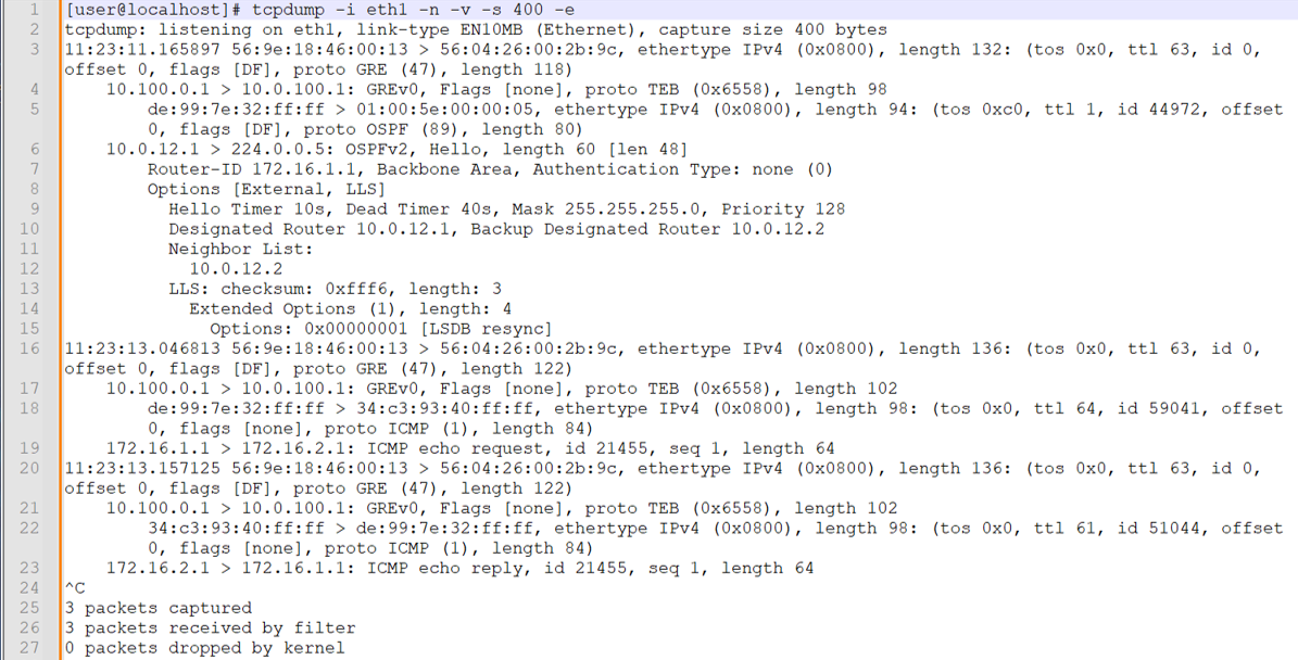
Areas to note in the capture include:
-
We evoke tcpdump on the eth1 interface and include flags to prevent name resolution, provide detail, capture up to 400 bytes, and to include Layer 2 headers.
-
Line 3 is the start of the first Layer 2 frame and IP packet. The Ethernet frame is the encapsulation used by the R3/P1 router to send traffic to the locally attached analyzer device. The destination MAC address is owned by the eth1 interface on Analyzer 1. The 100.0.100.1 IP to MAC address resolution is performed through ARP. The Ethernet frame indicates it carries the IP protocol. At the IP layer we see the packet has the Don’t Fragment bit set and identifies that the payload is GRE.
-
Line 4 shows the decode of the outer IP packet and its GRE payload. The source and destination IP addresses reflect the GRE tunnel configured ion the fti0.1 interface at R2/PE1. The GRE header identifies that its payload is a Layer 2 frame via the transparent Ethernet bridging (TEB) protocol ID. This confirms that remote port mirroring on PTX platforms with a family
anyfilter results in the mirroring of Layer 2 frames. -
Line 5 is the decode for the GRE packet's payload . The source and destination MAC addresses (de:99:7e:32:ff:ff and 01:00:5e:00:00:05, respectively) reflect those used for OSPF hello multicast at the link layer. Line 5 also shows that the payload of the GRE encapsulated Layer 2 frame is IP, and that the payload of the IP packet is OSPF.
Note:The OSPF hello exchange between CE and PE is local in a Layer 3 VPN. We see the OSPF packets sent by the local CE because the port mirror action at ingress captured all traffic. The OSPF hello packets generated by the remote CE are not transported over the core and therefore not seen as egress in the capture.
-
Line 6 decodes the OSPF hello sent by the CE1 router. The source IP address is assigned to the et-0/0/0.0 interface of CE1. The destination IP address is used for OSPF multicast.
-
We skip over the OSPF decode and land on line 16. This is the second frame in the capture and reflects an IPv4 ICMP echo request. Once again, the Layer 2 frame reflects the MAC addresses of the P1/R3 and Analyzer 1 devices. We see that the outer frame carries an IP packet with a GRE payload. The source and destination IP address of the outer IP packet reflect the GRE tunnel configured at R2/PE2.
-
Line 18 begins the decode of GRE payload. We again see the MAC addresses of the CE1 and PE1 routers. At the IP layer we see the packet is sent from the loopback address of the CE1 router. The destination IP is the loopback address of CE2. The payload of the inner IP packet is the ICMP echo request as sent from CE1 to CE2.
-
Line 20 decodes the ICMP echo reply sent by CE2. This confirms the port mirroring is working in both the CE1 transmits and receive direction.
-
Next, we generate a single IPv6 ping between CE routers while capturing on the eth2 interface of Analyzer 2. This confirms the port mirror configuration on the R3/P router as well as IPv6 port mirroring support.
Note:After the capture, we pasted the text-based tcpdump output into a text application that displays line numbers. This makes it easier to call out key portions of the capture. We also enabled line wrap to improve visibility.
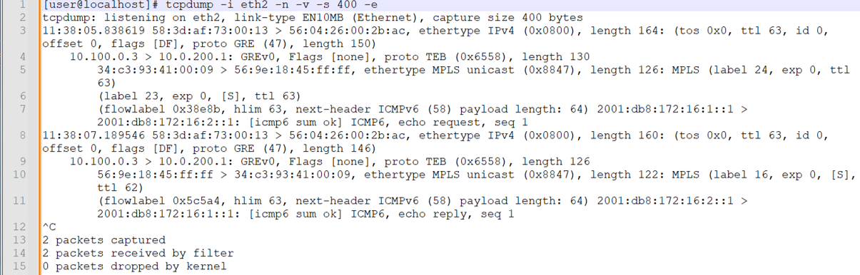
Note that both request and response traffic is shown. Given that this port mirror occurs on a P-router, OSPF packets between the CE routers are not mirrored as they are not sent over the provider core. Things to note in this capture include:
-
At line 3 the outer Ethernet frame is decoded. The source and destination MAC addresses now reflect the R4/PE2 and Analyzer devices, respectively.
-
At line 4 the inner IP packet is decoded. The frame indicates GRE encapsulation, and the source and destination IPs confirm this traffic is mirrored over the fti0.1 GRE tunnel configured at the R3/P1 router. The GRE encapsulation shows the TEB protocol, indicating that a Layer 2 Ethernet frame is encapsulated.
-
Line 5 begins the decode of the inner Ethernet frame and its MPLS payload. The source MAC address is assigned to the et-0/0/1 interface on the R2/PE1 router. The destination MAC is associated with the et-0/0/0 interface on the R3/P1 router.
The inner Ethernet frame identifies a payload of MPLS. This is in keeping with Layer 2 port mirroring performed at a P router with filter terms matching on MPLS labels.
Note that in the CE1 to CE2 direction, the mirrored traffic shows two MPLS labels. The RSVP transport label is 24 (this can change due to LSP re-signaling), and the inner VRF label set to 23, which is the VRF label associated with the CE1 routing instance at the R2/PE1 router.
Note:At the time of this capture the MPLS transport label used by PE1 to reach PE2 had changed. We updated the filter definition at R3/P1 to reflect the current RSVP transport label value of 24 for the captures in this section.
-
Line 7 decodes the IPv6 payload of the MPLS frame. This is the IPv6 packet sent by CE1 to the CE2. The IPv6 packet identifies its payload as ICMP6 and shows this is an echo request.
-
Line 8 begins the decode of the reply traffic from CE2. In the CE2 to CE1 direction only a single label is present in the mirror traffic. This is the VRF label that remains after the R3/PE1 router performs penultimate hop popping (PHP) before sending the traffic to the R2/PE1 router. The traffic mirrored at egress in the P1 to PE2 direction.
The captures at both analyzer devices confirm that remote port mirroring is working as expected.
-
-
We conclude with a GUI decode of the same CE to CE test traffic as captured on the Analyzer 2 device. Note again the presence of MPLS labels reflecting a port mirror operation on a MPLS-based PE router.
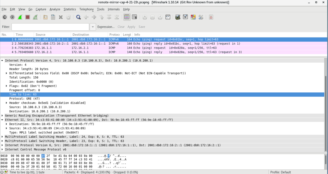 The capture
shows both IPv4 and IPv6 test traffic being mirrored. This capture reflects traffic that
is mirrored by the P router. As a result MPLS encapsulation is present.
The capture
shows both IPv4 and IPv6 test traffic being mirrored. This capture reflects traffic that
is mirrored by the P router. As a result MPLS encapsulation is present.
Appendix: Set Commands on All Routers
To quickly configure this example, copy the following commands, paste them into a text file, remove any line breaks, change any details necessary to match your network configuration, and then copy and paste the commands into the CLI at the [edit] hierarchy level.
R1 (CE1)
del interfaces et-0/0/0
set interfaces et-0/0/0 unit 0 family inet address 10.0.12.1/24
set interfaces et-0/0/0 unit 0 family inet6 address 2001:db8:10:0:12::1/64
set interfaces lo0 unit 0 family inet address 172.16.1.1/32
set interfaces lo0 unit 0 family inet6 address 2001:db8:172:16:1::1/128
set routing-options router-id 172.16.1.1
set protocols ospf area 0.0.0.0 interface all
set protocols ospf area 0.0.0.0 interface fxp0.0 disable
set protocols ospf3 area 0.0.0.0 interface all
set protocols ospf3 area 0.0.0.0 interface fxp0.0 disable
R2 (PE1) DUT1
set interfaces et-0/0/0 unit 0 filter input ce1-ce2
set interfaces et-0/0/0 unit 0 filter output ce2-ce1
set interfaces et-0/0/0 unit 0 family inet address 10.0.12.2/24
set interfaces et-0/0/0 unit 0 family inet6 address 2001:db8:10:0:12::2/64
set interfaces et-0/0/1 unit 0 family inet address 10.0.23.1/24
set interfaces et-0/0/1 unit 0 family inet6 address 2001:db8:10:0:23::1/64
set interfaces et-0/0/1 unit 0 family mpls
set interfaces fti0 unit 1 description "GRE tunnel for remote port mirror"
set interfaces fti0 unit 1 tunnel encapsulation gre source address 10.100.0.1
set interfaces fti0 unit 1 tunnel encapsulation gre destination address 10.0.100.1
set interfaces fti0 unit 1 family ccc
set interfaces lo0 unit 0 family inet address 192.168.0.2/32
set interfaces lo0 unit 0 family inet6 address 2001:db8:192:168:0::2/128
set forwarding-options port-mirroring instance pe-mirror input rate 1
set forwarding-options port-mirroring instance pe-mirror input run-length 1
set forwarding-options port-mirroring instance pe-mirror family any output interface fti0.1
set policy-options policy-statement ospf-export term 1 from protocol bgp
set policy-options policy-statement ospf-export term 1 then accept
set firewall family any filter ce1-ce2 term mirror-ce1-ce2 then count ce1-ce2-mirror
set firewall family any filter ce1-ce2 term mirror-ce1-ce2 then port-mirror-instance pe-mirror
set firewall family any filter ce1-ce2 term mirror-ce1-ce2 then accept
set firewall family any filter ce2-ce1 term mirror-ce2-ce1 then count ce2-ce1-mirror
set firewall family any filter ce2-ce1 term mirror-ce2-ce1 then port-mirror-instance pe-mirror
set firewall family any filter ce2-ce1 term mirror-ce2-ce1 then accept
set routing-instances ce1 instance-type vrf
set routing-instances ce1 protocols ospf area 0.0.0.0 interface all
set routing-instances ce1 protocols ospf export ospf-export
set routing-instances ce1 protocols ospf3 area 0.0.0.0 interface all
set routing-instances ce1 protocols ospf3 export ospf-export
set routing-instances ce1 interface et-0/0/0.0
set routing-instances ce1 route-distinguisher 65001:1
set routing-instances ce1 vrf-target target:65001:100
set routing-instances ce1 vrf-table-label
set routing-options router-id 192.168.0.2
set routing-options autonomous-system 65001
set protocols bgp group ibgp type internal
set protocols bgp group ibgp local-address 192.168.0.2
set protocols bgp group ibgp family inet unicast
set protocols bgp group ibgp family inet-vpn unicast
set protocols bgp group ibgp family inet6-vpn unicast
set protocols bgp group ibgp neighbor 192.168.0.4
set protocols mpls label-switched-path pe2 to 192.168.0.4
set protocols mpls label-switched-path pe2 no-cspf
set protocols mpls interface all
set protocols mpls interface fxp0.0 disable
set protocols ospf area 0.0.0.0 interface all
set protocols ospf area 0.0.0.0 interface fxp0.0 disable
set protocols ospf3 area 0.0.0.0 interface all
set protocols ospf3 area 0.0.0.0 interface fxp0.0 disable
set protocols ospf3 area 0.0.0.0 interface et-0/0/2.0 passive
set protocols rsvp interface all
set protocols rsvp interface fxp0 disable
R3 (P Router) DUT 2
set interfaces et-0/0/0 description "R3-R2 P-PE"
set interfaces et-0/0/0 unit 0 filter input ce1-ce2
set interfaces et-0/0/0 unit 0 filter output ce2-ce1
set interfaces et-0/0/0 unit 0 family inet address 10.0.23.2/24
set interfaces et-0/0/0 unit 0 family inet6 address 2001:db8:10:0:23::2/64
set interfaces et-0/0/0 unit 0 family mpls
set interfaces et-0/0/1 unit 0 family inet address 10.0.34.1/24
set interfaces et-0/0/1 unit 0 family inet6 address 2001:db8:10:0:34::1/64
set interfaces et-0/0/1 unit 0 family mpls
set interfaces et-0/0/2 unit 0 family inet address 10.0.100.2/24
set interfaces fti0 unit 1 tunnel encapsulation gre source address 10.100.0.3
set interfaces fti0 unit 1 tunnel encapsulation gre destination address 10.0.200.1
set interfaces fti0 unit 1 family ccc
set interfaces lo0 unit 0 family inet address 192.168.0.3/32
set interfaces lo0 unit 0 family inet6 address 2001:db8:192:168:0::3/128
set forwarding-options port-mirroring instance p-router-mirror input rate 1
set forwarding-options port-mirroring instance p-router-mirror input run-length 0
set forwarding-options port-mirroring instance p-router-mirror family any output interface fti0.1
set firewall family any filter ce1-ce2 term ce1-ce2-mirror from mpls-label 22
set firewall family any filter ce1-ce2 term ce1-ce2-mirror then count ce1-ce2-traffic
set firewall family any filter ce1-ce2 term ce1-ce2-mirror then port-mirror-instance p-router-mirror
set firewall family any filter ce1-ce2 term else then accept
set firewall family any filter ce2-ce1 term ce2-ce1-mirror from mpls-label 16
set firewall family any filter ce2-ce1 term ce2-ce1-mirror then count ce2-ce1-traffic
set firewall family any filter ce2-ce1 term ce2-ce1-mirror then port-mirror-instance p-router-mirror
set firewall family any filter ce2-ce1 term else then accept
set routing-options router-id 192.168.0.3
set protocols mpls interface all
set protocols mpls interface fxp0.0 disable
set protocols mpls interface et-0/0/2.0 disable
set protocols ospf area 0.0.0.0 interface all
set protocols ospf area 0.0.0.0 interface fxp0.0 disable
set protocols ospf area 0.0.0.0 interface et-0/0/2.0 passive
set protocols ospf3 area 0.0.0.0 interface all
set protocols ospf3 area 0.0.0.0 interface fxp0.0 disable
set protocols ospf3 area 0.0.0.0 interface et-0/0/2.0 passive
set protocols rsvp interface all
set protocols rsvp interface fxp0 disable
R4 (PE2)
set interfaces et-0/0/0 unit 0 family inet address 10.0.34.2/24
set interfaces et-0/0/0 unit 0 family inet6 address 2001:db8:10:0:34::2/64
set interfaces et-0/0/0 unit 0 family mpls
set interfaces et-0/0/1 unit 0 family inet address 10.0.45.1/24
set interfaces et-0/0/1 unit 0 family inet6 address 2001:db8:10:0:45::1/64
set interfaces et-0/0/2 unit 0 family inet address 10.0.200.2/24
set interfaces lo0 unit 0 family inet address 192.168.0.4/32
set interfaces lo0 unit 0 family inet6 address 2001:db8:192:168:0::4/128
set policy-options policy-statement ospf-export term 1 from protocol bgp
set policy-options policy-statement ospf-export term 1 then accept
set routing-instances ce2 instance-type vrf
set routing-instances ce2 protocols ospf area 0.0.0.0 interface all
set routing-instances ce2 protocols ospf export ospf-export
set routing-instances ce2 protocols ospf3 area 0.0.0.0 interface all
set routing-instances ce2 protocols ospf3 export ospf-export
set routing-instances ce2 interface et-0/0/1.0
set routing-instances ce2 route-distinguisher 65001:2
set routing-instances ce2 vrf-target target:65001:100
set routing-options router-id 192.168.0.4
set routing-options autonomous-system 65001
set protocols bgp group ibgp type internal
set protocols bgp group ibgp local-address 192.168.0.4
set protocols bgp group ibgp family inet unicast
set protocols bgp group ibgp family inet-vpn unicast
set protocols bgp group ibgp family inet6-vpn unicast
set protocols bgp group ibgp neighbor 192.168.0.2
set protocols mpls label-switched-path pe1 to 192.168.0.2
set protocols mpls label-switched-path pe1 no-cspf
set protocols mpls ipv6-tunneling
set protocols mpls interface all
set protocols mpls interface fxp0.0 disable
set protocols ospf area 0.0.0.0 interface all
set protocols ospf area 0.0.0.0 interface fxp0.0 disable
set protocols ospf area 0.0.0.0 interface et-0/0/2.0 passive
set protocols ospf3 area 0.0.0.0 interface all
set protocols ospf3 area 0.0.0.0 interface fxp0.0 disable
set protocols ospf3 area 0.0.0.0 interface et-0/0/2.0 passive
set protocols rsvp interface all
R5 (CE2)
set interfaces et-0/0/0 unit 0 family inet address 10.0.45.2/24
set interfaces et-0/0/0 unit 0 family inet6 address 2001:db8:10:0:45::2/64
set interfaces lo0 unit 0 family inet address 172.16.2.1/32
set interfaces lo0 unit 0 family inet6 address 2001:db8:172:16:2::1/128
set routing-options router-id 172.16.2.1
set protocols ospf area 0.0.0.0 interface all
set protocols ospf area 0.0.0.0 interface fxp0.0 disable
set protocols ospf3 area 0.0.0.0 interface all
set protocols ospf3 area 0.0.0.0 interface fxp0.0 disable
Caveats and Limitations
This section lists the caveats and limitations for remote port mirroring on PTX platforms.
-
If the output portion of the port mirroring instance configuration has to be changed, the existing output configuration should be deleted first and the change committed, before the new configuration is added.
-
A total of 15 mirror instances are supported. There is no commit error if the number of remote port mirror instances exceeds 15.
-
A given mirrored packet can be sent to only one remote analyzer.
-
The maximum packet length can be configured as multiple of 128 bytes. The exported packet will be 22 bytes less than the configured value.
-
Multiple output interfaces are not supported in a given mirroring instance. There is no commit error if multiple output interfaces are configured.
-
The sampling process is not GRES supported. There will be drops of mirrored traffic in the event of a GRES event or restart of the
mirrordprocess. -
Tunnel traffic that terminates on the local router cannot be mirrored in the egress direction.
-
You cannot use port mirroring with a filter that evokes a policer action in the egress direction.
-
Statistics related to mirrored packets must be verified through firewall counters or FTI interface statistics.