Example: Configuring Local Port Mirroring on PTX Routers
This example shows you how to configure and verify local port mirroring on PTX platforms running Junos Evolved. The PTX platforms include PTX10001-36MR, LC1201 and LC1202 in PTX10004, PTX10008 and PTX10016 chassis
Before You Begin
| Hardware and Software requirements | Junos OS Evolved Release 22.2R1.12-EVO or later. PTX10001-36MR See Feature Explorer for a complete listing of supported platforms and Junos OS versions. |
|
Estimated reading time |
Fifteen minutes. |
|
Estimated configuration time |
Thirty minutes |
|
Business impact |
Use this configuration example to configure local port mirroring feature. Port mirror is a critical tool for debugging and security related tasks. Mirror traffic can be analyzed offline by a variety of tools to either see protocol interactions or for anomaly detection. |
|
Know more |
To better understand Port Mirroring, see Port Mirroring and Analyzers |
|
Learn more |
Learning Portal |
Functional Overview
Table 1 provides a quick summary of the protocols and technologies deployed in this example.
|
Routing and Signaling protocols |
|
|
OSPF and OSPF3 |
All routers run OSPF and OSPF3 as the IGP. All routers belong to area 0 (also called the backbone area). The OSPF/OSPF3 routing domains provide internal reachability to all networks and interfaces in the topology. In this example the CE and PE/P devices are part of the same IGP routing domain. As a result, tunnels are not needed between the PE devices to transport CE traffic over the core. In addition, because this is a local mirror use case GRE encapsulation is not needed when sending mirrored traffic to the monitoring station. |
|
Routing Protocols |
|
|
IPv4 and IPv6 |
All devices are configured to support routing of both IPv4 and IPv6. |
|
Analyzer (monitoring station) |
|
|
Centos and Wireshark |
The analyzer runs Centos 7.x with a GUI version of Wireshark. |
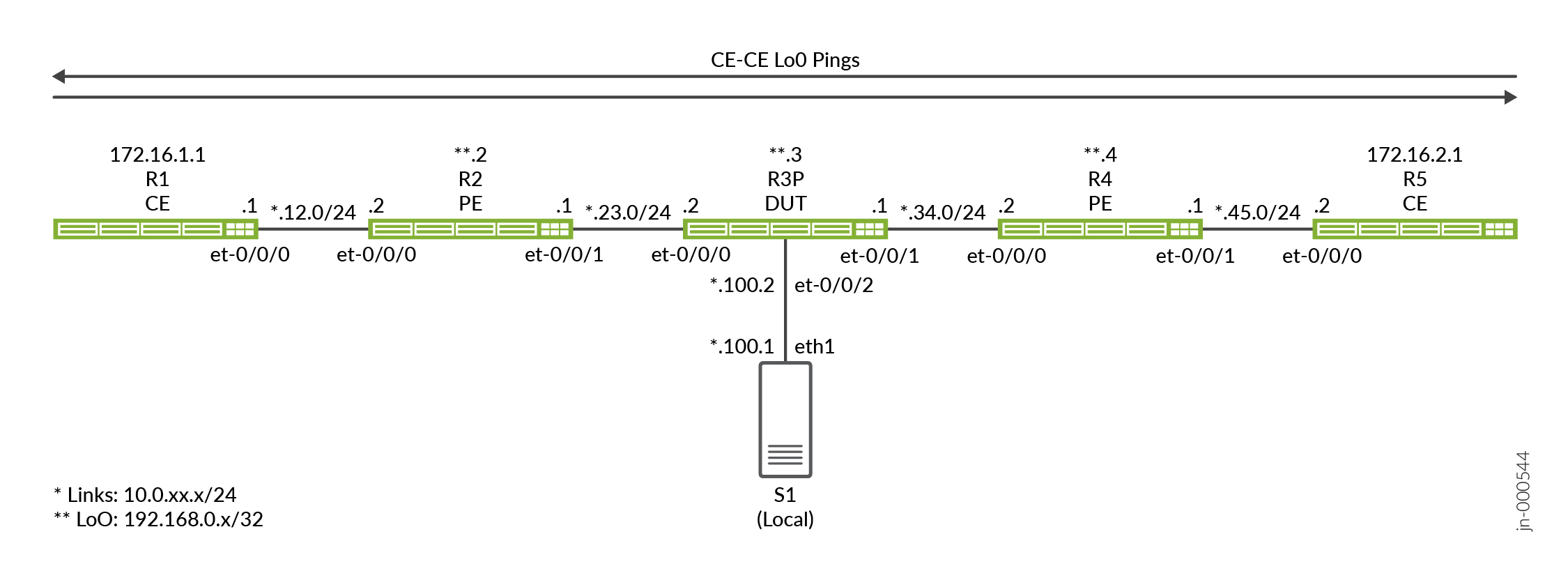
Topology Overview
In this example, the R3 device functions as the Device Under Test (DUT) as this is where port mirroring is configured. The device uses firewall filters to match the IP addresses associated with the CE devices to trigger the port mirror action. A combination of ingress and egress filters are employed to mirror both request and response traffic flowing between the CE devices (R1 and R5) .
The firewall filters that evoke packet sampling are applied to one or more of the transit interfaces on the R3 device.
| Device Name |
Role |
Function |
| CE | Customer Edge (CE) device that sends test traffic to confirm sampling works properly. | These devices are designated as CE devices. In most cases a CE device is part of a VPN service. Here, we let the CE share the same OSPF Area 0 as the provider devices to provide main instance IP connectivity. |
| PE | Provider Edge (PE) device that attaches to the CE. | Devices at the edge of a provider network. Our PEs run only OSPF. BGP and VPNs are not deployed. |
| P | A Provider (P) core router. | We opt to demonstrate port mirroring at a P router. You can configure port mirroring on any of the provider devices as needed. |
| Analyzer | The analyzer device received the mirror traffic for storage and analysis. | The specifics of the analyzer are outside the scope of this document. There are a number of open source and commercial options available. Our analyzer happens to be running Centos 7.x with a Gnome desktop supporting a GUIO version of Wireshark. |
Topology Illustrations
R3 Configuration Steps
For information about navigating the CLI, see Using the CLI Editor in Configuration Mode
For complete configuration on all devices see: Appendix 2: Set Commands on All Devices
This section highlights the main configuration tasks needed to configure the DUT, which is the P device (R3) in this example. Excluding the specifics used for sampling, all devices have a similar baseline configuration that supports main instance IPv6 and IPv4 connectivity.
-
Configure the IPv4 and IPv6 routing baseline. This includes numbering the loopback and core facing interfaces for both IPv4 and IPv6. You also define the OSPF and OSPFv3 routing protocol to provide reachability between all network interfaces.
A passive IGP instance is provisioned for the interface attached to the analyzer. This provides reachability for diagnostic purposes without having hello packets generated on the interface. An OSPF adjacency is not expected or needed to the analyzer device
[edit]
set interfaces et-0/0/0 unit 0 family inet address 10.0.23.2/24
set interfaces et-0/0/0 unit 0 family inet6 address 2001:db8:10:0:23::2/64
set interfaces et-0/0/1 unit 0 family inet address 10.0.34.1/24
set interfaces et-0/0/1 unit 0 family inet6 address 2001:db8:10:0:34::1/64
set interfaces et-0/0/2 unit 0 family inet address 10.0.100.2/24
set interfaces et-0/0/2 unit 0 family inet6 address 2001:db8:10:0:100::2/64
set interfaces lo0 unit 0 family inet address 192.168.0.3/32
set interfaces lo0 unit 0 family inet6 address 2001:db8:192:168:0::3/128

set routing-options router-id 192.168.0.3
set protocols ospf area 0.0.0.0 interface all
set protocols ospf area 0.0.0.0 interface fxp0.0 disable
set protocols ospf area 0 interface et-0/0/2.0 passive

set protocols ospf3 area 0.0.0.0 interface all
set protocols ospf3 area 0.0.0.0 interface fxp0.0 disable
set protocols ospf3 area 0 interface et-0/0/2.0 passive
Note: For the local mirror use case IP connectivity is only needed between the analyzer and the device doing the port mirroring. In this example we run a passive IGP on the interface attached to the analyzer. We also configure a default route on the analyzer to provide IP connectivity between it and the other devices. This provides the ability to test connectivity between the analyzer and all other devices. in the topology.This capability is most useful in a remote port mirror case where there is a need for Layer 3 reachability between the sampling device and the analyzer.
- Configure the sampling rate. We use a rate of 1 to select and sample all matching
packets. The default
run-lengthof 0 is left in place given all matching traffic is already sampled. You must also specify the egress interface and next hop address that the mirrored traffic is sent to. In this example of local port mirror, it should be noted that the interface and next hop addresses specified are directly attached to the DUT. As a result, no tunnels are needed or used when sending the mirrored traffic to the analyzer.[edit] set forwarding-options port-mirroring input rate 1 set forwarding-options port-mirroring family inet output interface et-0/0/2.0 next-hop 10.0.100.1 set forwarding-options port-mirroring family inet6 output interface et-0/0/2.0 next-hop 2001:db8:10:0:100::1
Note:This configuration assumes that the analyzer replies to ARP and ND request sent by the DUT for MAC address resolution. If this is not the case, or if you wish that ARP traffic is not part of your packet captures, you should configure a static ARP entry. Be sure to specify the correct MAC address for the interface on the analyzer device that is attached to the DUT.
-
Define the firewall filter to match on and then mirror IPv4 packets. Note that the filter's action specifies a port mirror action. This action directs matching traffic to the port mirroring instances you configured previously. Two filters are defined, one each for the source and destination addresses of CE1 and CE2, respectively. The filters include a count function to assist in confirmation of proper operation.
Don't overlook the final
accept-allterm that overrides the defaultdeny-allaction of a Junos firewall filter![edit] set firewall filter mirror_ce1 term term1 from source-address 172.16.1.1/32 set firewall filter mirror_ce1 term term1 from destination-address 172.16.2.1/32 set firewall filter mirror_ce1 term term1 then count mirror_ce1 set firewall filter mirror_ce1 term term1 then port-mirror set firewall filter mirror_ce1 term term1 then accept set firewall filter mirror_ce1 term accept-all then accept set firewall filter mirror_ce2 term term1 from source-address 172.16.2.1/32 set firewall filter mirror_ce2 term term1 from destination-address 172.16.1.1/32 set firewall filter mirror_ce2 term term1 then count mirror_ce2 set firewall filter mirror_ce2 term term1 then port-mirror set firewall filter mirror_ce2 term term1 then accept set firewall filter mirror_ce2 term accept-all then accept
-
Define the firewall filter to match and mirror IPv6 packets.
[edit]
set firewall family inet6 filter ce1_v6 term 1 from source-address 2001:db8:172:16:1::1/128
set firewall family inet6 filter ce1_v6 term 1 from destination-address 2001:db8:172:16:2::1/128
set firewall family inet6 filter ce1_v6 term 1 then count ce1_v6
set firewall family inet6 filter ce1_v6 term 1 then port-mirror
set firewall family inet6 filter ce1_v6 term 1 then accept
set firewall family inet6 filter ce1_v6 term accept-all then accept
set firewall family inet6 filter ce2_v6 term 1 from source-address 2001:db8:172:16:2::1/128
set firewall family inet6 filter ce2_v6 term 1 from destination-address 2001:db8:172:16:1::1/128
set firewall family inet6 filter ce2_v6 term 1 then count ce2_v6
set firewall family inet6 filter ce2_v6 term 1 then port-mirror
set firewall family inet6 filter ce2_v6 term 1 then accept
set firewall family inet6 filter ce2_v6 term accept-all then accept
-
Apply the IPv4 and IPv6 filters to the desired interfaces. In our example, we apply both filters to the et-0/0/0 interface. Note the directionality of the filter application. For each CE traffic flow (IPv4 or IPv6), we apply one filter as ingress and the other as egress. This method of application is compatible with the way the filters are written given the address assignments and directionality of the traffic.
[edit]
set interfaces et-0/0/0 unit 0 family inet filter input mirror_ce1
set interfaces et-0/0/0 unit 0 family inet filter output mirror_ce2

set interfaces et-0/0/0 unit 0 family inet6 filter input ce1_v6
set interfaces et-0/0/0 unit 0 family inet6 filter output ce2_v6
Verification
-
Confirm OSPF and OSPF3 neighbors and routes to all loopback addresses.
user@r3-ptx> show ospf neighbor

Address          Interface              State           ID               Pri  Dead
10.0.23.1        et-0/0/0.0             Full            192.168.0.2      128    31
10.0.34.2        et-0/0/1.0             Full            192.168.0.4      128    38

user@r3-ptx> show ospf3 neighbor

ID               Interface              State     Pri   Dead
192.168.0.2      et-0/0/0.0             Full      128     30
  Neighbor-address fe80::c6ba:25ff:fe48:9
192.168.0.4      et-0/0/1.0             Full      128     32
  Neighbor-address fe80::6204:30ff:fe6e:ffff

regress@r3-ptx> show route protocol ospf | match /32
172.16.1.1/32      *[OSPF/10] 01:04:02, metric 2
172.16.2.1/32      *[OSPF/10] 6d 00:47:07, metric 2
192.168.0.2/32     *[OSPF/10] 01:04:02, metric 1
192.168.0.4/32     *[OSPF/10] 6d 00:47:12, metric 1
224.0.0.5/32       *[OSPF/10] 6d 00:48:28, metric 1
224.0.0.6/32       *[OSPF/10] 6d 00:48:28, metric 1

regress@r3-ptx> show route protocol ospf3 | match /128
2001:db8:172:16:1::1/128
2001:db8:172:16:2::1/128
2001:db8:192:168::2/128*[OSPF3/10] 01:04:09, metric 1
2001:db8:192:168::4/128*[OSPF3/10] 6d 00:47:15, metric 1
ff02::5/128        *[OSPF3/10] 6d 00:48:35, metric 1
ff02::6/128        *[OSPF3/10] 6d 00:48:35, metric 1
-
Confirm the port mirroring instance on R3. Verify that the port mirroring state is
upfor the mirroring interface. Be sure to confirm theupstate for both the IPv4 and IPv6 families. While here, it is a good idea to confirm IP connectivity between the DUT and the analyzer. In our setup, a default route is configured on the analyzer to permit ping testing from all points of the network. Technically, the analyzer only has to be reachable by the DUT (R3), as this is an example of local port mirroring.user@r3-ptx> show forwarding-options port-mirroring Instance Name: &global_instance Instance Id: 1 Input parameters: Rate : 1 Run-length : 0 Maximum-packet-length : 0 Output parameters: Family State Destination Next-hop inet up et-0/0/2.0 10.0.100.1 inet6 up et-0/0/2.0 2001:db8:10:0:100::1 -
Clear the firewall counters and interface statistics on R3. Next, generate IPv4 and IPv6 test traffic between the CE devices and display the firewall counters on R3. Verify the filters applied to R3 correctly reflect the test traffic.
user@r3-ptx> clear firewall all
user@r3-ptx> clear interfaces statistics all
user@r1-ptx> ping 172.16.2.1 source 172.16.1.1 count 10 rapid
PING 172.16.2.1 (172.16.2.1) from 172.16.1.1 : 56(84) bytes of data.
--- 172.16.2.1 ping statistics ---
10 packets transmitted, 10 received, 0% packet loss, time 711ms
rtt min/avg/max/mdev = 11.161/72.078/364.497/121.714 ms, ipg/ewma 78.945/100.962 ms

user@r1-ptx> ping 2001:db8:172:16:2::1 source 2001:db8:172:16:1::1 count 10 rapid
 ping 2001:db8:172:16:2::1 source 2001:db8:172:16:1::1 count 10 rapid
PING 2001:db8:172:16:2::1(2001:db8:172:16:2::1) from 2001:db8:172:16:1::1 : 56 data bytes

--- 2001:db8:172:16:2::1 ping statistics ---
10 packets transmitted, 10 received, 0% packet loss, time 2436ms
rtt min/avg/max/mdev = 11.363/247.188/518.314/226.132 ms, pipe 2, ipg/ewma 270.652/201.439 ms
-
Display the firewall counters on R3. Verify if the filters applied to R3 correctly reflect the test traffic you generated.
user@r3-ptx> show firewall
Filter: mirror_ce1
Counters:
Name                                                Bytes              Packets
mirror_ce1                                             840                   10

Filter: mirror_ce2
Counters:
Name                                                Bytes              Packets
mirror_ce2                                             840                   10

Filter: ce1_v6
Counters:
Name                                                Bytes              Packets
ce1_v6                                                1040                   10

Filter: ce2_v6
Counters:
Name                                                Bytes              Packets
ce2_v6                                                1040                   10
-
Display interface statistics for R3's et-0/0/2.0 interface that is attached to the analyzer. The goal is to confirm output traffic counters that correlate to the test traffic generated. With ten pings for both IPv4 and IPv6, and given that we mirror both request and replies, you can expect to see about 40 output packets.
user@r3-ptx> show interfaces et-0/0/2.0 detail Logical interface et-0/0/2.0 (Index 1017) (SNMP ifIndex 541) (Generation 704374637676) Flags: Up SNMP-Traps Encapsulation: ENET2 Traffic statistics: Input bytes : 0 Output bytes : 3760 Input packets: 0 Output packets: 40 Local statistics: Input bytes : 0 Output bytes : 0 Input packets: 0 Output packets: 0 Transit statistics: Input bytes : 0 0 bps Output bytes : 3760 0 bps Input packets: 0 0 pps Output packets: 40 0 pps -
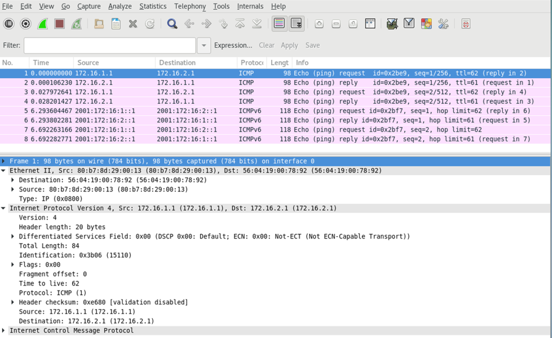
Run tcpdump or the analysis application of your choice on the monitoring station to confirm receipt and processing of the mirrored test traffic. To keep the size of the capture smaller, we generated new test traffic with only two ping requests for each IPv4 and IPv6. The capture and decode confirms that port mirroring of IPv4 and IPv6, based on a firewall filter matching, is working as expected. Note that both request and response traffic is shown.
Also, in the capture, note that only the Layer 3 traffic is mirrored. The Layer 2 encapsulation shown is generated by the DUT (R3) when forwarding the mirrored traffic to the analyzer. You can configure port mirroring for Layer 2 services like Ethernet switching or VXLAN when you need to preserve the original Layer 2 frame.
Appendix: Set Commands on All Devices
To quickly configure this example, copy the following commands, paste them into a text file, remove any line breaks, change any details necessary to match your network configuration, and then copy and paste the commands into the CLI at the [edit] hierarchy level.
R1 (CE)
set system host-name r1-ptx
set interfaces et-0/0/0 unit 0 family inet address 10.0.12.1/24
set interfaces et-0/0/0 unit 0 family inet6 address 2001:db8:10:0:12::1/64
set interfaces lo0 unit 0 family inet address 172.16.1.1/32
set interfaces lo0 unit 0 family inet6 address 2001:db8:172:16:1::1/128
set routing-options router-id 172.16.1.1
set protocols ospf area 0.0.0.0 interface all
set protocols ospf area 0.0.0.0 interface fxp0.0 disable
set protocols ospf3 area 0.0.0.0 interface all
set protocols ospf3 area 0.0.0.0 interface fxp0.0 disable
R2 (PE)
set system host-name r2-ptx
set interfaces et-0/0/0 unit 0 family inet address 10.0.12.2/24
set interfaces et-0/0/0 unit 0 family inet6 address 2001:db8:10:0:12::2/64
set interfaces et-0/0/1 unit 0 family inet address 10.0.23.1/24
set interfaces et-0/0/1 unit 0 family inet6 address 2001:db8:10:0:23::1/64
set interfaces et-0/0/2 unit 0 family inet tunnel-termination
set interfaces et-0/0/2 unit 0 family inet address 10.0.100.2/24
set interfaces lo0 unit 0 family inet address 192.168.0.2/32
set interfaces lo0 unit 0 family inet6 address 2001:db8:192:168:0::2/128
set routing-options router-id 192.168.0.2
set protocols ospf area 0.0.0.0 interface all
set protocols ospf area 0.0.0.0 interface fxp0.0 disable
set protocols ospf3 area 0.0.0.0 interface all
set protocols ospf3 area 0.0.0.0 interface fxp0.0 disable
R3 (DUT)
set system host-name r3-ptx
set interfaces et-0/0/0 unit 0 family inet filter input mirror_ce1
set interfaces et-0/0/0 unit 0 family inet filter output mirror_ce2
set interfaces et-0/0/0 unit 0 family inet address 10.0.23.2/24
set interfaces et-0/0/0 unit 0 family inet6 filter input ce1_v6
set interfaces et-0/0/0 unit 0 family inet6 filter output ce2_v6
set interfaces et-0/0/0 unit 0 family inet6 address 2001:db8:10:0:23::2/64
set interfaces et-0/0/1 unit 0 family inet address 10.0.34.1/24
set interfaces et-0/0/1 unit 0 family inet6 address 2001:db8:10:0:34::1/64
set interfaces et-0/0/2 unit 0 family inet address 10.0.100.2/24
set interfaces et-0/0/2 unit 0 family inet6 address 2001:db8:10:0:100::2/64
set interfaces lo0 unit 0 family inet address 192.168.0.3/32
set interfaces lo0 unit 0 family inet6 address 2001:db8:192:168:0::3/128
set forwarding-options port-mirroring input rate 1
set forwarding-options port-mirroring input run-length 0
set forwarding-options port-mirroring family inet output interface et-0/0/2.0 next-hop 10.0.100.1
set forwarding-options port-mirroring family inet6 output interface et-0/0/2.0 next-hop 2001:db8:10:0:100::1
set firewall family inet6 filter ce1_v6 term 1 from source-address 2001:db8:172:16:1::1/128
set firewall family inet6 filter ce1_v6 term 1 from destination-address 2001:db8:172:16:2::1/128
set firewall family inet6 filter ce1_v6 term 1 then count ce1_v6
set firewall family inet6 filter ce1_v6 term 1 then port-mirror
set firewall family inet6 filter ce1_v6 term 1 then accept
set firewall family inet6 filter ce1_v6 term accept-all then accept
set firewall family inet6 filter ce2_v6 term 1 from source-address 2001:db8:172:16:2::1/128
set firewall family inet6 filter ce2_v6 term 1 from destination-address 2001:db8:172:16:1::1/128
set firewall family inet6 filter ce2_v6 term 1 then count ce2_v6
set firewall family inet6 filter ce2_v6 term 1 then port-mirror
set firewall family inet6 filter ce2_v6 term 1 then accept
set firewall family inet6 filter ce2_v6 term accept-all then accept
set firewall filter mirror_ce1 term 1 from source-address 172.16.1.1/32
set firewall filter mirror_ce1 term 1 from destination-address 172.16.2.1/32
set firewall filter mirror_ce1 term 1 then count mirror_ce1
set firewall filter mirror_ce1 term 1 then port-mirror
set firewall filter mirror_ce1 term 1 then accept
set firewall filter mirror_ce1 term accept-all then accept
set firewall filter mirror_ce2 term term1 from source-address 172.16.2.1/32
set firewall filter mirror_ce2 term 1 from destination-address 172.16.1.1/32
set firewall filter mirror_ce2 term 1 then count mirror_ce2
set firewall filter mirror_ce2 term 1 then port-mirror
set firewall filter mirror_ce2 term 1 then accept
set firewall filter mirror_ce2 term accept-all  then accept
set routing-options router-id 192.168.0.3
set protocols ospf area 0.0.0.0 interface all
set protocols ospf area 0.0.0.0 interface fxp0.0 disable
set protocols ospf area 0.0.0.0 interface et-0/0/2.0 passive
set protocols ospf3 area 0.0.0.0 interface all
set protocols ospf3 area 0.0.0.0 interface fxp0.0 disable
set protocols ospf3 area 0.0.0.0 interface et-0/0/2.0 passive
R4 (PE)
set system host-name r4-ptx
set interfaces et-0/0/0 unit 0 family inet address 10.0.34.2/24
set interfaces et-0/0/0 unit 0 family inet6 address 2001:db8:10:0:34::2/64
set interfaces et-0/0/1 unit 0 family inet address 10.0.45.1/24
set interfaces et-0/0/1 unit 0 family inet6 address 2001:db8:10:0:45::1/64
set interfaces et-0/0/2 unit 0 family inet address 10.0.200.2/24
set interfaces et-0/0/2 unit 0 family inet6 address 2001:db8:10:0:200::2/64
set interfaces lo0 unit 0 family inet address 192.168.0.4/32
set interfaces lo0 unit 0 family inet6 address 2001:db8:192:168:0::4/128
set routing-options router-id 192.168.0.4
set protocols ospf area 0.0.0.0 interface all
set protocols ospf area 0.0.0.0 interface fxp0.0 disable
set protocols ospf3 area 0.0.0.0 interface all
set protocols ospf3 area 0.0.0.0 interface fxp0.0 disable
R5 (CE)
set system host-name r5-ptx
set interfaces et-0/0/0 unit 0 family inet address 10.0.45.2/24
set interfaces et-0/0/0 unit 0 family inet6 address 2001:db8:10:0:45::2/64
set interfaces lo0 unit 0 family inet address 172.16.2.1/32
set interfaces lo0 unit 0 family inet6 address 2001:db8:172:16:2::1/128
set routing-options router-id 172.16.2.1
set protocols ospf area 0.0.0.0 interface all
set protocols ospf area 0.0.0.0 interface fxp0.0 disable
set protocols ospf3 area 0.0.0.0 interface all
set protocols ospf3 area 0.0.0.0 interface fxp0.0 disable