ON THIS PAGE
Example: Configuring a Stateless Firewall Filter to Protect a Logical System Against ICMP Floods
This example shows how to configure a stateless firewall filter that protects against ICMP denial-of-service attacks on a logical system.
Requirements
In this example, no special configuration beyond device initialization is required.
Overview
This example shows a stateless firewall filter called protect-RE that polices ICMP packets. The icmp-policer limits the traffic rate of the ICMP packets to 1,000,000 bps and the burst size to 15,000 bytes. Packets that exceed the traffic rate are discarded.
The policer is incorporated into the action of a filter term called icmp-term.
In this example, a ping is sent from a directly connected physical router to the interface
configured on the logical system. The logical system accepts the ICMP packets if they are
received at a rate of up to 1 Mbps (bandwidth-limit). The logical system drops all ICMP packets
when this rate is exceeded. The burst-size-limit statement accepts traffic bursts
up to 15 Kbps. If bursts exceed this limit, all packets are dropped. When the flow rate subsides,
ICMP packets are again accepted.
Topology
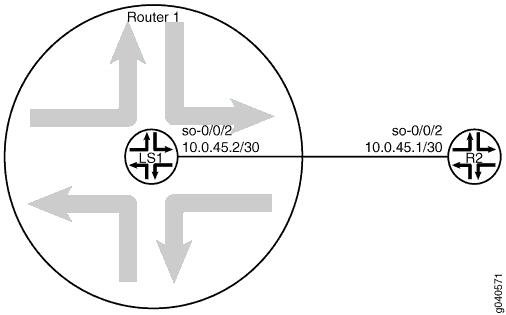
Figure 1 shows the topology used in this example.

Configuration
CLI Quick Configuration
To quickly configure this example, copy the following commands, paste
them into a text file, remove any line breaks, change any details necessary to match your
network configuration, and then copy and paste the commands into the CLI at the [edit] hierarchy level.
set logical-systems LS1 interfaces ge-0/0/2 unit 0 family inet policer input icmp-policer
set logical-systems LS1 interfaces ge-0/0/2 unit 0 family inet address 10.0.45.2/30
set logical-systems LS1 firewall family inet filter protect-RE term icmp-term from protocol icmp
set logical-systems LS1 firewall family inet filter protect-RE term icmp-term then policer icmp-policer
set logical-systems LS1 firewall family inet filter protect-RE term icmp-term then accept
set logical-systems LS1 firewall policer icmp-policer if-exceeding bandwidth-limit 1m
set logical-systems LS1 firewall policer icmp-policer if-exceeding burst-size-limit 15k
set logical-systems LS1 firewall policer icmp-policer then discard
Procedure
Step-by-Step Procedure
The following example requires you to navigate various levels in the configuration hierarchy. For information about navigating the CLI, see Use the CLI Editor in Configuration Mode in the Junos OS CLI User Guide.
To configure an ICMP firewall filter on a logical system:
Configure the interface on the logical system.
[edit]
user@host# set logical-systems LS1 interfaces ge-0/0/2 unit 0 family inet address 10.0.45.2/30
Explicitly enable ICMP packets to be received on the interface.
[edit]
user@host# set logical-systems LS1 firewall family inet filter protect-RE term icmp-term from protocol icmp
user@host# set logical-systems LS1 firewall family inet filter protect-RE term icmp-term then accept
Create the policer.
[edit]
user@host# set logical-systems LS1 firewall policer icmp-policer if-exceeding bandwidth-limit 1m
user@host# set logical-systems LS1 firewall policer icmp-policer if-exceeding burst-size-limit 15k
user@host# set logical-systems LS1 firewall policer icmp-policer then discard
Apply the policer to a filter term.
[edit]
user@host# set logical-systems LS1 firewall family inet filter protect-RE term icmp-term then policer icmp-policer
Apply the policer to the logical system interface.
[edit]
user@host# set logical-systems LS1 interfaces ge-0/0/2 unit 0 family inet policer input icmp-policer
If you are done configuring the device, commit the configuration.
[edit]
user@host# commit
Results
Confirm your configuration by issuing the show logical-systems LS1 command.
user@host# show logical-systems LS1
interfaces {
    ge-0/0/2 {
        unit 0 {
            family inet {
                policer {
                    input icmp-policer;
                }
                address 10.0.45.2/30;
            }
        }
    }
}
firewall {
    family inet {
        filter protect-RE {
            term icmp-term {
                from {
                    protocol icmp;
                }
                then {
                    policer icmp-policer;
                    accept;
                }
            }
        }
    }
    policer icmp-policer {
        if-exceeding {
            bandwidth-limit 1m;
            burst-size-limit 15k;
        }
        then discard;
    }
}
Verification
Confirm that the configuration is working properly.
Verifying That Ping Works Unless the Limits Are Exceeded
Purpose
Make sure that the logical system interface is protected against ICMP-based DoS attacks.
Action
Log in to a system that has connectivity to the logical system and run the ping command.
user@R2> ping 10.0.45.2
PING 10.0.45.2 (10.0.45.2): 56 data bytes
64 bytes from 10.0.45.2: icmp_seq=0 ttl=64 time=1.316 ms
64 bytes from 10.0.45.2: icmp_seq=1 ttl=64 time=1.277 ms
64 bytes from 10.0.45.2: icmp_seq=2 ttl=64 time=1.269 ms
user@R2> ping 10.0.45.2 size 20000
PING 10.0.45.2 (10.0.45.2): 20000 data bytes
^C
--- 10.0.45.2 ping statistics ---
4 packets transmitted, 0 packets received, 100% packet loss
Meaning
When you send a normal ping, the packet is accepted. When you send a ping packet that exceeds the filter limit, the packet is discarded.
