ON THIS PAGE
Example: Configuring and Applying a Stateless Firewall Filter to Match Packets Received On an Interface Group
Firewall filters are essential for securing a network and simplifying network management. In Junos OS, you can configure stateless firewall filters to control the transit of data packets through the system and to manipulate packets as necessary. Applying a stateless firewall filter to match packets received on an interface group helps to filter packets transiting through each interface in the interface group. This example shows how to configure a standard stateless firewall filter to match packets tagged for a particular interface group.
Requirements
This example uses the following hardware and software components:
-
Any two Juniper Networks routers or switches that are physically or logically connected to each other through interfaces belonging to a routing instance
Overview
You can apply a stateless firewall filter to match packets received on an interface group.
In this example, you configure two router or switch interfaces to belong to the
interface group. You also configure a stateless firewall filter with three terms. In
term term1, the filter matches packets that have been tagged as
received on that interface group
and
contain an ICMP protocol
tag. The filter
counts, logs, and rejects packets that match the conditions. In term
term2, the filter matches packets that contain the ICMP
protocol tag. The filter counts, logs, and accepts all packets that match the
condition. In term term3, the filter counts all the transit
packets.
Note that all the interfaces in the interface group must belong to a single routing instance.
When you apply a firewall filter to a loopback interface, the interface filters all the packets destined to the Routing Engine.
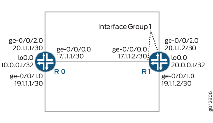
CLI Quick Configuration shows the configuration for all of the devices in Figure 1. The section Step-by-Step Procedure describes the steps on Device R1.
Configuration
- CLI Quick Configuration
- Configure and Apply the Stateless Firewall Filter on an Interface Group
- Results
CLI Quick Configuration
To quickly configure this example, copy the
following commands, paste them into a text file, remove any line breaks,
change any details necessary to match your network configuration,
copy and paste the commands into the CLI at the [edit] hierarchy
level, and then enter commit from configuration mode.
Device R0
set interfaces ge-0/0/0 unit 0 family inet address 172.16.17.1/30
set interfaces ge-0/0/1 unit 0 family inet address 172.16.19.1/30
set interfaces ge-0/0/2 unit 0 family inet address 20.1.1.1/30
set interfaces lo0 unit 0 family inet address 10.0.0.1/32
Device R1
set firewall family inet filter filter_if_group term term1 from interface-group 1
set firewall family inet filter filter_if_group term term1 from protocol icmp
set firewall family inet filter filter_if_group term term1 then count if_group_counter1
set firewall family inet filter filter_if_group term term1 then log
set firewall family inet filter filter_if_group term term1 then reject
set firewall family inet filter filter_if_group term term2 from protocol icmp
set firewall family inet filter filter_if_group term term2 then count if_group_counter2
set firewall family inet filter filter_if_group term term2 then log
set firewall family inet filter filter_if_group term term2 then accept
set firewall family inet filter filter_if_group term term3 then count default
set interfaces ge-0/0/0 unit 0 family inet filter group 1
set interfaces ge-0/0/0 unit 0 family inet address 172.16.17.2/30
set interfaces ge-0/0/1 unit 0 family inet address 172.16.19.2/30
set interfaces ge-0/0/2 unit 0 family inet filter group 1
set interfaces ge-0/0/2 unit 0 family inet address 20.1.1.2/30
set interfaces lo0 unit 0 family inet address 20.0.0.1/32
set forwarding-options family inet filter input filter_if_group
Configure and Apply the Stateless Firewall Filter on an Interface Group
Step-by-Step Procedure
The following example requires you to navigate various levels in the configuration hierarchy. For information about navigating the CLI, see Use the CLI Editor in Configuration Mode in the CLI User Guide.
To configure the stateless firewall filter filter_if_group on an interface group:
Create the stateless firewall filter
filter_if_group.[edit firewall] user@R1# edit family inet filter filter_if_group
Configure the interfaces and assign two interfaces to interface group
1.[edit interfaces] user@R1# set ge-0/0/0 unit 0 family inet filter group 1 user@R1# set ge-0/0/0 unit 0 family inet address 172.16.17.2/30 user@R1# set ge 0/0/1 unit 0 family inet address 172.16.19.2/30 user@R1# set ge-0/0/2 unit 0 family inet filter group 1 user@R1# set ge-0/0/2 unit 0 family inet address 20.1.1.2/30 user@R1# set lo0 unit 0 family inet address 20.0.0.1/32
Configure term
term1to match packets received on interface group1and with the ICMP protocol.[edit firewall] user@R1# set family inet filter filter_if_group term term1 from interface-group 1 user@R1# set family inet filter filter_if_group term term1 from protocol icmp
Configure term
term1to count, log, and reject all the matching packets.[edit firewall] user@R1# set family inet filter filter_if_group term term1 then count if_group_counter1 user@R1# set family inet filter filter_if_group term term1 then log user@R1# set family inet filter filter_if_group term term1 then reject
Configure term
term2to match packets with the ICMP protocol.[edit firewall] user@R1# set family inet filter filter_if_group term term2 from protocol icmp
Configure term
term2to count, log, and accept all the matching packets.[edit firewall] user@R1# set family inet filter filter_if_group term term2 then count if_group_counter2 user@R1# set family inet filter filter_if_group term term2 then log user@R1# set family inet filter filter_if_group term term2 then accept
Configure term
term3to count all the transit packets.[edit firewall] user@R1# set family inet filter filter_if_group term term3 then count default
Apply the firewall filter to the routing instance.
[edit]
user@R1# set forwarding-options family inet filter input filter_if_group
If you are done configuring the device, commit your candidate configuration.
[edit]
user@host# commit
Results
From configuration mode, confirm your configuration
by issuing the show interfaces, show firewall, and show forwarding-options commands. If the output
does not display the intended configuration, repeat the instructions
in this example to correct the configuration.
[edit]
user@R1# show interfaces
ge-0/0/0 {
    unit 0 {
        family inet {
            filter {
                group 1;
            }
            address 172.16.17.2/30;
        }
    }
}
ge-0/0/1 {
    unit 0 {
        family inet {
            address 172.16.19.2/30;
        }
    }
}
ge-0/0/2 {
    unit 0 {
        family inet {
            filter {
                group 1;
            }
            address 20.1.1.2/30;
        }
    }
}
lo0 {
    unit 0 {
        family inet {
            address 20.0.0.1/32;
        }
    }
}
[edit]
user@R1# show firewall
family inet {
    filter filter_if_group {
        term term1 {
            from {
                interface-group 1;
                protocol icmp;
            }
            then {
                count if_group_counter1;
                log;
                reject;
            }
        }
        term term2 {
            from {
                protocol icmp;
            }
            then {
                count if_group_counter2;
                log;
                accept;
            }
        }
        term term3 {
            then count default;
        }
    }
}
[edit]
user@R1# show forwarding-options
family inet {
    filter {
        input filter_if_group;
    }
}
Verification
Confirm that the configuration is working properly.
Verifying the Configuration of the Interfaces
Purpose
Verify that the interfaces are properly configured.
Action
To display the state of the interfaces, use the show interfaces terse operational mode command.
Device R0
user@R0> show interfaces terse
Interface               Admin Link Proto    Local                 Remote
ge-0/0/0                up    up
ge-0/0/0.0              up    up   inet     172.16.17.1/30
                                   multiservice
ge-0/0/1                up    up
ge-0/0/1.0              up    up   inet     172.16.19.1/30
                                   multiservice
ge-0/0/2                up    up
ge-0/0/2.0              up    up   inet     20.1.1.1/30
                                   multiservice
lo0                     up    up
lo0.0                   up    up   inet     10.0.0.1            --> 0/0
Device R1
user@R1> show interfaces terse
Interface               Admin Link Proto    Local                 Remote
ge-0/0/0                up    up
ge-0/0/0.0              up    up   inet     172.16.17.2/30
                                   multiservice
...
ge-0/0/1                up    up
ge-0/0/1.0              up    up   inet     172.16.19.2/30
                                   multiservice
ge-0/0/2                up    up
ge-0/0/2.0              up    up   inet     20.1.1.2/30
                                   multiservice
...
Meaning
All the interfaces on Devices R0 and R1 are physically
connected and up. The interface group 1 on Device R1 consists
of two interfaces, namely ge-0/0/0.0 and ge-0/0/2.0.
Verifying Stateless Firewall Filter Configuration
Purpose
Verify that the firewall filter match conditions are configured properly.
Action
To display the firewall filter counters, enter the
show firewall filter filter_if_groupoperational mode command.user@R1> show firewall filter filter_if_group Filter: filter_if_group Counters: Name Bytes Packets default 192975 3396 if_group_counter1 2520 30 if_group_counter2 2604 41
To display the local log of packet headers for packets evaluated by the firewall filter, enter the
show firewall logoperational mode command.user@R1> show firewall log Log : Time Filter Action Interface Protocol Src Addr Dest Addr 22:27:33 pfe A lo0.0 ICMP 20.1.1.2 20.1.1.1 22:27:33 pfe R ge-0/0/2.0 ICMP 20.1.1.1 20.1.1.2 22:27:32 pfe A lo0.0 ICMP 20.1.1.2 20.1.1.1 22:27:32 pfe R ge-0/0/2.0 ICMP 20.1.1.1 20.1.1.2 22:27:31 pfe A lo0.0 ICMP 20.1.1.2 20.1.1.1 22:27:31 pfe R ge-0/0/2.0 ICMP 20.1.1.1 20.1.1.2 22:27:30 pfe A lo0.0 ICMP 20.1.1.2 20.1.1.1 22:27:30 pfe R ge-0/0/2.0 ICMP 20.1.1.1 20.1.1.2 22:27:29 pfe A lo0.0 ICMP 20.1.1.2 20.1.1.1 22:27:29 pfe A lo0.0 ICMP 20.1.1.2 20.1.1.1 22:27:29 pfe R ge-0/0/2.0 ICMP 20.1.1.1 20.1.1.2 22:27:21 pfe A ge-0/0/1.0 ICMP 172.16.19.1 172.16.19.2 22:27:20 pfe A ge-0/0/1.0 ICMP 172.16.19.1 172.16.19.2 22:27:19 pfe A ge-0/0/1.0 ICMP 172.16.19.1 172.16.19.2 22:27:18 pfe A ge-0/0/1.0 ICMP 172.16.19.1 172.16.19.2 22:27:04 pfe A lo0.0 ICMP 172.16.17.2 172.16.17.1 22:27:04 pfe R ge-0/0/0.0 ICMP 172.16.17.1 172.16.17.2 22:27:04 pfe A lo0.0 ICMP 172.16.17.2 172.16.17.1 22:27:04 pfe R ge-0/0/0.0 ICMP 172.16.17.1 172.16.17.2 22:27:02 pfe A lo0.0 ICMP 172.16.17.2 172.16.17.1 22:27:02 pfe R ge-0/0/0.0 ICMP 172.16.17.1 172.16.17.2 22:27:01 pfe A lo0.0 ICMP 172.16.17.2 172.16.17.1 22:27:01 pfe R ge-0/0/0.0 ICMP 172.16.17.1 172.16.17.2 22:27:00 pfe A lo0.0 ICMP 172.16.17.2 172.16.17.1 22:27:00 pfe R ge-0/0/0.0 ICMP 172.16.17.1 172.16.17.2 22:24:48 filter_if_group A fxp0.0 ICMP 10.92.16.2 10.92.26.176
To make sure that the firewall filters are active on interface group
1on Device R1, use theping <address>operational mode command on the CLI of Device R0.user@R0> ping 172.16.17.2 PING 172.16.17.2 (172.16.17.2): 56 data bytes 36 bytes from 172.16.17.2: Communication prohibited by filter Vr HL TOS Len ID Flg off TTL Pro cks Src Dst 4 5 00 0054 f46b 0 0000 40 01 6239 172.16.17.1 172.16.17.2 36 bytes from 172.16.17.2: Communication prohibited by filter Vr HL TOS Len ID Flg off TTL Pro cks Src Dst 4 5 00 0054 f479 0 0000 40 01 622b 172.16.17.1 172.16.17.2 36 bytes from 172.16.17.2: Communication prohibited by filter Vr HL TOS Len ID Flg off TTL Pro cks Src Dst 4 5 00 0054 f487 0 0000 40 01 621d 172.16.17.1 172.16.17.2
user@R0> ping 20.1.1.2
PING 20.1.1.2 (20.1.1.2): 56 data bytes
36 bytes from 20.1.1.2: Communication prohibited by filter
Vr HL TOS  Len   ID Flg  off TTL Pro  cks      Src      Dst
 4  5  00 0054 f5bd   0 0000  40  01 5ae7 20.1.1.1  20.1.1.2

36 bytes from 20.1.1.2: Communication prohibited by filter
Vr HL TOS  Len   ID Flg  off TTL Pro  cks      Src      Dst
 4  5  00 0054 f5cd   0 0000  40  01 5ad7 20.1.1.1  20.1.1.2

36 bytes from 20.1.1.2: Communication prohibited by filter
Vr HL TOS  Len   ID Flg  off TTL Pro  cks      Src      Dst
 4  5  00 0054 f5d9   0 0000  40  01 5acb 20.1.1.1  20.1.1.2

36 bytes from 20.1.1.2: Communication prohibited by filter
Vr HL TOS  Len   ID Flg  off TTL Pro  cks      Src      Dst
 4  5  00 0054 f5f6   0 0000  40  01 5aae 20.1.1.1  20.1.1.2
To make sure that the firewall filter is not applied on an interface that is not in interface group
1, use theping <address>operational mode command on the CLI of Device R0.user@R0> ping 172.16.19.2 PING 172.16.19.2 (172.16.19.2): 56 data bytes 64 bytes from 172.16.19.2: icmp_seq=0 ttl=64 time=8.689 ms 64 bytes from 172.16.19.2: icmp_seq=1 ttl=64 time=4.076 ms 64 bytes from 172.16.19.2: icmp_seq=2 ttl=64 time=8.501 ms 64 bytes from 172.16.19.2: icmp_seq=3 ttl=64 time=3.954 ms ...
Meaning
The stateless firewall filter is applied to all interfaces
in interface group 1. The term term1 match condition
in the stateless firewall filter counts, logs, and rejects packets
that are received on or sent from the interfaces in interface group 1 and with a source ICMP protocol. The term term2 match condition matches packets tagged with the ICMP protocol and
counts, logs, and accepts those packets. The term term3 match condition counts all the transit packets.