ON THIS PAGE
Example: Advertising Multiple Paths in BGP
In this example, BGP routers are configured to advertise multiple paths instead of advertising only the active path. Advertising multiple paths in BGP is specified in RFC 7911, Advertisement of Multiple Paths in BGP.
Requirements
This example uses the following hardware and software components:
Eight BGP-enabled devices.
Five of the BGP-enabled devices do not necessarily need to be routers. For example, they can be EX Series Ethernet Switches.
Three of the BGP-enabled devices are configured to send multiple paths or receive multiple paths (or both send and receive multiple paths). These three BGP-enabled devices must be M Series Multiservice Edge Routers, MX Series 5G Universal Routing Platforms, or T Series Core Routers.
The three routers must be running Junos OS Release 11.4 or later.
Overview
The following statements are used for configuring multiple paths to a destination:
[edit protocols bgp group group-name family family]
add-path {
    receive;
    send {
        include-backup-path include-backup-path;
        multipath;
        path-count path-count;
        path-selection-mode {
            (all-paths | equal-cost-paths);
        }
        prefix-policy [ policy-names ... ];
    }
}
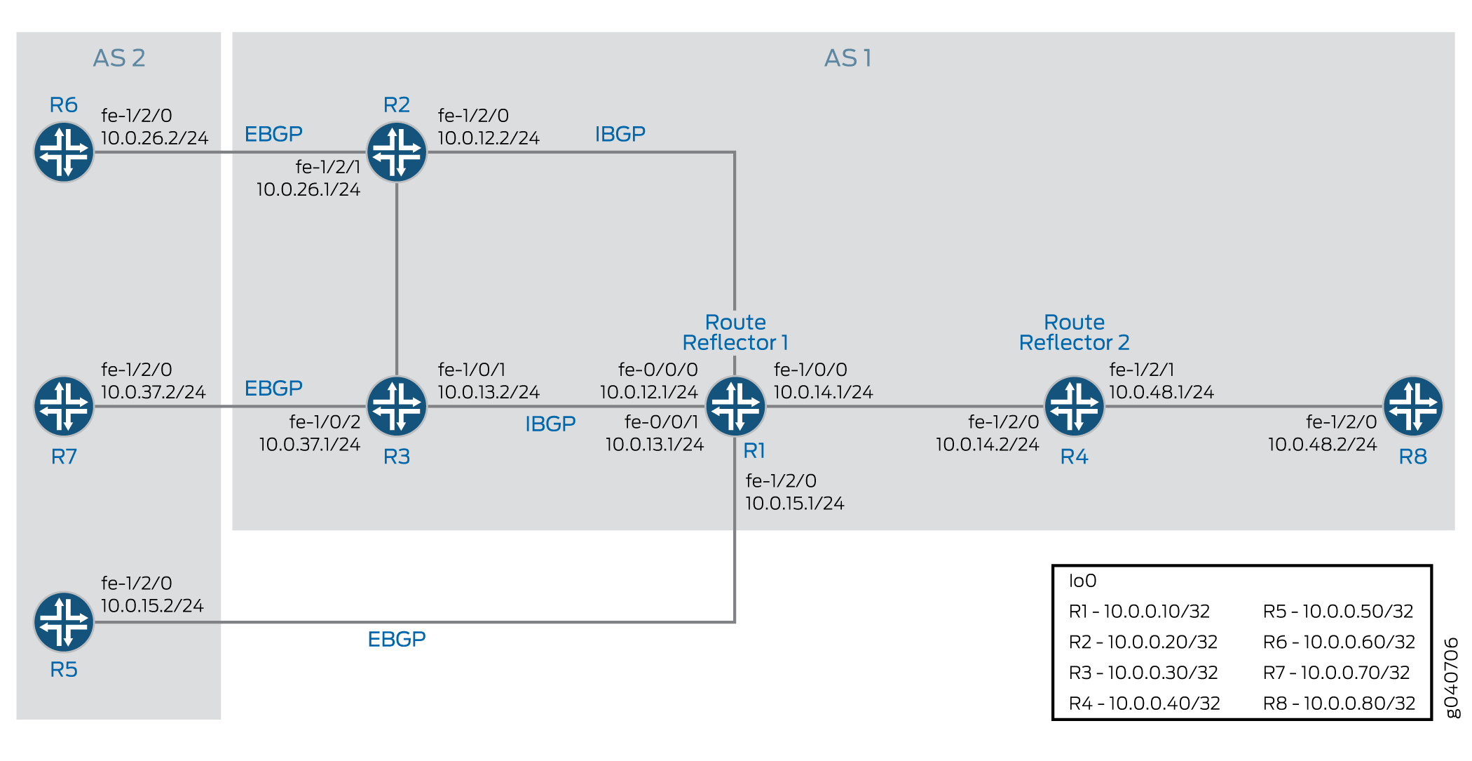
In this example, Router R5, Router R6, and Router R7 redistribute static routes into BGP. Router R1 and Router R4 are route reflectors. Router R2 and Router R3 are clients to Route Reflector R1. Router R8 is a client to Route Reflector R4.
Route reflection is optional when multiple-path advertisement is enabled in BGP.
With the add-path send path-count 6 configuration,
Router R1 is configured to send up to six paths (per destination)
to Router R4.
With the add-path receive configuration, Router R4
is configured to receive multiple paths from Router R1.
With the add-path send path-count 6 configuration,
Router R4 is configured to send up to six paths to Router R8.
With the add-path receive configuration, Router R8
is configured to receive multiple paths from Router R4.
The add-path send prefix-policy allow_199 policy
configuration (along with the corresponding route filter) limits Router
R4 to sending multiple paths for only the 172.16.199.1/32 route.
Topology Diagram
Figure 1 shows the topology used in this example.
Configuration
- CLI Quick Configuration
- Configuring Router R1
- Configuring Router R2
- Configuring Router R3
- Configuring Router R4
- Configuring Router R5
- Configuring Router R6
- Configuring Router R7
- Configuring Router R8
- Results
CLI Quick Configuration
To quickly configure this example, copy the
following commands, paste them into a text file, remove any line breaks,
change any details necessary to match your network configuration,
and then copy and paste the commands into the CLI at the [edit] hierarchy level.
Router R1
set interfaces fe-0/0/0 unit 12 family inet address 10.0.12.1/24
set interfaces fe-0/0/1 unit 13 family inet address 10.0.13.1/24
set interfaces fe-1/0/0 unit 14 family inet address 10.0.14.1/24
set interfaces fe-1/2/0 unit 15 family inet address 10.0.15.1/24
set interfaces lo0 unit 10 family inet address 10.0.0.10/32
set protocols bgp group rr type internal
set protocols bgp group rr local-address 10.0.0.10
set protocols bgp group rr cluster 10.0.0.10
set protocols bgp group rr neighbor 10.0.0.20
set protocols bgp group rr neighbor 10.0.0.30
set protocols bgp group e1 type external
set protocols bgp group e1 neighbor 10.0.15.2 local-address 10.0.15.1
set protocols bgp group e1 neighbor 10.0.15.2 peer-as 2
set protocols bgp group rr_rr type internal
set protocols bgp group rr_rr local-address 10.0.0.10
set protocols bgp group rr_rr neighbor 10.0.0.40 family inet unicast add-path send path-count 6
set protocols ospf area 0.0.0.0 interface lo0.10 passive
set protocols ospf area 0.0.0.0 interface fe-0/0/0.12
set protocols ospf area 0.0.0.0 interface fe-0/0/1.13
set protocols ospf area 0.0.0.0 interface fe-1/0/0.14
set protocols ospf area 0.0.0.0 interface fe-1/2/0.15
set routing-options router-id 10.0.0.10
set routing-options autonomous-system 1
Router R2
set interfaces fe-1/2/0 unit 21 family inet address 10.0.12.2/24
set interfaces fe-1/2/1 unit 26 family inet address 10.0.26.1/24
set interfaces lo0 unit 20 family inet address 10.0.0.20/32
set protocols bgp group rr type internal
set protocols bgp group rr local-address 10.0.0.20
set protocols bgp group rr neighbor 10.0.0.10 export set_nh_self
set protocols bgp group e1 type external
set protocols bgp group e1 neighbor 10.0.26.2 peer-as 2
set protocols ospf area 0.0.0.0 interface lo0.20 passive
set protocols ospf area 0.0.0.0 interface fe-1/2/0.21
set protocols ospf area 0.0.0.0 interface fe-1/2/1.28
set policy-options policy-statement set_nh_self then next-hop self
set routing-options autonomous-system 1
Router R3
set interfaces fe-1/0/1 unit 31 family inet address 10.0.13.2/24
set interfaces fe-1/0/2 unit 37 family inet address 10.0.37.1/24
set interfaces lo0 unit 30 family inet address 10.0.0.30/32
set protocols bgp group rr type internal
set protocols bgp group rr local-address 10.0.0.30
set protocols bgp group rr neighbor 10.0.0.10 export set_nh_self
set protocols bgp group e1 type external
set protocols bgp group e1 neighbor 10.0.37.2 peer-as 2
set protocols ospf area 0.0.0.0 interface lo0.30 passive
set protocols ospf area 0.0.0.0 interface fe-1/0/1.31
set protocols ospf area 0.0.0.0 interface fe-1/0/2.37
set policy-options policy-statement set_nh_self then next-hop self
set routing-options autonomous-system 1
Router R4
set interfaces fe-1/2/0 unit 41 family inet address 10.0.14.2/24
set interfaces fe-1/2/1 unit 48 family inet address 10.0.48.1/24
set interfaces lo0 unit 40 family inet address 10.0.0.40/32
set protocols bgp group rr type internal
set protocols bgp group rr local-address 10.0.0.40
set protocols bgp group rr family inet unicast add-path receive
set protocols bgp group rr neighbor 10.0.0.10
set protocols bgp group rr_client type internal
set protocols bgp group rr_client local-address 10.0.0.40
set protocols bgp group rr_client cluster 10.0.0.40
set protocols bgp group rr_client neighbor 10.0.0.80 family inet unicast add-path send path-count 6
set protocols bgp group rr_client neighbor 10.0.0.80 family inet unicast add-path send prefix-policy allow_199
set protocols ospf area 0.0.0.0 interface fe-1/2/0.41
set protocols ospf area 0.0.0.0 interface lo0.40 passive
set protocols ospf area 0.0.0.0 interface fe-1/2/1.48
set policy-options policy-statement allow_199 from route-filter 172.16.199.1/32 exact
set policy-options policy-statement allow_199 term match_199 from prefix-list match_199
set policy-options policy-statement allow_199 then add-path send-count 20
set policy-options policy-statement allow_199 then accept
set routing-options autonomous-system 1
Router R5
set interfaces fe-1/2/0 unit 51 family inet address 10.0.15.2/24
set interfaces lo0 unit 50 family inet address 10.0.0.50/32
set protocols bgp group e1 type external
set protocols bgp group e1 neighbor 10.0.15.1 export s2b
set protocols bgp group e1 neighbor 10.0.15.1 peer-as 1
set policy-options policy-statement s2b from protocol static
set policy-options policy-statement s2b from protocol direct
set policy-options policy-statement s2b then as-path-expand 2
set policy-options policy-statement s2b then accept
set routing-options autonomous-system 2
set routing-options static route 172.16.199.1/32 reject
set routing-options static route 172.16.198.1/32 reject
Router R6
set interfaces fe-1/2/0 unit 62 family inet address 10.0.26.2/24
set interfaces lo0 unit 60 family inet address 10.0.0.60/32
set protocols bgp group e1 type external
set protocols bgp group e1 neighbor 10.0.26.1 export s2b
set protocols bgp group e1 neighbor 10.0.26.1 peer-as 1
set policy-options policy-statement s2b from protocol static
set policy-options policy-statement s2b from protocol direct
set policy-options policy-statement s2b then accept
set routing-options autonomous-system 2
set routing-options static route 172.16.199.1/32 reject
set routing-options static route 172.16.198.1/32 reject
Router R7
set interfaces fe-1/2/0 unit 73 family inet address 10.0.37.2/24
set interfaces lo0 unit 70 family inet address 10.0.0.70/32
set protocols bgp group e1 type external
set protocols bgp group e1 neighbor 10.0.37.1 export s2b
set protocols bgp group e1 neighbor 10.0.37.1 peer-as 1
set policy-options policy-statement s2b from protocol static
set policy-options policy-statement s2b from protocol direct
set policy-options policy-statement s2b then accept
set routing-options autonomous-system 2
set routing-options static route 172.16.199.1/32 reject
Router R8
set interfaces fe-1/2/0 unit 84 family inet address 10.0.48.2/24
set interfaces lo0 unit 80 family inet address 10.0.0.80/32
set protocols bgp group rr type internal
set protocols bgp group rr local-address 10.0.0.80
set protocols bgp group rr neighbor 10.0.0.40 family inet unicast add-path receive
set protocols ospf area 0.0.0.0 interface lo0.80 passive
set protocols ospf area 0.0.0.0 interface fe-1/2/0.84
set routing-options autonomous-system 1
Configuring Router R1
Step-by-Step Procedure
The following example requires you to navigate various levels in the configuration hierarchy. For information about navigating the CLI, see Using the CLI Editor in Configuration Mode in the Junos OS CLI User Guide.
To configure Router R1:
Configure the interfaces to Router R2, Router R3, Router R4, and Router R5, and configure the loopback (lo0) interface.
[edit interfaces]
user@R1# set fe-0/0/0 unit 12 family inet address 10.0.12.1/24
user@R1# set fe-0/0/1 unit 13 family inet address 10.0.13.1/24
user@R1# set fe-1/0/0 unit 14 family inet address 10.0.14.1/24
user@R1# set fe-1/2/0 unit 15 family inet address 10.0.15.1/24
user@R1#set lo0 unit 10 family inet address 10.0.0.10/32
Configure BGP on the interfaces, and configure IBGP route reflection.
[edit protocols bgp]
user@R1# set group rr type internal
user@R1# set group rr local-address 10.0.0.10
user@R1# set group rr cluster 10.0.0.10
user@R1# set group rr neighbor 10.0.0.20
user@R1# set group rr neighbor 10.0.0.30
user@R1# set group rr_rr type internal
user@R1# set group rr_rr local-address 10.0.0.10
user@R1# set group e1 type external
user@R1# set group e1 neighbor 10.0.15.2 local-address 10.0.15.1
user@R1# set group e1 neighbor 10.0.15.2 peer-as 2
Configure Router R1 to send up to six paths to its neighbor, Router R4.
The destination of the paths can be any destination that Router R1 can reach through multiple paths.
[edit protocols bgp]
user@R1# set group rr_rr neighbor 10.0.0.40 family inet unicast add-path send path-count 6
Configure OSPF on the interfaces.
[edit protocols ospf]
user@R1# set area 0.0.0.0 interface lo0.10 passive
user@R1# set area 0.0.0.0 interface fe-0/0/0.12
user@R1# set area 0.0.0.0 interface fe-0/0/1.13
user@R1# set area 0.0.0.0 interface fe-1/0/0.14
user@R1# set area 0.0.0.0 interface fe-1/2/0.15
Configure the router ID and the autonomous system number.
[edit routing-options]
user@R1# set router-id 10.0.0.10
user@R1# set autonomous-system 1
If you are done configuring the device, commit the configuration.
user@R1# commit
Results
From configuration mode, confirm your configuration
by entering the show interfaces, show protocols, show policy-options, and show routing-options commands. If the output does not display the intended configuration,
repeat the instructions in this example to correct the configuration.
user@R1# show interfaces
fe-0/0/0 {
    unit 12 {
        family inet {
            address 10.0.12.1/24;
        }
    }
}
fe-0/0/1 {
    unit 13 {
        family inet {
            address 10.0.13.1/24;
        }
    }
}
fe-1/0/0 {
    unit 14 {
        family inet {
            address 10.0.14.1/24;
        }
    }
}
fe-1/2/0 {
    unit 15 {
        family inet {
            address 10.0.15.1/24;
        }
    }
}
lo0 {
    unit 10 {
        family inet {
            address 10.0.0.10/32;
        }
    }
}
user@R1# show protocols
bgp {
    group rr {
        type internal;
        local-address 10.0.0.10;
        cluster 10.0.0.10;
        neighbor 10.0.0.20;
        neighbor 10.0.0.30;
    }
    group e1 {
        type external;
        neighbor 10.0.15.2 {
            local-address 10.0.15.1;
            peer-as 2;
        }
    }
    group rr_rr {
        type internal;
        local-address 10.0.0.10;
        neighbor 10.0.0.40 {
            family inet {
                unicast {
                    add-path {
                        send {
                            path-count 6;
                        }
                    }
                }
            }
        }
    }
}
ospf {
    area 0.0.0.0 {
        interface lo0.10 {
            passive;
        }
        interface fe-0/0/0.12;
        interface fe-0/0/1.13;
        interface fe-1/0/0.14;
        interface fe-1/2/0.15;
    }
}
user@R1# show routing-options
router-id 10.0.0.10;
 autonomous-system 1;
Configuring Router R2
Step-by-Step Procedure
To configure Router R2:
Configure the loopback (lo0) interface and the interfaces to Router R6 and Router R1.
[edit interfaces]
user@R2# set fe-1/2/0 unit 21 family inet address 10.0.12.2/24
user@R2# set fe-1/2/1 unit 26 family inet address 10.0.26.1/24
user@R2# set lo0 unit 20 family inet address 10.0.0.20/32
Configure BGP and OSPF on Router R2’s interfaces.
[edit protocols]
user@R2# set bgp group rr type internal
user@R2# set bgp group rr local-address 10.0.0.20
user@R2# set bgp group e1 type external
user@R2# set bgp group e1 neighbor 10.0.26.2 peer-as 2
user@R2# set ospf area 0.0.0.0 interface lo0.20 passive
user@R2# set ospf area 0.0.0.0 interface fe-1/2/0.21
user@R2# set ospf area 0.0.0.0 interface fe-1/2/1.28
For routes sent from Router R2 to Router R1, advertise Router R2 as the next hop, because Router R1 does not have a route to Router R6’s address on the 10.0.26.0/24 network.
[edit]
user@R2# set policy-options policy-statement set_nh_self then next-hop self
user@R2# set protocols bgp group rr neighbor 10.0.0.10 export set_nh_self
Configure the autonomous system number.
[edit]
user@R2# set routing-options autonomous-system 1
If you are done configuring the device, commit the configuration.
user@R2# commit
Results
From configuration mode, confirm your configuration
by entering the show interfaces, show protocols, show policy-options,and show routing-options commands. If the output does not display the intended configuration,
repeat the instructions in this example to correct the configuration.
user@R2# show interfaces
fe-1/2/0 {
    unit 21 {
        family inet {
            address 10.0.12.2/24;
        }
    }
}
fe-1/2/1 {
    unit 26 {
        family inet {
            address 10.0.26.1/24;
        }
    }
}
lo0 {
    unit 20 {
        family inet {
            address 10.0.0.20/32;
        }
    }
}
user@R2# show protocols
bgp {
    group rr {
        type internal;
        local-address 10.0.0.20;
        neighbor 10.0.0.10 {
            export set_nh_self;
        }
    }
    group e1 {
        type external;
        neighbor 10.0.26.2 {
            peer-as 2;
        }
    }
}
ospf {
    area 0.0.0.0 {
        interface lo0.20 {
            passive;
        }
        interface fe-1/2/0.21;
        interface fe-1/2/1.28;
    }
}
user@R2# show policy-options
policy-statement set_nh_self {
    then {
        next-hop self;
    }
}
user@R2# show routing-options
 autonomous-system 1;
Configuring Router R3
Step-by-Step Procedure
To configure Router R3:
Configure the loopback (lo0) interface and the interfaces to Router R7 and Router R1.
[edit interfaces]
user@R3# set fe-1/0/1 unit 31 family inet address 10.0.13.2/24
user@R3# set fe-1/0/2 unit 37 family inet address 10.0.37.1/24
user@R3# set lo0 unit 30 family inet address 10.0.0.30/32
Configure BGP and OSPF on Router R3’s interfaces.
[edit protocols]
user@R3# set bgp group rr type internal
user@R3# set bgp group rr local-address 10.0.0.30
user@R3# set bgp group e1 type external
user@R3# set bgp group e1 neighbor 10.0.37.2 peer-as 2
user@R3# set ospf area 0.0.0.0 interface lo0.30 passive
user@R3# set ospf area 0.0.0.0 interface fe-1/0/1.31
user@R3# set ospf area 0.0.0.0 interface fe-1/0/2.37
For routes sent from Router R3 to Router R1, advertise Router R3 as the next hop, because Router R1 does not have a route to Router R7’s address on the 10.0.37.0/24 network.
[edit]
user@R3# set policy-options policy-statement set_nh_self then next-hop self
user@R3# set protocols bgp group rr neighbor 10.0.0.10 export set_nh_self
Configure the autonomous system number.
[edit]
user@R3# set routing-options autonomous-system 1
If you are done configuring the device, commit the configuration.
user@R3# commit
Results
From configuration mode, confirm your configuration
by entering the show interfaces, show protocols, show policy-options, and show routing-options commands. If the output does not display the intended configuration,
repeat the instructions in this example to correct the configuration.
user@R3# show interfaces
fe-1/0/1 {
    unit 31 {
        family inet {
            address 10.0.13.2/24;
        }
    }
}
fe-1/0/2 {
    unit 37 {
        family inet {
            address 10.0.37.1/24;
        }
    }
}
lo0 {
    unit 30 {
        family inet {
            address 10.0.0.30/32;
        }
    }
}
user@R3# show protocols
bgp {
    group rr {
        type internal;
        local-address 10.0.0.30;
        neighbor 10.0.0.10 {
            export set_nh_self;
        }
    }
    group e1 {
        type external;
        neighbor 10.0.37.2 {
            peer-as 2;
        }
    }
}
ospf {
    area 0.0.0.0 {
        interface lo0.30 {
            passive;
        }
        interface fe-1/0/1.31;
        interface fe-1/0/2.37;
    }
}
user@R3# show policy-options
policy-statement set_nh_self {
    then {
        next-hop self;
    }
}
user@R3# show routing-options
 autonomous-system 1;
Configuring Router R4
Step-by-Step Procedure
To configure Router R4:
Configure the interfaces to Router R1 and Router R8, and configure the loopback (lo0) interface.
[edit interfaces]
user@R4# set fe-1/2/0 unit 41 family inet address 10.0.14.2/24
user@R4# set fe-1/2/1 unit 48 family inet address 10.0.48.1/24
user@R4# set lo0 unit 40 family inet address 10.0.0.40/32
Configure BGP on the interfaces, and configure IBGP route reflection.
[edit protocols bgp]
user@R4# set group rr type internal
user@R4# set group rr local-address 10.0.0.40
user@R4# set group rr neighbor 10.0.0.10
user@R4# set group rr_client type internal
user@R4# set group rr_client local-address 10.0.0.40
user@R4# set group rr_client cluster 10.0.0.40
Configure Router R4 to send up to six paths to its neighbor, Router R8.
The destination of the paths can be any destination that Router R4 can reach through multiple paths.
[edit protocols bgp]
user@R4# set group rr_client neighbor 10.0.0.80 family inet unicast add-path send path-count 6
Configure Router R4 to receive multiple paths from its neighbor, Router R1.
The destination of the paths can be any destination that Router R1 can reach through multiple paths.
[edit protocols bgp group rr family inet unicast]
user@R4# set add-path receive
Configure OSPF on the interfaces.
[edit protocols ospf area 0.0.0.0]
user@R4# set interface fe-1/2/0.41
user@R4# set interface lo0.40 passive
user@R4# set interface fe-1/2/1.48
Configure a policy that allows Router R4 to send Router R8 multiple paths to the 172.16.199.1/32 route.
Router R4 receives multiple paths for the 172.16.198.1/32 route and the 172.16.199.1/32 route. However, because of this policy, Router R4 only sends multiple paths for the 172.16.199.1/32 route.
[edit protocols bgp group rr_client neighbor 10.0.0.80 family inet unicast]
user@R4# set add-path send prefix-policy allow_199
[edit policy-options policy-statement allow_199]
user@R4# set from route-filter 172.16.199.1/32 exact
user@R4# set then accept
Router R4 can also be configured to send up-to 20 BGP
add-pathroutes for a subset of add-path advertised prefixes.[edit policy-options policy-statement allow_199] user@R4# set term match_199 from prefix-list match_199 user@R4# set then add-path send-count 20
Configure the autonomous system number.
[edit routing-options]
user@R4# set autonomous-system 1
If you are done configuring the device, commit the configuration.
user@R4# commit
Results
From configuration mode, confirm your configuration
by entering the show interfaces, show protocols, show policy-options, and show routing-options commands. If the output does not display the intended configuration,
repeat the instructions in this example to correct the configuration.
user@R4# show interfaces
fe-1/2/0 {
    unit 41 {
        family inet {
            address 10.0.14.2/24;
        }
    }
}
fe-1/2/1 {
    unit 48 {
        family inet {
            address 10.0.48.1/24;
        }
    }
}
lo0 {
    unit 40 {
        family inet {
            address 10.0.0.40/32;
        }
    }
}
user@R4# show protocols
bgp {
    group rr {
        type internal;
        local-address 10.0.0.40;
        family inet {
            unicast {
                add-path {
                    receive;
                }
            }
        }
        neighbor 10.0.0.10;
    }
    group rr_client {
        type internal;
        local-address 10.0.0.40;
        cluster 10.0.0.40;
        neighbor 10.0.0.80 {
            family inet {
                unicast {
                    add-path {
                        send {
                            path-count 6;
                            prefix-policy allow_199;
                        }
                    }
                }
            }
        }
    }
}
ospf {
    area 0.0.0.0 {
        interface lo0.40 {
            passive;
        }
        interface fe-1/2/0.41;
        interface fe-1/2/1.48;
    }
}
user@R4# show policy-options
policy-statement allow_199 {
    from {
        route-filter 172.16.199.1/32 exact;
    }
    from term match_199 {
        prefix-list match_199;
    }
        then add-path send-count 20;
    then accept;
}
user@R4# show routing-options
 autonomous-system 1;
Configuring Router R5
Step-by-Step Procedure
To configure Router R5:
Configure the loopback (lo0) interface and the interface to Router R1.
[edit interfaces]
user@R5# set fe-1/2/0 unit 51 family inet address 10.0.15.2/24
user@R5# set lo0 unit 50 family inet address 10.0.0.50/32
Configure BGP on Router R5’s interface.
[edit protocols bgp group e1]
user@R5# set type external
user@R5# set neighbor 10.0.15.1 peer-as 1
Create static routes for redistribution into BGP.
[edit routing-options]
user@R5# set static route 172.16.199.1/32 reject
user@R5# set static route 172.16.198.1/32 reject
Redistribute static and direct routes into BGP.
[edit protocols bgp group e1 neighbor 10.0.15.1]
user@R5# set export s2b
[edit policy-options policy-statement s2b]
user@R5# set from protocol static
user@R5# set from protocol direct
user@R5# set then as-path-expand 2
user@R5# set then accept
Configure the autonomous system number.
[edit routing-options]
user@R5# set autonomous-system 2
If you are done configuring the device, commit the configuration.
user@R5# commit
Results
From configuration mode, confirm your configuration
by entering the show interfaces, show protocols, show policy-options, and show routing-options commands. If the output does not display the intended configuration,
repeat the instructions in this example to correct the configuration.
user@R5# show interfaces
fe-1/2/0 {
    unit 51 {

        family inet {
            address 10.0.15.2/24;
        }
    }
}
lo0 {
    unit 50 {
        family inet {
            address 10.0.0.50/32;
        }
    }
}
user@R5# show protocols
bgp {
    group e1 {
        type external;
        neighbor 10.0.15.1 {
            export s2b;
            peer-as 1;
        }
    }
}
user@R5# show policy-options
policy-statement s2b {
    from protocol [ static direct ];
    then {
        as-path-expand 2;
        accept;
    }
}
user@R5# show routing-options
static {
    route 172.16.198.1/32 reject;
    route 172.16.199.1/32 reject;
}
 autonomous-system 2;
Configuring Router R6
Step-by-Step Procedure
To configure Router R6:
Configure the loopback (lo0) interface and the interface to Router R2.
[edit interfaces]
user@R6# set fe-1/2/0 unit 62 family inet address 10.0.26.2/24
user@R6# set lo0 unit 60 family inet address 10.0.0.60/32
Configure BGP on Router R6’s interface.
[edit protocols]
user@R6# set bgp group e1 type external
user@R6# set bgp group e1 neighbor 10.0.26.1 peer-as 1
Create static routes for redistribution into BGP.
[edit]
user@R6# set routing-options static route 172.16.199.1/32 reject
user@R6# set routing-options static route 172.16.198.1/32 reject
Redistribute static and direct routes from Router R6’s routing table into BGP.
[edit protocols bgp group e1 neighbor 10.0.26.1]
user@R6# set export s2b
[edit policy-options policy-statement s2b]
user@R6# set from protocol static
user@R6# set from protocol direct
user@R6# set then accept
Configure the autonomous system number.
[edit routing-options]
user@R6# set autonomous-system 2
If you are done configuring the device, commit the configuration.
user@R6# commit
Results
From configuration mode, confirm your configuration
by entering the show interfaces, show protocols, show policy-options, and show routing-options commands. If the output does not display the intended configuration,
repeat the instructions in this example to correct the configuration.
user@R6# show interfaces
fe-1/2/0 {
    unit 62 {

        family inet {
            address 10.0.26.2/24;
        }
    }
}
lo0 {
    unit 60 {
        family inet {
            address 10.0.0.60/32;
        }
    }
}
user@R6# show protocols
bgp {
    group e1 {
        type external;
        neighbor 10.0.26.1 {
            export s2b;
            peer-as 1;
        }
    }
}
user@R6# show policy-options
policy-statement s2b {
    from protocol [ static direct ];
    then accept;
}
user@R6# show routing-options
static {
    route 172.16.198.1/32 reject;
    route 172.16.199.1/32 reject;
}
 autonomous-system 2;
Configuring Router R7
Step-by-Step Procedure
To configure Router R7:
Configure the loopback (lo0) interface and the interface to Router R3.
[edit interfaces]
user@R7# set fe-1/2/0 unit 73 family inet address 10.0.37.2/24
user@R7# set lo0 unit 70 family inet address 10.0.0.70/32
Configure BGP on Router R7’s interface.
[edit protocols bgp group e1]
user@R7# set type external
user@R7# set neighbor 10.0.37.1 peer-as 1
Create a static route for redistribution into BGP.
[edit]
user@R7# set routing-options static route 172.16.199.1/32 reject
Redistribute static and direct routes from Router R7’s routing table into BGP.
[edit protocols bgp group e1 neighbor 10.0.37.1]
user@R7# set export s2b
[edit policy-options policy-statement s2b]
user@R7# set from protocol static
user@R7# set from protocol direct
user@R7# set then accept
Configure the autonomous system number.
[edit routing-options]
user@R7# set autonomous-system 2
If you are done configuring the device, commit the configuration.
user@R7# commit
Results
From configuration mode, confirm your configuration
by entering the show interfaces, show protocols, show policy-options, and show routing-options commands. If the output does not display the intended configuration,
repeat the instructions in this example to correct the configuration.
user@R7# show interfaces
fe-1/2/0 {
    unit 73 {

        family inet {
            address 10.0.37.2/24;
        }
    }
}
lo0 {
    unit 70 {
        family inet {
            address 10.0.0.70/32;
        }
    }
}
user@R7# show protocols
bgp {
    group e1 {
        type external;
        neighbor 10.0.37.1 {
            export s2b;
            peer-as 1;
        }
    }
}
user@R7# show policy-options
policy-statement s2b {
    from protocol [ static direct ];
    then accept;
}
user@R7# show routing-options
static {
    route 172.16.199.1/32 reject;
}
 autonomous-system 2;
Configuring Router R8
Step-by-Step Procedure
To configure Router R8:
Configure the loopback (lo0) interface and the interface to Router R4.
[edit interfaces]
user@R8# set fe-1/2/0 unit 84 family inet address 10.0.48.2/24
user@R8# set lo0 unit 80 family inet address 10.0.0.80/32
Configure BGP and OSPF on Router R8’s interface.
[edit protocols]
user@R8# set bgp group rr type internal
user@R8# set bgp group rr local-address 10.0.0.80
user@R8# set ospf area 0.0.0.0 interface lo0.80 passive
user@R8# set ospf area 0.0.0.0 interface fe-1/2/0.84
Configure Router R8 to receive multiple paths from its neighbor, Router R4.
The destination of the paths can be any destination that Router R4 can reach through multiple paths.
[edit protocols]
user@R8# set bgp group rr neighbor 10.0.0.40 family inet unicast add-path receive
Configure the autonomous system number.
[edit]
user@R8# set routing-options autonomous-system 1
If you are done configuring the device, commit the configuration.
user@R8# commit
Results
From configuration mode, confirm your configuration
by entering the show interfaces, show protocols, show policy-options, and show routing-options commands. If the output does not display the intended configuration,
repeat the instructions in this example to correct the configuration.
user@R8# show interfaces
fe-1/2/0 {

    unit 84 {

        family inet {
            address 10.0.48.2/24;
        }
    }
}
lo0 {
    unit 80 {
        family inet {
            address 10.0.0.80/32;
        }
    }
}
user@R8# show protocols
bgp {
    group rr {
        type internal;
        local-address 10.0.0.80;
        neighbor 10.0.0.40 {
            family inet {
                unicast {
                    add-path {
                        receive;
                    }
                }
            }
        }
    }
}
ospf {
    area 0.0.0.0 {
        interface lo0.80 {
            passive;
        }
        interface fe-1/2/0.84;
    }
}
user@R8# show routing-options
 autonomous-system 1;
Verification
Confirm that the configuration is working properly.
- Verifying That the BGP Peers Have the Ability to Send and Receive Multiple Paths
- Verifying That Router R1 Is Advertising Multiple Paths
- Verifying That Router R4 Is Receiving and Advertising Multiple Paths
- Verifying That Router R8 Is Receiving Multiple Paths
- Checking the Path ID
Verifying That the BGP Peers Have the Ability to Send and Receive Multiple Paths
Purpose
Make sure that one or both of the following strings appear
in the output of the show bgp neighbor command:
NLRI's for which peer can receive multiple paths:
inet-unicast
NLRI's for which peer can send multiple paths: inet-unicast
Action
user@R1> show bgp neighbor 10.0.0.40
Peer: 10.0.0.40+179 AS 1       Local: 10.0.0.10+64227 AS 1
  Type: Internal    State: Established    Flags: <Sync>
...  NLRI's for which peer can receive multiple paths: inet-unicast
...
user@R4> show bgp neighbor 10.0.0.10
Peer: 10.0.0.10+64227 AS 1     Local: 10.0.0.40+179 AS 1
  Type: Internal    State: Established    Flags: <Sync>
...
  NLRI's for which peer can send multiple paths: inet-unicast
...
user@R4> show bgp neighbor 10.0.0.80
Peer: 10.0.0.80+55416 AS 1     Local: 10.0.0.40+179 AS 1
  Type: Internal    State: Established  (route reflector client)Flags: <Sync>
  ,,,
  NLRI's for which peer can receive multiple paths: inet-unicast
  ...
user@R8> show bgp neighbor 10.0.0.40
Peer: 10.0.0.40+179 AS 1       Local: 10.0.0.80+55416 AS 1
  Type: Internal    State: Established    Flags: <Sync>
  ...
  NLRI's for which peer can send multiple paths: inet-unicast
  ...
Verifying That Router R1 Is Advertising Multiple Paths
Purpose
Make sure that multiple paths to the 172.16.198.1/32 destination and multiple paths to the 172.16.199.1/32 destination are advertised to Router R4.
Action
user@R1> show route advertising-protocol bgp 10.0.0.40
inet.0: 21 destinations, 25 routes (21 active, 0 holddown, 0 hidden)
  Prefix                  Nexthop              MED     Lclpref    AS path
* 10.0.0.50/32            10.0.15.2                    100        2 2 I
* 10.0.0.60/32            10.0.0.20                    100        2 I
* 10.0.0.70/32            10.0.0.30                    100        2 I
* 172.16.198.1/32            10.0.0.20                    100        2 I
                          10.0.15.2                    100        2 2 I
* 172.16.199.1/32            10.0.0.20                    100        2 I
                          10.0.0.30                    100        2 I
                          10.0.15.2                    100        2 2 I
* 172.16.200.0/30            10.0.0.20                    100        2 I
Meaning
When you see one prefix and more than one next hop, it means that multiple paths are advertised to Router R4.
Verifying That Router R4 Is Receiving and Advertising Multiple Paths
Purpose
Make sure that multiple paths to the 172.16.199.1/32 destination are received from Router R1 and advertised to Router R8. Make sure that multiple paths to the 172.16.198.1/32 destination are received from Router R1, but only one path to this destination is advertised to Router R8.
Action
user@R4> show route receive-protocol bgp 10.0.0.10
inet.0: 19 destinations, 22 routes (19 active, 0 holddown, 0 hidden)
  Prefix                  Nexthop              MED     Lclpref    AS path
* 10.0.0.50/32            10.0.15.2                    100        2 2 I
* 10.0.0.60/32            10.0.0.20                    100        2 I
* 10.0.0.70/32            10.0.0.30                    100        2 I
* 172.16.198.1/32            10.0.0.20                    100        2 I
                          10.0.15.2                    100        2 2 I
* 172.16.199.1/32            10.0.0.20                    100        2 I
                          10.0.0.30                    100        2 I
                          10.0.15.2                    100        2 2 I
* 172.16.200.0/30            10.0.0.20                    100        2 I
user@R4> show route advertising-protocol bgp 10.0.0.80
inet.0: 19 destinations, 22 routes (19 active, 0 holddown, 0 hidden)
  Prefix                  Nexthop              MED     Lclpref    AS path
* 10.0.0.50/32            10.0.15.2                    100        2 2 I
* 10.0.0.60/32            10.0.0.20                    100        2 I
* 10.0.0.70/32            10.0.0.30                    100        2 I
* 172.16.198.1/32            10.0.0.20                    100        2 I
* 172.16.199.1/32            10.0.0.20                    100        2 I
                          10.0.0.30                    100        2 I
                          10.0.15.2                    100        2 2 I
* 172.16.200.0/30            10.0.0.20                    100        2 I
Meaning
The show route receive-protocol command
shows that Router R4 receives two paths to the 172.16.198.1/32 destination
and three paths to the 172.16.199.1/32 destination. The show
route advertising-protocol command shows that Router R4 advertises
only one path to the 172.16.198.1/32 destination and advertises all
three paths to the 172.16.199.1/32 destination.
Because of the prefix policy that is applied to Router R4, Router R4 does not advertise multiple paths to the 172.16.198.1/32 destination. Router R4 advertises only one path to the 172.16.198.1/32 destination even though it receives multiple paths to this destination.
Verifying That Router R8 Is Receiving Multiple Paths
Purpose
Make sure that Router R8 receives multiple paths to the 172.16.199.1/32 destination through Router R4. Make sure that Router R8 receives only one path to the 172.16.198.1/32 destination through Router R4.
Action
user@R8> show route receive-protocol bgp 10.0.0.40
inet.0: 18 destinations, 20 routes (18 active, 0 holddown, 0 hidden)
  Prefix                  Nexthop              MED     Lclpref    AS path
* 10.0.0.50/32            10.0.15.2                    100        2 2 I
* 10.0.0.60/32            10.0.0.20                    100        2 I
* 10.0.0.70/32            10.0.0.30                    100        2 I
* 172.16.198.1/32            10.0.0.20                    100        2 I
* 172.16.199.1/32            10.0.0.20                    100        2 I
                          10.0.0.30                    100        2 I
                          10.0.15.2                    100        2 2 I
* 200.1.1.0/30            10.0.0.20                    100        2 I
Checking the Path ID
Purpose
On the downstream devices, Router R4 and Router R8,
verify that a path ID uniquely identifies the path. Look for the Addpath Path ID: string.
Action
user@R4> show route 172.16.199.1/32 detail

inet.0: 18 destinations, 20 routes (18 active, 0 holddown, 0 hidden)
172.16.199.1/32 (3 entries, 3 announced)
        *BGP    Preference: 170/-101
                Next hop type: Indirect
                Next-hop reference count: 9
                Source: 10.0.0.10
                Next hop type: Router, Next hop index: 676
                Next hop: 10.0.14.1 via lt-1/2/0.41, selected
                Protocol next hop: 10.0.0.20
                Indirect next hop: 92041c8 262146
                State: <Active Int Ext>
                Local AS:     1 Peer AS:     1
                Age: 1:44:37    Metric2: 2
                Task: BGP_1.10.0.0.10+64227
                Announcement bits (3): 2-KRT 3-BGP RT Background 4-Resolve tree 1
                AS path: 2 I (Originator) Cluster list:  10.0.0.10
                AS path:  Originator ID: 10.0.0.20
                Accepted
                Localpref: 100
                Router ID: 10.0.0.10
                Addpath Path ID: 1
         BGP    Preference: 170/-101
                Next hop type: Indirect
                Next-hop reference count: 4
                Source: 10.0.0.10
                Next hop type: Router, Next hop index: 676
                Next hop: 10.0.14.1 via lt-1/2/0.41, selected
                Protocol next hop: 10.0.0.30
                Indirect next hop: 92042ac 262151
                State: <NotBest Int Ext>
                Inactive reason: Not Best in its group - Router ID
                Local AS:     1 Peer AS:     1
                Age: 1:44:37    Metric2: 2
                Task: BGP_1.10.0.0.10+64227
                Announcement bits (1): 3-BGP RT Background
                AS path: 2 I (Originator) Cluster list:  10.0.0.10
                AS path:  Originator ID: 10.0.0.30
                Accepted
                Localpref: 100
                Router ID: 10.0.0.10
                Addpath Path ID: 2
         BGP    Preference: 170/-101
                Next hop type: Indirect
                Next-hop reference count: 4
                Source: 10.0.0.10
                Next hop type: Router, Next hop index: 676
                Next hop: 10.0.14.1 via lt-1/2/0.41, selected
                Protocol next hop: 10.0.15.2
                Indirect next hop: 92040e4 262150
                State: <Int Ext>
                Inactive reason: AS path
                Local AS:     1 Peer AS:     1
                Age: 1:44:37    Metric2: 2
                Task: BGP_1.10.0.0.10+64227
                Announcement bits (1): 3-BGP RT Background
                AS path: 2 2 I
                Accepted
                Localpref: 100
                Router ID: 10.0.0.10
Addpath Path ID: 3user@R8> show route 172.16.199.1/32 detail
inet.0: 17 destinations, 19 routes (17 active, 0 holddown, 0 hidden)
172.16.199.1/32 (3 entries, 1 announced)
*BGP Preference: 170/-101
Next hop type: Indirect
Next-hop reference count: 9
Source: 10.0.0.40
Next hop type: Router, Next hop index: 1045
Next hop: 10.0.48.1 via lt-1/2/0.84, selected
Protocol next hop: 10.0.0.20
Indirect next hop: 91fc0e4 262148
State: <Active Int Ext>
Local AS: 1 Peer AS: 1
Age: 1:56:51 Metric2: 3
Task: BGP_1.10.0.0.40+179
Announcement bits (2): 2-KRT 4-Resolve tree 1
AS path: 2 I (Originator) Cluster list: 10.0.0.40 10.0.0.10
AS path: Originator ID: 10.0.0.20
Accepted
Localpref: 100
Router ID: 10.0.0.40
Addpath Path ID: 1
BGP Preference: 170/-101
Next hop type: Indirect
Next-hop reference count: 4
Source: 10.0.0.40
Next hop type: Router, Next hop index: 1045
Next hop: 10.0.48.1 via lt-1/2/0.84, selected
Protocol next hop: 10.0.0.30
Indirect next hop: 91fc1c8 262152
State: <NotBest Int Ext>
Inactive reason: Not Best in its group - Router ID
Local AS: 1 Peer AS: 1
Age: 1:56:51 Metric2: 3
Task: BGP_1.10.0.0.40+179
AS path: 2 I (Originator) Cluster list: 10.0.0.40 10.0.0.10
AS path: Originator ID: 10.0.0.30
Accepted
Localpref: 100
Router ID: 10.0.0.40
Addpath Path ID: 2
BGP Preference: 170/-101
Next hop type: Indirect
Next-hop reference count: 4
Source: 10.0.0.40
Next hop type: Router, Next hop index: 1045
Next hop: 10.0.48.1 via lt-1/2/0.84, selected
Protocol next hop: 10.0.15.2
Indirect next hop: 91fc2ac 262153
State: <Int Ext>
Inactive reason: AS path
Local AS: 1 Peer AS: 1
Age: 1:56:51 Metric2: 3
Task: BGP_1.10.0.0.40+179
AS path: 2 2 I (Originator) Cluster list: 10.0.0.40
AS path: Originator ID: 10.0.0.10
Accepted
Localpref: 100
Router ID: 10.0.0.40
Addpath Path ID: 3