Example: Configuring Inter-VXLAN Traffic Routing from One Bridge Domain to Another Using an MX Series Router as a Layer 3 Gateway
You can configure an MX Series router to act as a Layer 3 gateway to route traffic in a Virtual Extensible LAN (VXLAN) domain managed by an Open vSwitch Database (OVSDB) controller such as a VMware NSX controller. Using this configuration, you can route traffic from one bridge domain to another.
Requirements
This example uses the following hardware and software components:
An MX Series router
Junos OS Release 17.2R1 or later
A VMware vSphere Distributed Switch (VDS)
Five virtual machines (VMs)
An NSX controller
An NSX manager
Three servers
Overview and Topology
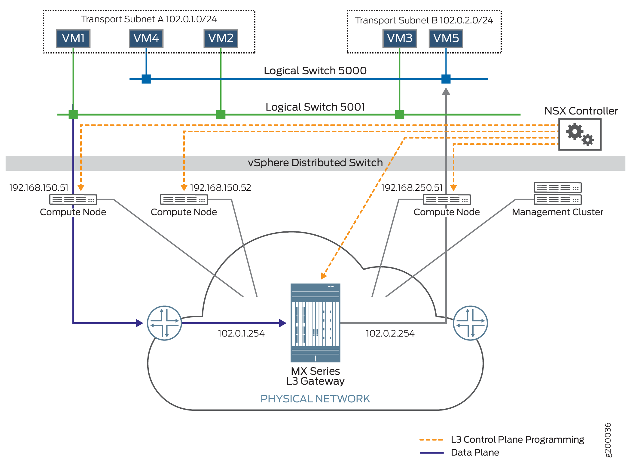
Figure 1 shows a data center
topology is shown in . A VDS provides the centralized interface for
configuring, monitoring and administering virtual machine access switching.
A VDS is a software switch present in the NSX compute node. Logical
switches represent VXLAN in the NSX-V solution. Two logical switches
are connected to this VDS. Each logical switch has its own bridge
domain in the MX Series router. The logical switches support five
VMs. Logical Switch 5000 supports VM4 and VM 5. Logical Switch 5001
supports VM1, VM2, and VM3. Each logical switch has its own bridge
domain. Two integrated routing and bridging (IRB) interfaces are associated
with these bridge domains and assist in the transfer of packets from
one bridge domain to the other through the MX Series router, acting
as the Layer 3 gateway. Logical Switch 5000 uses irb.1,
and Logical Switch 5001 uses irb.2.
There are three servers in this data center:
Server 192.168.150.51 supports VM1 and VM4
Server 192.168.150.52 supports VM2
Server 192.168.250.51 supports VM3 and VM5
The management cluster contains an NSX controller and an NSX manager. The NSX controller maintains the runtime space and distributes information to the compute nodes. When a VM is brought up on a compute node, the compute node sends information about the VM, such as MAC and IP addresses, to the NSX controller. The NSX controller then pushes this information to all the servers. The NSX manager handles the management plane, supporting the API and the configuration. The NSX manager provisions and manages the network, network services, and VXLAN preparation.
Topology
In Figure 2, a Layer 2 port is created and looped on the MX Series router. This is done in order to bring up the IRB interfaces that map the MX Series router to the NSX controller.
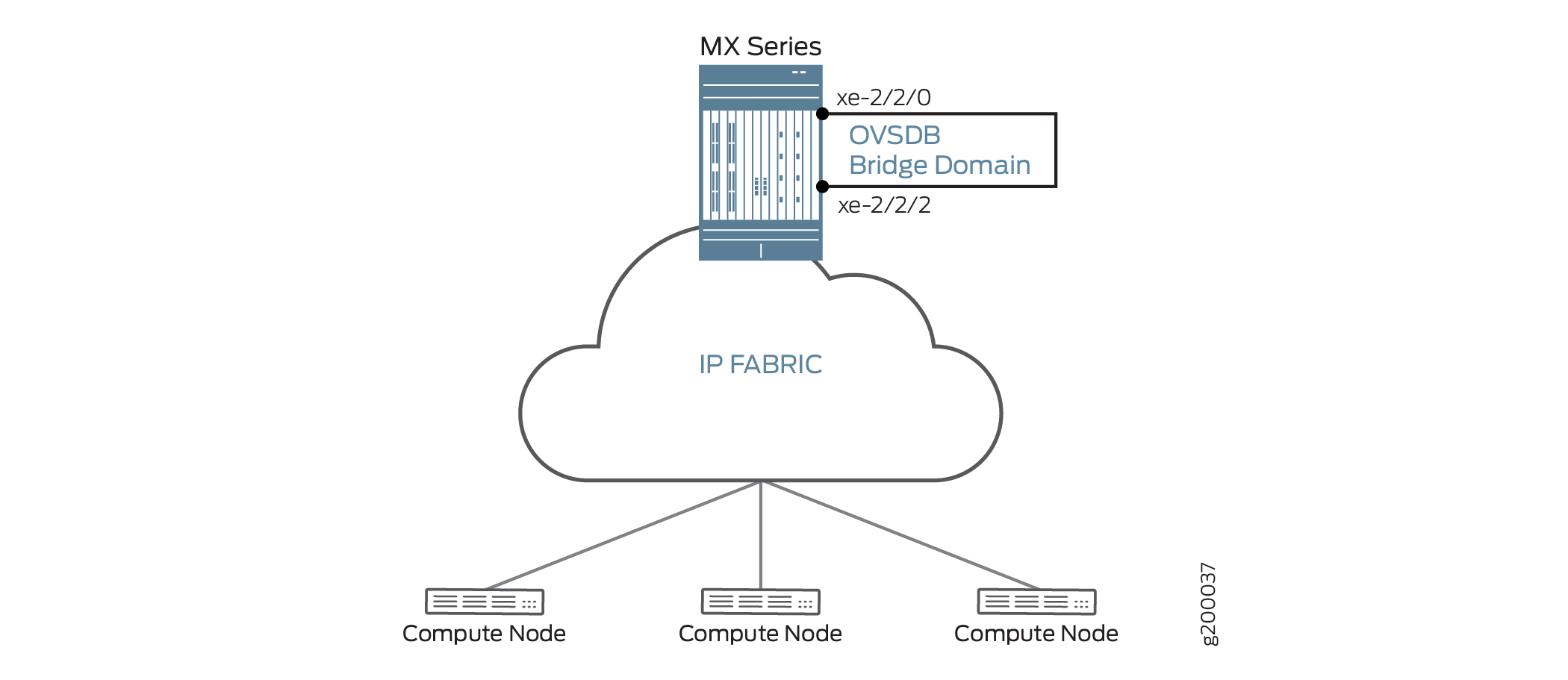
In this example, VM1 will send packets to VM5 using the MX Series router to do the inter-VXLAN translation. The router removes the VXLAN5001 header, encapsulates the packet with VXLAN 5000 header information, then sends the packet to VM5. VM1 uses the router to send a packet to VM5 (in another bridge domain) because it learns this information comes from the NSX controller. All hosts learn from the NSX Controller that VM5 is in the bridge domain of Logical Switch 5000 and therefore, must go through the gateway to reach that bridge domain.
Configuration
Procedure
CLI Quick Configuration
To quickly configure an MX Series router to act as a Layer 3 gateway, copy the following commands and paste them into the switch terminal window:
set bridge-domains a35fe7f7-fe82-37b4-b69a-0af4244d1fca vlan-id 1
set bridge-domains a35fe7f7-fe82-37b4-b69a-0af4244d1fca routing-interface irb.1
set bridge-domains a35fe7f7-fe82-37b4-b69a-0af4244d1fca vxlan ovsdb-managed
set bridge-domains a35fe7f7-fe82-37b4-b69a-0af4244d1fca vxlan vni 5000
set bridge-domains 03b264c5-9540-3666-a34a-c75d828439bc vlan-id 2
set bridge-domains 03b264c5-9540-3666-a34a-c75d828439bc routing-interface irb.2
set bridge-domains 03b264c5-9540-3666-a34a-c75d828439bc ovsdb-managed
set bridge-domains 03b264c5-9540-3666-a34a-c75d828439bc vni 5001
set interfaces xe-2/0/2 flexible-vlan-tagging
set interfaces xe-2/0/2 encapsulation flexible-ethernet-services
set interfaces xe-2/0/2 unit 1 family bridge interface-mode trunk
set interfaces xe-2/0/2 unit 1 family bridge vlan-id-list 1
set interfaces xe-2/0/2 unit 2 family bridge interface-mode trunk
set interfaces xe-2/0/2 unit 2 family bridge vlan-id-list 2
set interfaces irb unit 1 family inet address 102.0.1.254/24
set interfaces irb unit 2 family inet address 102.0.2.254/24
set protocols ovsdb interfaces xe-2/0/2.1
set protocols ovsdb interfaces xe-2/0/2.2
Step-by-Step Procedure
The following example requires you to navigate various levels in the configuration hierarchy. For information about navigating the CLI, see Using the CLI Editor in Configuration Mode in the CLI User Guide.
To configure an MX Series router to act as a Layer 3 gateway:
-
Specify the bridge domain configuration. The bridge domain name must be the universally unique identifier (UUID) of the logical switch created in the NSX manager (in this topology, logical switches 5000 and 5001). Use the routing-interface statement to specify a routing interface to include in the bridge domain. Include the Virtual Extensible LAN (VXLAN) identifier number using the vni statement. Add the ovsdb-managed statement to specify that MX router will use the Open vSwitch Database (OVSDB) management protocol to learn about the hardware VTEPs in the VXLAN and the MAC addresses learned by the hardware VTEPs.
To locate the UUID number, issue the show ovsdb logical-switch command. The UUID number is found in the
Logical Switch Namefield:user@host> show ovsdb logical-switch Logical switch information: Logical Switch Name: a35fe7f7-fe82-37b4-b69a-0af4244d1fca Flags: Created by both VNI: 5000 Logical switch information: Logical Switch Name: 03b264c5-9540-3666-a34a-c75d828439bc Flags: Created by both VNI: 5001
[edit bridge-domains]
user@switch# set a35fe7f7-fe82-37b4-b69a-0af4244d1fca vlan-id 1
user@switch# set a35fe7f7-fe82-37b4-b69a-0af4244d1fca routing-interface irb.1
user@switch# set a35fe7f7-fe82-37b4-b69a-0af4244d1fca ovsdb-managed
user@switch# set a35fe7f7-fe82-37b4-b69a-0af4244d1fca vni 5000

[edit bridge-domains]
user@switch# set 03b264c5-9540-3666-a34a-c75d828439bc vlan-id 2
user@switch# set 03b264c5-9540-3666-a34a-c75d828439bc routing-interface irb.2
user@switch# set 03b264c5-9540-3666-a34a-c75d828439bc vxlan ovsdb-managed
user@switch# set 03b264c5-9540-3666-a34a-c75d828439bc vxlan vni 5001
Configure the Layer 2 port.
[edit interfaces]
user@switch# set xe-2/0/2 flexible-vlan-tagging
user@switch# set xe-2/0/2 encapsulation flexible-ethernet-services
user@switch# set xe-2/0/2 unit 1 family bridge interface-mode trunk
user@switch# set xe-2/0/2 unit 1 family bridge vlan-id-list1
user@switch# set xe-2/0/2 unit 2family bridge interface-mode trunk
user@switch# set xe-2/0/2 unit 2family bridge vlan-id-list2
Configure the IRB interfaces to route traffic between VXLAN domains
[edit interfaces]
user@switch# set irb unit 1 family inet address 102.0.1.254/24
user@switch# set irb unit 2family inet address 102.0.2.254/24
Configure the interfaces for the OVSDB protocol:
Note:The interfaces must also be configured on the NSX controller.
[edit protocols]
user@switch# set ovsdb interfaces xe-2/0/2.1
user@switch# set ovsdb interfaces xe-2/0/2.2
Results
From configuration mode, confirm your configuration
by entering the show bridge domain command for bridge domains a35fe7f7-fe82-37b4-b69a-0af4244d1fca and 03b264c5-9540-3666-a34a-c75d828439bci:
[edit]
user@switch# show bridge domain a35fe7f7-fe82-37b4-b69a-0af4244d1fca
May 04 16:28:04
domain-type bridge;
vlan-id 1;
routing-interface irb.1;
vxlan {
    ovsdb-managed;
    decapsulate-accept-inner-vlan;
    vni 5000;
}

user@switch# show bridge domain 03b264c5-9540-3666-a34a-c75d828439bc
May 04 16:28:04
domain-type bridge;
vlan-id 2;
routing-interface irb.2;
vxlan {
    ovsdb-managed;
    decapsulate-accept-inner-vlan;
    vni 5001;
}
If you are done configuring the devices, enter commit from configuration mode.
Verification
Confirm that the configuration is working properly.
- Checking the Server IP Address and the VM MAC Address
- Checking the NSX Controller Connection
- Checking the OVSDB-Managed Interfaces
Checking the Server IP Address and the VM MAC Address
Purpose
Verify that the server IP address and the VM MAC address are correct.
Action
Issue the show ovsdb mac logical-switch command,
and verify the server IP address and the VM MAC address being used
by the bridge domain.
user@switch> show ovsdb mac logical-switch a35fe7f7-fe82-37b4-b69a-0af4244d1fca
May 04 16:30:01
Logical Switch Name: a35fe7f7-fe82-37b4-b69a-0af4244d1fca
  Mac                    IP                 Encapsulation      Vtep
  Address                Address                               Address
  ff:ff:ff:ff:ff:ff      0.0.0.0            Vxlan over Ipv4    10.255.178.171
  00:21:59:ad:27:f0      0.0.0.0            Vxlan over Ipv4    10.255.178.171
  00:50:56:83:cb:b3      0.0.0.0            Vxlan over Ipv4    192.168.150.51
  ff:ff:ff:ff:ff:ff      0.0.0.0            Vxlan over Ipv4    10.10.0.2
    -                                                          11.11.0.2
Meaning
The results displayed by the show ovsdb mac logical-switch
a35fe7f7-fe82-37b4-b69a-0af4244d1fca, command output show the
server IP address is 192.168.150.51 and the VM MAC address
is 00:50:56:83:cb:b3.
Checking the NSX Controller Connection
Purpose
Verify that the connection with the NSX controller is up.
Action
Issue the show ovsdb controller command,
and verify that the controller connection state is up.
user@switch> show ovsdb controller
May 04 16:32:21
VTEP controller information:
Controller IP address: 25.25.25.25
Controller protocol: ssl
Controller port: 6640
Controller connection: up
Controller seconds-since-connect: 253770
Controller seconds-since-disconnect: 167262
Controller connection status: backoff

Controller IP address: 25.25.25.26
Controller protocol: ssl
Controller port: 6640
Controller connection: up
Controller seconds-since-connect: 253767
Controller seconds-since-disconnect: 167293
Controller connection status: backoff
Meaning
The output shows that the connection state of the NSX
controller is up, in addition to other information about
the controller. When this connection is up, OVSDB is enabled on the
Juniper Networks device.
Checking the OVSDB-Managed Interfaces
Purpose
Verify the interfaces mapped to OVSDB.
Action
Issue the show ovsdb interface command, and
verify the interfaces managed by OVSDB.
user@switch> show ovsdb interface
May 04 16:33:23
Interface              VLAN ID         Bridge-domain
evpn
irb.1                  0               a35fe7f7-fe82-37b4-b69a-0af4244d1fca
irb.2                  0               03b264c5-9540-3666-a34a-c75d828439bc
l3
vpls
xe-2/0/2.1             1               a35fe7f7-fe82-37b4-b69a-0af4244d1fca
xe-2/0/2.2             2               03b264c5-9540-3666-a34a-c75d828439bc
Meaning
The show ovsdb interface command shows that irb.1 and xe-2/0/2.1 are being managed in the a35fe7f7-fe82-37b4-b69a-0af4244d1fca bridge domain, and irb.2 and xe-2/0/2.2 are being managed in the 03b264c5-9540-3666-a34a-c75d828439bc bridge domain.