Example: Passing Traffic Between Data Centers with DCI in an OVSDB-Managed Network with MX Series Routers
You can configure an MX Series 5G Universal Routing Platform to route Virtual Extensible LAN (VXLAN) traffic from a local data center in an OVSDB-managed network to a remote data center using Data Center Interconnect (DCI). DCI connects data centers in an enterprise IT environment to share resources or pass traffic between one another.
In this example, an MX Series router is used as the DCI for traffic to pass from a bridge domain in a local data center to a remote data center.
Requirements
This example uses the following hardware and software components:
An MX Series router
Junos OS Release 17.2R1 or later
A VMware vSphere Distributed Switch (VDS)
Five virtual machines (VMs)
An NSX controller
An NSX manager
Three servers
Overview and Topology
Figure 1 shows a data center
topology. A VDS provides the centralized interface for configuring,
monitoring, and administering virtual machine access switching. Two
logical switches are connected to this VDS. The logical switches support
five VMs. Logical Switch 5000 supports VM4 and VM5. Logical Switch
5001 supports VM1, VM2, and VM3. Each logical switch has its own bridge
domain. Two integrated routing and bridging (IRB) interfaces are associated
with these bridge domains and assist in the transfer of packets from
one bridge domain to the other through the MX Series router, acting
as the Layer 3 gateway. Logical Switch 5000 uses irb.1,
and Logical Switch 5001 uses irb.2.
There are three servers in this data center:
Server 192.168.150.51 supports VM1 and VM4
Server 192.168.150.52 supports VM2
Server 192.168.250.51 supports VM3 and VM5
Topology
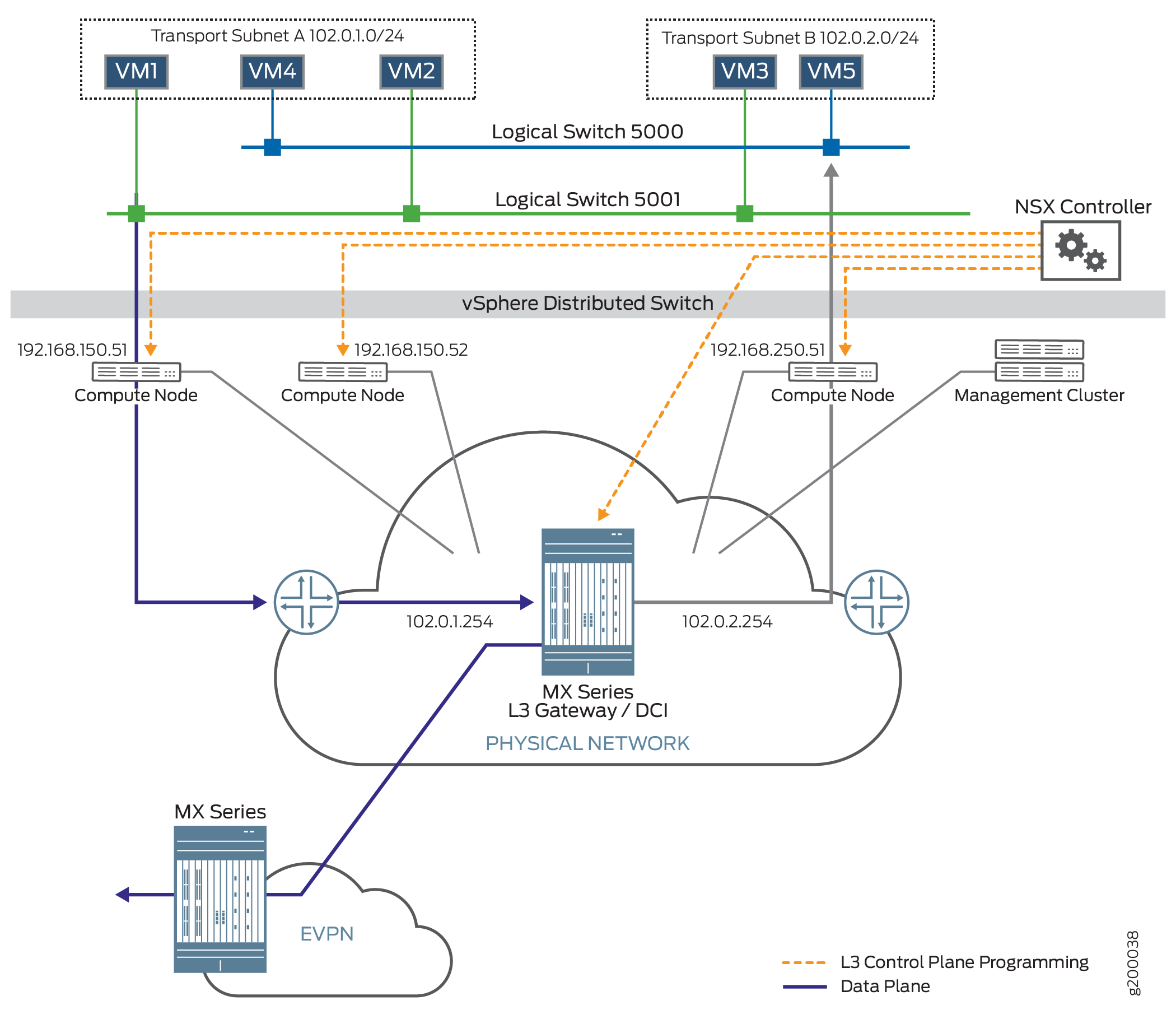
The management cluster contains an NSX controller and an NSX manager. The NSX controller maintains the runtime space and distributes information to the compute nodes. When a VM is brought up on a compute node, the compute node sends information about the VM, such as MAC and IP addresses, to the NSX controller. The NSX controller then pushes this information to all the servers. The NSX manager handles the management plane, supporting the API and the configuration. It provisions and manages the network, network services, and VXLAN preparation.
In this topology, a Layer 2 port is created and looped on the MX Series router. One end of the Layer 2 port is in the VXLAN bridge domain and the other end is in the EVPN routing instance. Figure 2 shows interface xe-2/0/2 looped to interface xe-2/3/0. Interface xe-2/0/2 is part of the VXLAN bridge domain and interface xe-2/3/0 is part of the EVPN routing instance. Interface xe-2/0/2 ifls are also added in the NSX manager. Using this topology and configuration, the IRB interfaces that map the MX Series router to the NSX controller are brought up. Traffic travels from the local data center to the remote data center by means of a virtual routing instance.
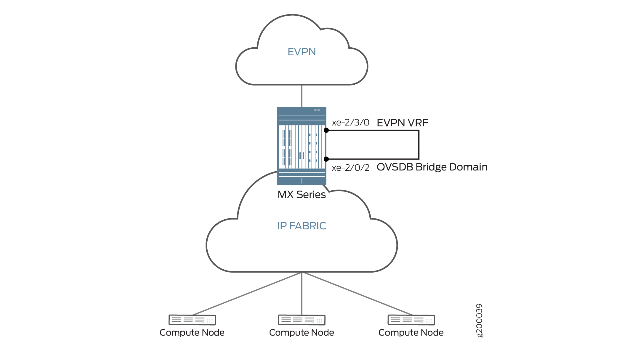
In this example, VM1 sends packets from the local data center for delivery to the remote data center. The packets go through the Layer 3 gateway on the MX Series router. There the router de-encapsulates the VXLAN5001 header from the packet and sends the packet out through an EVPN to the remote data center.
Configuration
Procedure
CLI Quick Configuration
To quickly configure an MX Series router to act as a DCI and enable VXLAN traffic to travel from a local data center to a remote data center, copy the following commands and paste them into the switch terminal window:
[edit]
set bridge-domains a35fe7f7-fe82-37b4-b69a-0af4244d1fca vlan-id 1
set bridge-domains a35fe7f7-fe82-37b4-b69a-0af4244d1fca vxlan ovsdb-managed
set bridge-domains a35fe7f7-fe82-37b4-b69a-0af4244d1fca vxlan vni 5000
set bridge-domains 03b264c5-9540-3666-a34a-c75d828439bc vlan-id 2
set bridge-domains 03b264c5-9540-3666-a34a-c75d828439bc ovsdb-managed
set bridge-domains 03b264c5-9540-3666-a34a-c75d828439bc vni 5001
set interfaces xe-2/3/0 flexible-vlan-tagging
set interfaces xe-2/3/0 encapsulation flexible-ethernet-services
set interfaces xe-2/3/0 unit 1 family bridge interface-mode trunk
set interfaces xe-2/3/0 unit 1 family bridge vlan-id-list 1
set interfaces xe-2/3/0 unit 2 family bridge interface-mode trunk
set interfaces xe-2/3/0 unit 2 family bridge vlan-id-list 2
set interfaces xe-2/0/2 flexible-vlan-tagging
set interfaces xe-2/0/2 encapsulation flexible-ethernet-services
set interfaces xe-2/0/2 unit 1 family bridge interface-mode trunk
set interfaces xe-2/0/2 unit 1 family bridge vlan-id-list 1
set interfaces xe-2/0/2 unit 2 family bridge interface-mode trunk
set interfaces xe-2/0/2 unit 2 family bridge vlan-id-list 2
set interfaces irb unit 1 family inet address 102.0.1.254/24
set interfaces irb unit 2 family inet address 102.0.2.254/24
set routing-instances evpn1 instance-type virtual-switch
set routing-instances evpn1 interface xe-2/3/0.1
set routing-instances evpn1 interface xe-2/3/0.2
set routing-instances evpn1 route-distinguisher 64512:1
set routing-instances evpn1 vrf-target target:64512:1
set routing-instances evpn1 protocols evpnextended-vlan-list 1-2
set routing-instances evpn1 bridge-domains vlan1 domain-type bridge
set routing-instances evpn1 bridge-domains vlan1 vlan-id 1
set routing-instances evpn1 bridge-domains vlan1 routing-interface irb.1
set routing-instances evpn1 bridge-domains vlan2 domain-type bridge
set routing-instances evpn1 bridge-domains vlan2 vlan-id 2
set routing-instances evpn1 bridge-domains vlan2 routing-interface irb.2
set protocols ovsdb interfaces xe-2/0/2.1
set protocols ovsdb interfaces xe-2/0/2.2
Step-by-Step Procedure
The following example requires you to navigate various levels in the configuration hierarchy. For information about navigating the CLI, see Using the CLI Editor in Configuration Mode in the CLI User Guide.
To configure an MX Series router as a DCI to transport traffic from a local data center to a remote data center:
Specify the bridge domain configuration. The bridge domain name must be the universally unique identifier (UUID) of the logical switch created in NSX manager (in this topology, logical switches 5000 and 5001). Include the VXLAN identifier number using the vni statement. Add the ovsdb-managed statement to specify that the MX Series router will use the Open vSwitch Database (OVSDB) management protocol to learn about the hardware VTEPs in the VXLAN and the MAC addresses learned by the hardware VTEPs.
To locate the UUID number, issue the show ovsdb logical-switch command. The UUID number is found in the Logical Switch Name field.
user@host> show ovsdb logical-switch
Logical switch information:
Logical Switch Name: a35fe7f7-fe82-37b4-b69a-0af4244d1fca
Flags: Created by both
VNI: 5000

Logical switch information:
Logical Switch Name: 03b264c5-9540-3666-a34a-c75d828439bc
Flags: Created by both
VNI: 5001

[edit bridge-domains]
user@switch# set a35fe7f7-fe82-37b4-b69a-0af4244d1fca vlan-id 1
user@switch# set a35fe7f7-fe82-37b4-b69a-0af4244d1fca vxlan ovsdb-managed
user@switch# set a35fe7f7-fe82-37b4-b69a-0af4244d1fca vxlan vni 5000
user@switch# set 03b264c5-9540-3666-a34a-c75d828439bc vlan-id 2
user@switch# set 03b264c5-9540-3666-a34a-c75d828439bc vxlan ovsdb-managed
user@switch# set 03b264c5-9540-3666-a34a-c75d828439bc vxlan vni 5001
Configure the looped Layer 2 port.
[edit interfaces]
user@switch# set xe-2/3/0 flexible-vlan-tagging
user@switch# set xe-2/3/0 encapsulation flexible-ethernet-services
user@switch# set xe-2/3/0 unit 1 family bridge interface-mode trunk
user@switch# set xe-2/3/0 unit 1 family bridge vlan-id-list1
user@switch# set xe-2/3/0 unit 2family bridge interface-mode trunk
user@switch# set xe-2/3/0 unit 2family bridge vlan-id-list2
Configure the MX Series router port that is connected to the VXLAN bridge.
[edit interfaces]
user@switch# set xe-2/0/2 flexible-vlan-tagging
user@switch# set xe-2/0/2 encapsulation flexible-ethernet-services
user@switch# set xe-2/0/2 unit 1 family bridge interface-mode trunk
user@switch# set xe-2/0/2 unit 1 family bridge vlan-id-list1
user@switch# set xe-2/0/2 unit 2family bridge interface-mode trunk
user@switch# set xe-2/0/2 unit 2family bridge vlan-id-list2
Configure the IRB interfaces to route traffic between the VXLAN domains.
[edit interfaces]
user@switch# set irb unit 1 family inet address 102.0.1.254/24
user@switch# set irb unit 2family inet address 102.0.2.254/24
Configure the virtual switch routing instance to the remote data center.
[edit routing-instances]
user@switch# set evpn1 instance-type virtual-switch
user@switch# set evpn1 interface xe-2/3/0.1
user@switch# set evpn1 interface xe-2/3/0.2
user@switch# set evpn1 route-distinguisher 64512:1
user@switch# set evpn1 vrf-target target:64512:1
user@switch# set evpn1 protocols evpnextended-vlan-list 1-2
user@switch# set evpn1 bridge-domains vlan1 domain-type bridge
user@switch# set evpn1 bridge-domains vlan1 vlan-id 1
user@switch# set evpn1 bridge-domains vlan1 routing-interface irb.1
user@switch# set evpn1 bridge-domains vlan2 domain-type bridge
user@switch# set evpn1 bridge-domains vlan2 vlan-id 2
user@switch# set evpn1 bridge-domains vlan2 routing-interface irb.2
Configure the OVSDB protocol on the ports. You must also add these same ports as part of the logical switch in NSX manager. When they are added, NSX manager identifies which port on the MX Series router is mapped to the respective VXLAN VNI. In this case VXLAN VNI 5000 is mapped to xe-2/0/2.1 and VXLAN VNI 5001 is mapped to xe-2/0/2.2.
[edit protocols]
user@switch# set ovsdb interfaces xe-2/0/2.1
user@switch# set ovsdb interfaces xe-2/0/2.2
Results
From configuration mode, confirm your configuration
by entering the show bridge domain command for bridge domains a35fe7f7-fe82-37b4-b69a-0af4244d1fca and 03b264c5-9540-3666-a34a-c75d828439bc
user@switch# show bridge domain a35fe7f7-fe82-37b4-b69a-0af4244d1fca
May 04 16:27:35
domain-type bridge;
vlan-id 1;
routing-interface irb.1;
vxlan {
    ovsdb-managed;
    vni 5000;
    decapsulate-accept-inner-vlan;
    vni 5000;
}

user@switch# show bridge domain 03b264c5-9540-3666-a34a-c75d828439bc
May 04 16:28:04
domain-type bridge;
vlan-id 2;
routing-interface irb.2;
vxlan {
    ovsdb-managed;
    vni 5001;
    decapsulate-accept-inner-vlan;
    vni 5000;
}
If you are done configuring the devices, enter commit from configuration mode.
Verification
To confirm that the configuration is working properly, perform these tasks:
- Checking the Server IP Address and the VM MAC Address
- Checking the NSX Controller Connection
- Checking the OVSDB-Managed Interfaces
- Checking the Routing Instance for the EVPN
- Checking the IRBs for the EVPN Routing Instance
Checking the Server IP Address and the VM MAC Address
Purpose
Verify that the server IP address and the VM MAC address are correct.
Action
Issue the show ovsdb mac logical-switch command,
and verify the server IP address and the VM MAC address being used
by the bridge domain.
user@switch> show ovsdb mac logical-switch a35fe7f7-fe82-37b4-b69a-0af4244d1fca
May 04 16:30:01
Logical Switch Name: a35fe7f7-fe82-37b4-b69a-0af4244d1fca
  Mac                    IP                 Encapsulation      Vtep
  Address                Address                               Address
  ff:ff:ff:ff:ff:ff      0.0.0.0            Vxlan over Ipv4    10.255.178.171
  00:21:59:ad:27:f0      0.0.0.0            Vxlan over Ipv4    10.255.178.171
  00:50:56:83:cb:b3      0.0.0.0            Vxlan over Ipv4    192.168.150.51
  ff:ff:ff:ff:ff:ff      0.0.0.0            Vxlan over Ipv4    10.10.0.2
    -                                                          11.11.0.2
Meaning
The results displayed by the show ovsdb mac logical-switch
a35fe7f7-fe82-37b4-b69a-0af4244d1fca, command output show the
server IP address is 192.168.150.51 and the VM MAC address
is 00:50:56:83:cb:b3.
Checking the NSX Controller Connection
Purpose
Verify that the connection with the NSX controller is up.
Action
Issue the show ovsdb controller command,
and verify that the controller connection state is up.
user@switch> show ovsdb controller
May 04 16:32:21
VTEP controller information:
Controller IP address: 25.25.25.25
Controller protocol: ssl
Controller port: 6640
Controller connection: up
Controller seconds-since-connect: 253770
Controller seconds-since-disconnect: 167262
Controller connection status: backoff

Controller IP address: 25.25.25.26
Controller protocol: ssl
Controller port: 6640
Controller connection: up
Controller seconds-since-connect: 253767
Controller seconds-since-disconnect: 167293
Controller connection status: backoff
Meaning
The output shows that the connection state of the NSX
controller is up, in addition to other information about
the controller. When this connection is up, OVSDB is enabled on the
Juniper Networks device.
Checking the OVSDB-Managed Interfaces
Purpose
Verify the interfaces mapped to OVSDB.
Action
Issue the show ovsdb interface command, and
verify the interfaces managed by OVSDB.
user@switch> show ovsdb interface
May 04 16:33:23
Interface              VLAN ID         Bridge-domain
evpn
irb.1                  0               a35fe7f7-fe82-37b4-b69a-0af4244d1fca
irb.2                  0               03b264c5-9540-3666-a34a-c75d828439bc
l3
vpls
xe-2/0/2.1             1               a35fe7f7-fe82-37b4-b69a-0af4244d1fca
xe-2/0/2.2             2               03b264c5-9540-3666-a34a-c75d828439bc
Meaning
The show ovsdb interface command shows that irb.1 and xe-2/0/2.1 are being managed in the a35fe7f7-fe82-37b4-b69a-0af4244d1fca bridge domain, and irb.2 and xe-2/0/2.2 are being managed in the 03b264c5-9540-3666-a34a-c75d828439bc bridge domain.
Checking the Routing Instance for the EVPN
Purpose
Verify that the IRB interfaces are configured and active for the EVPN.
Action
Issue the show evpn instance command, and
verify the EVPN routing instance information.
user@switch> show evpn instance evpn1
May 11 10:56:45
                            Intfs       IRB intfs         MH      MAC addresses
Instance                    Total   Up  Total   Up  Nbrs  ESIs    Local  Remote
evpn1                           2    2      2    2     0     0        2       0
Issue the show evpn database instance evpn1 command, and verify the Active Source information.
user@switch> show evpn database instance evpn1
May 11 10:58:24
Instance: evpn1
VLAN  DomainId  MAC address        Active source                  Timestamp        IP address
3               00:21:59:ad:27:f0  irb.1                          May 09 16:43:54  102.0.1.254
4               00:21:59:ad:27:f0  irb.2                          May 09 16:43:54  102.0.2.254
Meaning
The results displayed by the show evpn instance
evpn1 command verify the routing instance and the field IRB intfs shows that two IRB interfaces are up. The results
displayed by the show evpn database instance evpn1 command
show that under the Active Source field, irb.1 and irb.2 are traffic sources.
Checking the IRBs for the EVPN Routing Instance
Purpose
Verify the IRB interfaces for the EVPN.
Action
Issue the show evpn database instance command,
and verify the EVPN routing instance information.
user@switch> show evpn database instance evpn1
May 11 10:58:24
Instance: evpn1
VLAN  DomainId  MAC address        Active source                  Timestamp        IP address
3               00:21:59:ad:27:f0  irb.1                          May 09 16:43:54  102.0.1.254
4               00:21:59:ad:27:f0  irb.2                          May 09 16:43:54  102.0.2.254
Meaning
The results displayed by the show evpn database
instance evpn1 command show the EVPN1 instance and verifies
under IRB intfs that two IRB interfaces are up and running.