Example: Configure Multiple Independent Instances of OSPFv2 with Segment Routing
Use this example to configure multiple IGP instances of OSPFv2 with segment routing.
Our content testing team has validated and updated this example.
|
Reading Time |
30 minutes |
|
Configuration Time |
20 minutes |
Example Prerequisites
|
Hardware requirements |
Three MX Series routers. |
|
Software requirements |
Junos OS Release 24.4R1 or later running on all devices. |
Before You Begin
|
Benefits |
Configuring multiple independent instances of OSPFv2 with segment routing enhances network flexibility, scalability, and control over traffic engineering, especially in large and complex networks. |
|
Know more |
Functional Overview
|
Technologies used |
|
|
Primary verification tasks |
|
Topology Overview
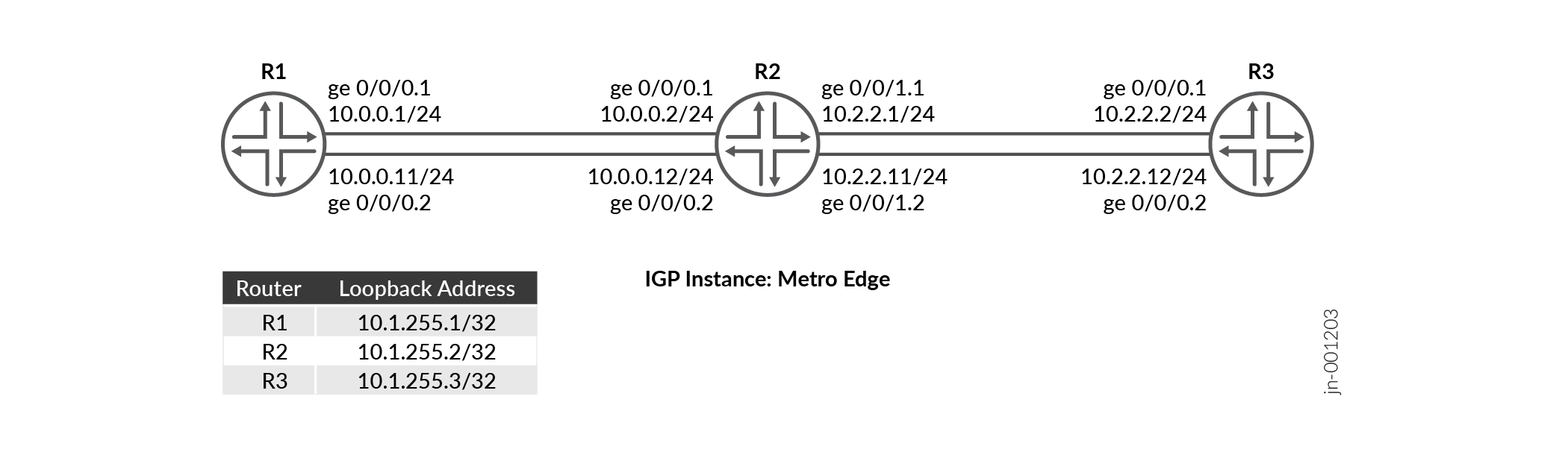
This configuration example depicts three devices R1, R2, and R3. There are two
sub-interfaces configured between device R1 and device R2 and between device R2 and
device R3. Each device runs multiple OSPF instances with segment routing enabled. We
configure SR-MPLS to provide path control through the network. There are OSPF
instances named metro-edge running on each of the two subinterfaces
of the devices.
|
Hostname |
Role |
Function |
|---|---|---|
|
R1, R2, and R3 |
The devices have multi-instance OSPF configured on the subinterfaces, with segment routing enabled. |
The devices participate in OSPF multi-instances, advertise routes, and forward traffic using prefix-SIDs to other devices. |
Topology Illustration
R2 Configuration Steps
For complete sample configurations on R2, see: Appendix 1: Set Commands on All Devices
This section highlights the main configuration tasks needed to configure the R0 device for this example.
-
Configure the basic device settings such as hostname,
enhanced-ipmode, IPv4 addresses on the logical units of the device interfaces.Configure the loopback interface with an IP address and enable MPLS.
Configure the router ID and autonomous system (AS) number to propagate routing information within a set of routing devices that belong to the same AS.
Enable VLAN tagging and configure the logical units of both the interfaces with different VLAN IDs.
Enable MPLS on each logical unit. Configure the maximum number of MPLS labels that can be applied to outgoing packets on logical units of each interface.
Define a policy to load balance packets and apply the per-packet policy to enable load balancing of traffic.
Configure a policy statement that matches routes based on the exact prefix and assign a segment identifier to the matched route.
Configure MPLS traffic engineering, segment routing global block (SRGB) label range at the
edit protocol mplshierarchy level to ensure the labels are more predictable across segment routing domain, MPLS label range to assign labels from the configured srgb labels for the links.[edit] set system host-name R2 set chassis network-services enhanced-ip set interfaces ge-0/0/0 unit 1 family inet address 10.0.0.2/24 set interfaces ge-0/0/0 unit 2 family inet address 10.0.0.12/24 set interfaces ge-0/0/1 unit 1 family inet address 10.2.2.1/24 set interfaces ge-0/0/1 unit 2 family inet address 10.2.2.11/24
[edit]
set interfaces lo0 unit 0 family inet address 10.1.255.2/32
set interfaces lo0 unit 0 family mpls
[edit]
set routing-options router-id 10.1.255.2
set routing-options autonomous-system 100
[edit]
set interfaces ge-0/0/0 vlan-tagging
set interfaces ge-0/0/0 unit 1 vlan-id 1
set interfaces ge-0/0/0 unit 2 vlan-id 2
set interfaces ge-0/0/1 vlan-tagging
set interfaces ge-0/0/1 unit 1 vlan-id 1
set interfaces ge-0/0/1 unit 2 vlan-id 2
[edit]
set interfaces ge-0/0/0 unit 1 family mpls maximum-labels 5
set interfaces ge-0/0/0 unit 2 family mpls maximum-labels 5
set interfaces ge-0/0/1 unit 1 family mpls maximum-labels 5
set interfaces ge-0/0/1 unit 2 family mpls maximum-labels 5
[edit]
set policy-options policy-statement pplb then load-balance per-packet
set policy-options policy-statement pplb then accept
set routing-options forwarding-table export pplb
[edit]
set policy-options policy-statement prefix-sid term 1 from route-filter 10.1.255.2/32 exact
set policy-options policy-statement prefix-sid term 1 then prefix-segment index 1001
set policy-options policy-statement prefix-sid term 1 then accept
[edit]
set protocols mpls traffic-engineering
set protocols mpls label-range srgb-label-range 800000 879999
set protocols mpls label-range static-label-range 60001 100000
set protocols mpls interface all
set protocols mpls interface fxp0.0 disable
Configure the
ospf-instancemetro-edgeon the subinterfaces (connecting from R2 to R1 and from R2 to R3).[edit] set protocols ospf-instance metro-edge area 0.0.0.0 interface all
Enable the OSPF
metro-edgeinstance to use segment routing with prefix-sids.[edit] set protocols ospf-instance metro-edge source-packet-routing prefix-segment prefix-sid
- Configure the IPv4 index value of the node
segment.
[edit]
set protocols ospf-instance metro-edge source-packet-routing node-segment ipv4-index 1
Configure the loopback address of the OSPF
metro-edgeinstance as passive and disable the management interface (fxp0.0).[edit] set protocols ospf-instance metro-edge area 0.0.0.0 interface lo0.0 passive set protocols ospf-instance metro-edge area 0.0.0.0 interface fxp0.0 disable
Verification
| Command | Verification Task |
|---|---|
| show route protocol ospf table inet.0 extensive |
|
| show ospf spring sid-database igp-instance igp-instance | Verify the OSPF segment routing database for the OSPF instance. |
| show ospf neighbor igp-instance igp-instance | Verify neighbors for the specific OSPF instance. |
| show ospf database igp-instance igp-instance |
Verify the OSPF advertisement entries in the OSPF link-state database (LSDB) associated with the IGP instance. |
| show ospf interface igp-instance igp-instance | Verify the interfaces mapped to the IGP instance. |
| show ospf route igp-instance igp-instance | Verify the routes and OSPF instance mapping information of R1 and R3. |
- Verify the Routing Table
- Verify OSPF Advertisements
- Verify the Routes in the OSPF Routing Table
- Verify the OSPF segment routing database
- Verify the OSPF Interfaces
- Verify the OSPF Neighbor
Verify the Routing Table
Purpose
Verify the route entries in the routing table
Action
From operational mode, run the show route table inet.0
route-destination address extensive command.
user@R2>show route protocol ospf table inet.0 10.1.255.1 extensive
inet.0: 19 destinations, 21 routes (19 active, 0 holddown, 0 hidden)
10.1.255.1/32 (1 entry, 1 announced)
TSI:
KRT in-kernel 10.1.255.1/32 -> {list:10.0.0.1, 10.0.0.11}
        *OSPF   Preference: 10/10
                Next hop type: Router, Next hop index: 0
                Address: 0x8b32234
                Next-hop reference count: 2, Next-hop session id: 0
                Kernel Table Id: 0
                Next hop: 10.0.0.1 via ge-0/0/0.1, selected
                Session Id: 0
                Next hop: 10.0.0.11 via ge-0/0/0.2
                Session Id: 0
                State: <Active Int>
                Local AS:   100
                Age: 1w4d 16:01:19      Metric: 1
                Validation State: unverified
                Area: 0.0.0.0
                Task: OSPF-metro-edge
                Announcement bits (1): 0-KRT
                AS path: I
                Thread: junos-main

user@R2>show route protocol ospf table inet.0 10.1.255.3 extensive
inet.0: 19 destinations, 21 routes (19 active, 0 holddown, 0 hidden)
10.1.255.3/32 (1 entry, 1 announced)
TSI:
KRT in-kernel 10.1.255.3/32 -> {list:10.2.2.2, 10.2.2.12}
        *OSPF   Preference: 10/10
                Next hop type: Router, Next hop index: 0
                Address: 0x8b316f4
                Next-hop reference count: 2, Next-hop session id: 0
                Kernel Table Id: 0
                Next hop: 10.2.2.2 via ge-0/0/1.1, selected
                Session Id: 0
                Next hop: 10.2.2.12 via ge-0/0/1.2
                Session Id: 0
                State: <Active Int>
                Local AS:   100
                Age: 1w4d 16:13:55      Metric: 1
                Validation State: unverified
                Area: 0.0.0.0
                Task: OSPF-metro-edge
                Announcement bits (1): 0-KRT
                AS path: I
                Thread: junos-main
Meaning
The output illustrates that the loopback address of R1 (10.1.255.1) and the loopback address of R3 (10.1.255.2) is mapped to the OSPF igp-instance metro-edge as configured in R2.
Verify OSPF Advertisements
Purpose
Verify the OSPF advertisement entries in the OSPF link-state database (LSDB) associated with the IGP instance.
Action
From the operational mode, run the show ospf database igp-instance
igp-instance command.
user@R2>show ospf database igp-instance metro-edge
    OSPF database, Area 0.0.0.0
Type       ID               Adv Rtr           Seq      Age  Opt  Cksum  Len
Router   10.1.255.1       10.1.255.1       0x80000013  1110  0x22 0xe6e9  72
Router  *10.1.255.2       10.1.255.2       0x80000015  1084  0x22 0x7be2  96
Router   10.1.255.3       10.1.255.3       0x80000013  1585  0x22 0x491   72
Network *10.0.0.2         10.1.255.2       0x80000010  2959  0x22 0x6791  32
Network *10.0.0.12        10.1.255.2       0x80000010  2209  0x22 0x3eb   32
Network  10.2.2.2         10.1.255.3       0x80000010  2085  0x22 0x4ba6  32
Network  10.2.2.12        10.1.255.3       0x80000010  1085  0x22 0xe601  32
OpaqArea 7.0.0.1          10.1.255.1       0x80000012   193  0x22 0x8c0   44
OpaqArea*7.0.0.1          10.1.255.2       0x80000012   511  0x22 0x2a9b  44
OpaqArea 7.0.0.1          10.1.255.3       0x80000012   585  0x22 0x4c76  44
OpaqArea 8.0.0.1          10.1.255.1       0x80000010  2610  0x22 0x4683  48
OpaqArea*8.0.0.1          10.1.255.2       0x80000010  2584  0x22 0xac01  52
OpaqArea 8.0.0.1          10.1.255.3       0x80000010  2584  0x22 0x7d06  52
OpaqArea 8.0.0.2          10.1.255.1       0x80000010  1860  0x22 0x4f55  48
OpaqArea*8.0.0.2          10.1.255.2       0x80000011   334  0x22 0xf393  52
OpaqArea 8.0.0.2          10.1.255.3       0x80000011    84  0x22 0xc498  52
OpaqArea*8.0.0.3          10.1.255.2       0x80000010  1834  0x22 0x445a  48
OpaqArea*8.0.0.4          10.1.255.2       0x80000010  1459  0x22 0x4d2c  48
Meaning
Verify the Routes in the OSPF Routing Table
Purpose
Verify the routes in the OSPF routing table
Action
From the operational mode, run the show ospf route
command.
user@R2>show ospf route igp-instance metro-edge
Topology default Route Table:

Prefix             Path  Route      NH       Metric NextHop       Nexthop
                   Type  Type       Type            Interface     Address/LSP
10.1.255.1         Intra Router     IP            1 ge-0/0/0.1    10.0.0.1
                                                    ge-0/0/0.2    10.0.0.11
10.1.255.3         Intra Router     IP            1 ge-0/0/1.1    10.2.2.2
                                                    ge-0/0/1.2    10.2.2.12
10.0.0.0/24        Intra Network    IP            1 ge-0/0/0.1
                                                    ge-0/0/0.2
10.1.255.1/32      Intra Network    IP            1 ge-0/0/0.1    10.0.0.1
                                                    ge-0/0/0.2    10.0.0.11
10.1.255.2/32      Intra Network    IP            0 lo0.0
10.1.255.3/32      Intra Network    IP            1 ge-0/0/1.1    10.2.2.2
                                                    ge-0/0/1.2    10.2.2.12
10.2.2.0/24        Intra Network    IP            1 ge-0/0/1.1
                                                    ge-0/0/1.2
299840             Intra Network    Mpls          0 ge-0/0/0.2    10.0.0.11
299840 (S=0)       Intra Network    Mpls          0 ge-0/0/0.2    10.0.0.11
299856             Intra Network    Mpls          0 ge-0/0/0.1    10.0.0.1
299856 (S=0)       Intra Network    Mpls          0 ge-0/0/0.1    10.0.0.1
299904             Intra Network    Mpls          0 ge-0/0/1.2    10.2.2.12
299904 (S=0)       Intra Network    Mpls          0 ge-0/0/1.2    10.2.2.12
299920             Intra Network    Mpls          0 ge-0/0/1.1    10.2.2.2
299920 (S=0)       Intra Network    Mpls          0 ge-0/0/1.1    10.2.2.2
Meaning
The output on R2 shows the loopback addresses and OSPF instance mapping information of R1 and R3.
Verify the OSPF segment routing database
Purpose
Verify the OSPF segment routing database for the OSPF instance metro-edge.
Action
From the operational mode, run the show ospf spring sid-database
igp-instance igp-instance command.
user@R2>show ospf spring sid-database igp-instance metro-edge
    OSPF database, Area 0.0.0.0
SID     Prefix             Advertised-by    Route-type
1000    10.1.255.1/32      10.1.255.1       Intra-Area
1001    10.1.255.2/32      10.1.255.2       Intra-Area
1002    10.1.255.3/32      10.1.255.3       Intra-Area
Meaning
The output illustrates the multiple instances of OSPF (metro-edge) advertise different prefix-SIDs.
Verify the OSPF Interfaces
Purpose
Verify the status information about OSPF-instance enabled interfaces.
Action
From the operational mode, run the show ospf interface igp-instance
igp-instance command.
user@R2>show ospf interface igp-instance metro-edge
Interface           State   Area            DR ID           BDR ID          Nbrs
ge-0/0/0.1          DR      0.0.0.0         10.1.255.2      10.1.255.1         1
ge-0/0/0.2          DR      0.0.0.0         10.1.255.2      10.1.255.1         1
ge-0/0/1.1          DR      0.0.0.0         10.1.255.2      10.1.255.3         1
ge-0/0/1.2          DR      0.0.0.0         10.1.255.2      10.1.255.3         1
lo0.0               DRother 0.0.0.0         0.0.0.0         0.0.0.0            0
lo0.0               DRother 0.0.0.0         0.0.0.0         0.0.0.0            0
Meaning
The output shows the subinterfaces of R2 mapped to the OSPF instances (metro-edge).
Verify the OSPF Neighbor
Purpose
Verify the adjacencies between the configured links.
Action
From the operational mode, run the show ospf neighbor igp-instance
igp-instance command.
user@R2>show ospf neighbor igp-instance metro-edge
Address          Interface              State           ID               Pri  Dead
10.0.0.1         ge-0/0/0.1             Full            10.1.255.1       128    35
10.0.0.11        ge-0/0/0.2             Full            10.1.255.1       128    39
10.2.2.2         ge-0/0/1.1             Full            10.1.255.3       128    33
10.2.2.12        ge-0/0/1.2             Full            10.1.255.3       128    36
Meaning
Device R2 has established adjacency with Device R1 and Device R3 and as
indicated by the State output field which is Full.
Appendix 1: Set Commands on All Devices
To quickly configure this example, copy the following commands, paste them into a text file, remove any line breaks, change any details necessary to match your network configuration, and then copy and paste the commands into the CLI at the [edit] hierarchy level.
R1
set system host-name R1
set interfaces ge-0/0/0 unit 1 family inet address 10.0.0.1/24
set interfaces ge-0/0/0 unit 2 family inet address 10.0.0.11/24
set interfaces ge-0/0/0 unit 2 enable
set interfaces ge-0/0/0 vlan-tagging
set interfaces ge-0/0/0 unit 1 vlan-id 1
set interfaces ge-0/0/0 unit 2 vlan-id 2
set interfaces ge-0/0/0 unit 1 family mpls maximum-labels 5
set interfaces ge-0/0/0 unit 2 family mpls maximum-labels 5
set interfaces lo0 unit 0 family inet address 10.1.255.1/32
set interfaces lo0 unit 0 family mpls
set policy-options policy-statement pplb then load-balance per-packet
set policy-options policy-statement pplb then accept
set policy-options policy-statement prefix-sid term 1 from route-filter 10.1.255.1/32 exact
set policy-options policy-statement prefix-sid term 1 then prefix-segment index 1000
set policy-options policy-statement prefix-sid term 1 then accept
set routing-options router-id 10.1.255.1
set routing-options autonomous-system 100
set routing-options forwarding-table export pplb
set protocols mpls traffic-engineering
set protocols mpls label-range srgb-label-range 800000 879999
set protocols mpls label-range static-label-range 60001 100000
set protocols mpls interface all
set protocols mpls interface fxp0.0 disable
set protocols ospf-instance metro-edge source-packet-routing prefix-segment prefix-sid
set protocols ospf-instance metro-edge source-packet-routing node-segment ipv4-index 0
set protocols ospf-instance metro-edge area 0.0.0.0 interface all
set protocols ospf-instance metro-edge area 0.0.0.0 interface lo0.0 passive
set protocols ospf-instance metro-edge area 0.0.0.0 interface fxp0.0 disable
R2
set system host-name R2
set interfaces ge-0/0/0 unit 1 family inet address 10.0.0.2/24
set interfaces ge-0/0/0 unit 2 family inet address 10.0.0.12/24
set interfaces ge-0/0/1 unit 1 family inet address 10.2.2.1/24
set interfaces ge-0/0/1 unit 2 family inet address 10.2.2.11/24
set interfaces ge-0/0/0 vlan-tagging
set interfaces ge-0/0/0 unit 1 vlan-id 1
set interfaces ge-0/0/0 unit 2 vlan-id 2
set interfaces ge-0/0/1 vlan-tagging
set interfaces ge-0/0/1 unit 1 vlan-id 1
set interfaces ge-0/0/1 unit 2 vlan-id 2
set interfaces ge-0/0/0 unit 1 family mpls maximum-labels 5
set interfaces ge-0/0/0 unit 2 family mpls maximum-labels 5
set interfaces ge-0/0/1 unit 1 family mpls maximum-labels 5
set interfaces ge-0/0/1 unit 2 family mpls maximum-labels 5
set interfaces lo0 unit 0 family inet address 10.1.255.2/32
set interfaces lo0 unit 0 family mpls
set policy-options policy-statement pplb then load-balance per-packet
set policy-options policy-statement pplb then accept
set policy-options policy-statement prefix-sid term 1 from route-filter 10.1.255.2/32 exact
set policy-options policy-statement prefix-sid term 1 then prefix-segment index 1001
set policy-options policy-statement prefix-sid term 1 then accept
set routing-options router-id 10.1.255.2
set routing-options autonomous-system 100
set routing-options forwarding-table export pplb
set protocols mpls traffic-engineering
set protocols mpls label-range srgb-label-range 800000 879999
set protocols mpls label-range static-label-range 60001 100000
set protocols mpls interface all
set protocols mpls interface fxp0.0 disable
set protocols ospf-instance metro-edge source-packet-routing prefix-segment prefix-sid
set protocols ospf-instance metro-edge source-packet-routing node-segment ipv4-index 1
set protocols ospf-instance metro-edge area 0.0.0.0 interface all
set protocols ospf-instance metro-edge area 0.0.0.0 interface lo0.0 passive
set protocols ospf-instance metro-edge area 0.0.0.0 interface fxp0.0 disable
R3
set system host-name R3
set interfaces ge-0/0/0 unit 1 family inet address 10.2.2.2/24
set interfaces ge-0/0/0 unit 2 family inet address 10.2.2.12/24
set interfaces ge-0/0/0 vlan-tagging
set interfaces ge-0/0/0 unit 1 vlan-id 1
set interfaces ge-0/0/0 unit 2 vlan-id 2
set interfaces ge-0/0/0 unit 1 family mpls maximum-labels 5
set interfaces ge-0/0/0 unit 2 family mpls maximum-labels 5
set interfaces lo0 unit 0 family inet address 10.1.255.3/32
set interfaces lo0 unit 0 family mpls
set policy-options policy-statement pplb then load-balance per-packet
set policy-options policy-statement pplb then accept
set policy-options policy-statement prefix-sid term 1 from route-filter 10.1.255.3/32 exact
set policy-options policy-statement prefix-sid term 1 then prefix-segment index 1002
set policy-options policy-statement prefix-sid term 1 then accept
set routing-options router-id 10.1.255.3
set routing-options autonomous-system 100
set routing-options forwarding-table export pplb
set protocols mpls traffic-engineering
set protocols mpls label-range srgb-label-range 800000 879999
set protocols mpls label-range static-label-range 60001 100000
set protocols mpls interface all
set protocols mpls interface fxp0.0 disable
set protocols ospf-instance metro-edge source-packet-routing prefix-segment prefix-sid
set protocols ospf-instance metro-edge source-packet-routing node-segment ipv4-index 2
set protocols ospf-instance metro-edge area 0.0.0.0 interface lo0.0 passive
set protocols ospf-instance metro-edge area 0.0.0.0 interface all
set protocols ospf-instance metro-edge area 0.0.0.0 interface fxp0.0 disable