NextGen Port Extender Architecture
The following table gives an overview of the main NGPE components.
| Component | Description |
|---|---|
| Aggregation Device |
|
| Satellite Device |
|
| Cascade Port |
|
| Uplink Port |
|
| Extended Port |
|
| JNU |
|
The following figure is a sample topology of a simple NGPE deployment. Cascade and uplink ports are bundled as aex. Extended ports on the satellites are represented on the AD as virtual ports. The cascade port aex numbering will start with 4001, by default. The uplink port aex numbering will always be ae0, by default.
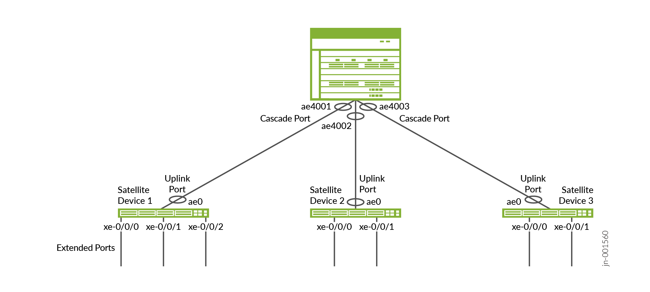
EVPN-VXLAN tunnels transport upstream traffic toward the AD, and downstream traffic toward the SD. Cascade ports and uplink ports facilitate the traffic flow between devices.
Multiple cascade and uplink ports bundled into aex are deployed between the AD and connected SDs. Bundles may also contain only a single cascade port and uplink port. Aex is required for redundancy and bandwidth assurance. NGPE utilizes high-speed ports between the AD and SDs, and low-speed ports on the SDs toward the access nodes. SDs might connect to only one AD. SD multihoming is not supported in NGPE.
Each SD is represented as a remote VXLAN tunnel endpoint (VTEP) on the AD, and each extended port is assigned a virtual network identifier (VNI). VTEP's are the points at which VXLAN tunnel traffic is either encapsulated or de-encapsulated, depending on traffic direction. The VNI is a unique, 24-bit value per L2 segment. The VNI is assigned to each extended port on a given SD, with each SD hosting multiple extended ports. Upstream traffic from an extended port is encapsulated and sent through a VXLAN tunnel to the AD. The AD de-encapsulates the data and associates it with an extended port based on the source SDs IP and VNI. Downstream traffic is handled in a similar manner.
Hardware and Software Requirements
The following table shows the hardware platforms supported for AD and SD roles. MX Series routers in the AD role must use Advanced Forwarding Toolkit (AFT) FPCs. We don't support mixing AFT FPCs and non-AFT FPCs in the same chassis when NGPE is configured.
| Supported OS Release | Supported Aggregation Devices | Supported Satellite Devices |
|---|---|---|
| Junos OS 25.4R1 | MX304 | EX4400-48P |
| EX4400-48T | ||
| QFX5120-48T | ||
| QFX5120-48Y | ||
| MX10004 with MX10K-LC4800 or MX10K-LC9600 FPCs | EX4400-48P | |
| EX4400-48T | ||
| QFX5120-48T | ||
| QFX5120-48Y | ||
| MX10008 with MX10K-LC4800 or MX10K-LC9600 FPCs | EX4400-48P | |
| EX4400-48T | ||
| QFX5120-48T | ||
| QFX5120-48Y |
JNU
The AD is solely responsible for configuring and maintaining every SD. The AD is also responsible for distributing the initial configuration and future updates to the SDs. During the initial launch and reboot, individual SDs should automatically install their respective schema into the AD.
Table 1 introduces JNU's role in NGPE. NGPE runs JNU software on the AD to manage SD configurations, and JNU is included with Junos OS. NETCONF over SSH is used across the AD to SD connection.
NGPE Fabric
NGPE configuration is contained within a logical system on the AD. The fabric, or overlay network, provides the transport mechanism used to carry traffic between ADs and SDs. NGPE requires that EVPN-VXLAN is configured in MAC-VRF routing instances. A single MAC-VRF instance is provisioned, using vlan-aware-bundle service.
NGPE requires separate logical interfaces for carrying management traffic and fabric traffic. Both logical interfaces are configured on the same aex member link. NGPE supports the coexistence of the fabric traffic and the management traffic over this single connection. Per-unit scheduling functionality avoids any resource conflicts, and default COS settings guarantee management traffic bandwidth under periods of congestion.
Each extended port on an SD hosts an L2 logical interface. Traffic is sent to the ADs VTEP and VNI corresponding to the VLAN. ADs don't use EVPN Type 2 route advertisements to learn MACs or IPs, which helps to prevent SDs from creating tunnels between each other. VXLAN tunnels will only operate between the AD and connected SDs. Disabling MAC/IP learning means the traffic moving through the extended ports is flooded across the VLAN associated with the L2 interface. The AD floods a single copy of the traffic to minimize forwarding disruption.
NGPE requires that all traffic is transparently transported between SDs and ADs. Layer 2 protocol tunneling (L2PT) must be configured on the SDs for this reason. Additionally, broadcast, unknown unicast, and multicast (BUM) traffic must not be throttled, as it must also be transparent.
Extended Ports Overview
Extended ports are customer-facing interfaces, and are created during satellite onboarding. The SD side of an extended port is an access port. The AD side is a virtual port. Extended ports are not core-facing. SDs are represented on the AD as a virtual slot, which allows extended port labeling to follow standard Junos nomenclature for interfaces. For example, an extended port on the AD would appear as xe-100/0/0, and on the SD as xe-0/0/0. Aex is supported for extended ports. Member links aren't required to reside on the same SD. All member links per aex must use the same interface speed.
EVPN Type 3 routes are used for tracking extended ports on the SD to reflect their status on the AD. Type 3 routes also track the status of available services on the extended ports.
Extended ports are created in the "Down" state. EVPN Type 3 advertisements signal the extended ports status to the AD, and the AD enables the extended port associated with the SDs VTEP and VNI. EVPN Type 3 routes also signal the AD when a working extended port stops transmitting. The AD updates the ports' status so alternate paths, if available, can be utilized. You configure extended ports on the AD.
Cascade and Uplink Ports Overview
Cascade ports and uplink ports are the physical, high-speed ports between the AD and SDs. Cascade ports on the AD side connect with uplink ports on the SD side. Multiple cascade ports and uplink ports are bundled into aex configuration to ensure bandwidth and redundancy. The user defines the ports during the initial configuration process, and then commit scripts provision the cascade and uplink ports as part of satellite onboarding, including the creation of the aex bundle.
Satellite Device Hardware
NGPE can support:
-
Up to 10 SDs per AD.
-
Each SD connects to its AD through 1 or more cascade ports.
-
Each SD hosts up to 48 ports.
NGPE Commit Script and Configuration Management
NGPE uses a commit script-based mechanism for setting up the NGPE fabric. The commit script
is triggered with the port-extender configuration statement at the
edit services hierarchy. The port extender configuration stanza contains
the fabric details and satellite connectivity information.
NGPE commit scripts are not user-configurable and should never be altered.
Configuration Management
When a commit is made at the AD, a commit check is issued to all SDs. The commit process will abort if the commit check fails. The configuration will revert to the previous state on all SDs. Conversely, if the commit check is successful, the AD sends a commit to all SDs. If the commit operation fails on any SD, the failure will be logged in the system, but the commit will still proceed successfully on the other SDs.
After a commit has been issued, the following message might appear. You can disregard it.
warning: Clear Sat change bits terminated abnormally
The AD will overwrite any existing configuration on an SD when the SD joins the NGPE network. Junos does maintain rollback versions, however you can't rollback an SD which is active in NGPE without the device being removed from the NGPE topology.
Direct configuration changes will be blocked on the SD once it has joined the AD. Only operational commands are allowed on the SD. The following example shows the error message when a user attempts to access configuration mode directly on an SD.
root@device:~# cli
root@device: > edit
error: unknown command: edit
Configuration changes cannot be made as the node is managed by a JNU controller. Please make the configuration changes from the controller.
root@device: > quit
Operational Command Management
The AD serves as the central hub for command line interface (CLI) operations across all SDs. The ADs primary functions include distributing command requests to each SD and aggregating their responses. When a command is issued, it is forwarded to the specified SD(s), and all responses are collected sequentially in the output.
The AD should also manage different schema models running on the SDs. When an SD is added, the version and model details are provided. This process allows the schema to be installed and merged during the initial synchronization between the AD and SDs. The JNU management process (JNUD) is responsible for propagating commands from the AD to the SDs.