Configuring Service Chaining Using JDM
Understanding Service Chaining on Disaggregated Junos OS Platforms
In many network environments, it is common for traffic to flow through several network services on the way to its destination. These services—firewalls, Network Address Translators (NAT), load balancers, and so on—are generally spread across multiple network elements. Each device is a separate piece of hardware, providing a different service, and requiring separate operation and management. This method of linking together multiple network functions could be thought of as physical service chaining.
A more efficient model for service chaining is to virtualize and consolidate network functions onto a single device.
Platforms running the disaggregated Junos OS software support virtualized service chaining. These devices enable virtual network functions (VNFs) by supporting the installation and instantiation of VNFs. VNFs can be linked together to provide network services for traffic flowing through the device, as shown in Figure 1.

Configuring Service Chaining Using VLANs
You can achieve service chaining using VLANs.
Ensure that connectivity to the host is not lost during the configuration process.
To configure service chaining:
Configuring Service Chaining Using DHCP Services on VLANs
Using DHCP services, you need not manually configure the IP addresses on the VNF interfaces to achieve service-chaining. Enable DHCP clients on the glue bridge interfaces within the VNF for an IP address to be assigned from the DHCP pool. Based on the IP subnet, the IRB interface on the VLAN is automatically mapped to the corresponding subnet dhcp pool.
To configure service chaining:
To check the assigned IP address, use the show system visibility vnf command.
Example: Configuring Service Chaining Using VLANs on NFX250 Network Services Platform
This example shows how to configure service chaining using VLANs on the host bridge.
Requirements
This example uses the following hardware and software components:
NFX250 running Junos OS Release 15.1X53-D45
Before you configure service chaining, be sure you have:
Installed and launched the relevant VNFs, assigned the corresponding interfaces, and configured the resources.
Overview
Service chaining on a device running the disaggregated Junos OS allows multiple services, or virtual network functions (VNFs), to be applied to traffic as it flows through the device. This example explains how to configure the various layers of the device to enable traffic to enter the device, flow through two service VNFs, and exit the device.
Topology
This example uses a single device running the disaggregated Junos OS, as shown in Figure 2.

This example is configured using the Juniper Device Manager (JDM) and Junos Control Plane (JCP). The key configuration elements include:
The Packet Forwarding Engine’s front panel ports.
The Packet Forwarding Engine’s internal-facing ports.
A routing instance named host-os. The host-os routing instance is the CLI construct that provides the ability to configure host OS elements from the JDM.
NIC ports. As these interfaces are not directly configurable, they are abstracted in the host OS. Using the JDM CLI, NIC interfaces (sxe ports) are configured in the host-os routing instance as “hsxe” interfaces.
The VM interfaces. In the JDM, VNF interfaces must use the format eth#, where # is from 2 through to 9.
VLANs, to provide bridging between the sxe and VM interfaces.
Configuration
- Configuring the Packet Forwarding Engine Interfaces
- Configuring the VNF Interfaces and Creating the Service Chain
Configuring the Packet Forwarding Engine Interfaces
CLI Quick Configuration
To quickly configure the Packet Forwarding Engine interfaces, enter the following configuration statements from the JCP:
[edit]
user@jcp#

set vlans vlan1 vlan-id 77
set interfaces ge-0/0/2.0 family ethernet-switching vlan members vlan1
set interfaces sxe-0/0/0.0 family ethernet-switching interface-mode trunk
set interfaces sxe-0/0/0.0 family ethernet-switching vlan members vlan1
set vlans vlan2 vlan-id 1177
set interfaces xe-0/0/12.0 family ethernet-switching interface-mode trunk
set interfaces xe-0/0/12.0 family ethernet-switching vlan members vlan2
set interfaces sxe-0/0/0.0 family ethernet-switching vlan members vlan2
Step-by-Step Procedure
To configure the Packet Forwarding Engine interfaces:
Connect to the JCP.
user@jdm> ssh vjunos0
user@jcp> configure
[edit]
user@jcp#
Configure a VLAN for the LAN-side interfaces.
user@jcp# set vlans vlan1 vlan-id 77
Configure the Packet Forwarding Engine’s LAN-side front panel port and add it to the LAN-side VLAN.
The LAN-side port is typically an access port, but could be a trunk port if appropriate.
user@jcp# set interfaces ge-0/0/2.0 family ethernet-switching vlan members vlan1
Configure the Packet Forwarding Engine’s LAN-side internal-facing interface as a trunk port and add it to the LAN-side VLAN.
The internal-facing interfaces are typically trunk ports, as they must support traffic from multiple front panel ports and VLANs.
user@jcp# set interfaces sxe-0/0/0.0 family ethernet-switching interface-mode trunk
user@jcp# set interfaces sxe-0/0/0.0 family ethernet-switching vlan members vlan1
Configure a VLAN for the WAN-side interfaces.
user@jcp# set vlans vlan2 vlan-id 1177
Configure the Packet Forwarding Engine’s WAN-side front panel port as a trunk port and add it to the WAN-side VLAN.
The WAN-side front panel port is typically a trunk port, as it might be required to support multiple VLANs.
user@jcp# set interfaces xe-0/0/12.0 family ethernet-switching interface-mode trunk
user@jcp# set interfaces xe-0/0/12.0 family ethernet-switching vlan members vlan2
Configure the Packet Forwarding Engine’s WAN-side internal-facing interface as a trunk port and add it to the WAN-side VLAN.
The internal-facing interfaces are typically trunk ports, as they must support traffic from multiple front panel ports and VLANs.
user@jcp# set interfaces sxe-0/0/0.0 family ethernet-switching vlan members vlan2
Commit the configuration and return to the JDM.
user@jcp# commit and-quit
user@jcp> exit
user@jdm>
Results
From configuration mode, check the results of your configuration by entering the following show commands:
[edit]
user@jcp# show interfaces ge-0/0/2
unit 0 {
    family ethernet-switching {
        vlan {
            members vlan1;
        }
    }
}

[edit]
user@jcp# show interfaces xe-0/0/12
unit 0 {
    family ethernet-switching {
        interface-mode trunk;
        vlan {
            members vlan2;
        }
    }
}

[edit]
user@jcp# show interfaces sxe-0/0/0
unit 0 {
    family ethernet-switching {
        interface-mode trunk;
        vlan {
            members [vlan1 vlan2];
        }
    }
}


[edit]
user@jcp# show vlans
vlan2 {
    vlan-id 1177;
}
vlan1 {
    vlan-id 77;
}
Configuring the VNF Interfaces and Creating the Service Chain
Step-by-Step Procedure
Once you have completed the configuration on JCP, you need to:
Configure the host-os instance with either with LAN, WAN, or glue-vlan to be used for service chaining
user@jdm# set host-os vlans vlan1 vlan-id 77
user@jdm# set host-os vlans vlan2 vlan-id 1177
user@jdm# set host-os vlans glue-vlan vlan-id 123
Bring up the VM1 with one virtio interface mapped to VLAN, and another interface mapped to glue-vlan.
user@jdm# set virtual-network-functions VM1 interfaces eth2 mapping vlan members vlan1
user@jdm# set virtual-network-functions VM1 interfaces eth3 mapping vlan members glue-vlan
Similarly bring up VM2 with one interface with one interface mapped to VLAN2, and the second interface mapped to the same glue-vlan.
user@jdm# set virtual-network-functions VM2 interfaces eth2 mapping vlan members vlan2
user@jdm# set virtual-network-functions VM2 interfaces eth3 mapping vlan members glue-vlan
Finally, configure the IP addresses and static routes for each interface of the VMs as shown in Figure 2.
Example: Configuring Service Chaining Using SR-IOV on NFX250 Network Services Platform
This example shows how to configure service chaining using SR-IOV on platforms running the disaggregated Junos OS software.
Requirements
This example uses the following hardware and software components:
NFX250 running Junos OS Release 15.1X53-D45
Before you configure service chaining, be sure you have:
Installed and launched the relevant VNFs
Overview
Service chaining on a device running the disaggregated Junos OS allows multiple services, or virtual network functions (VNFs), to be applied to traffic as it flows through the device. This example explains how to configure the various layers of the device to enable traffic to enter the device, flow through two service VNFs, and exit the device.
Topology
This example uses a single device running the disaggregated Junos OS, as shown in Figure 3.
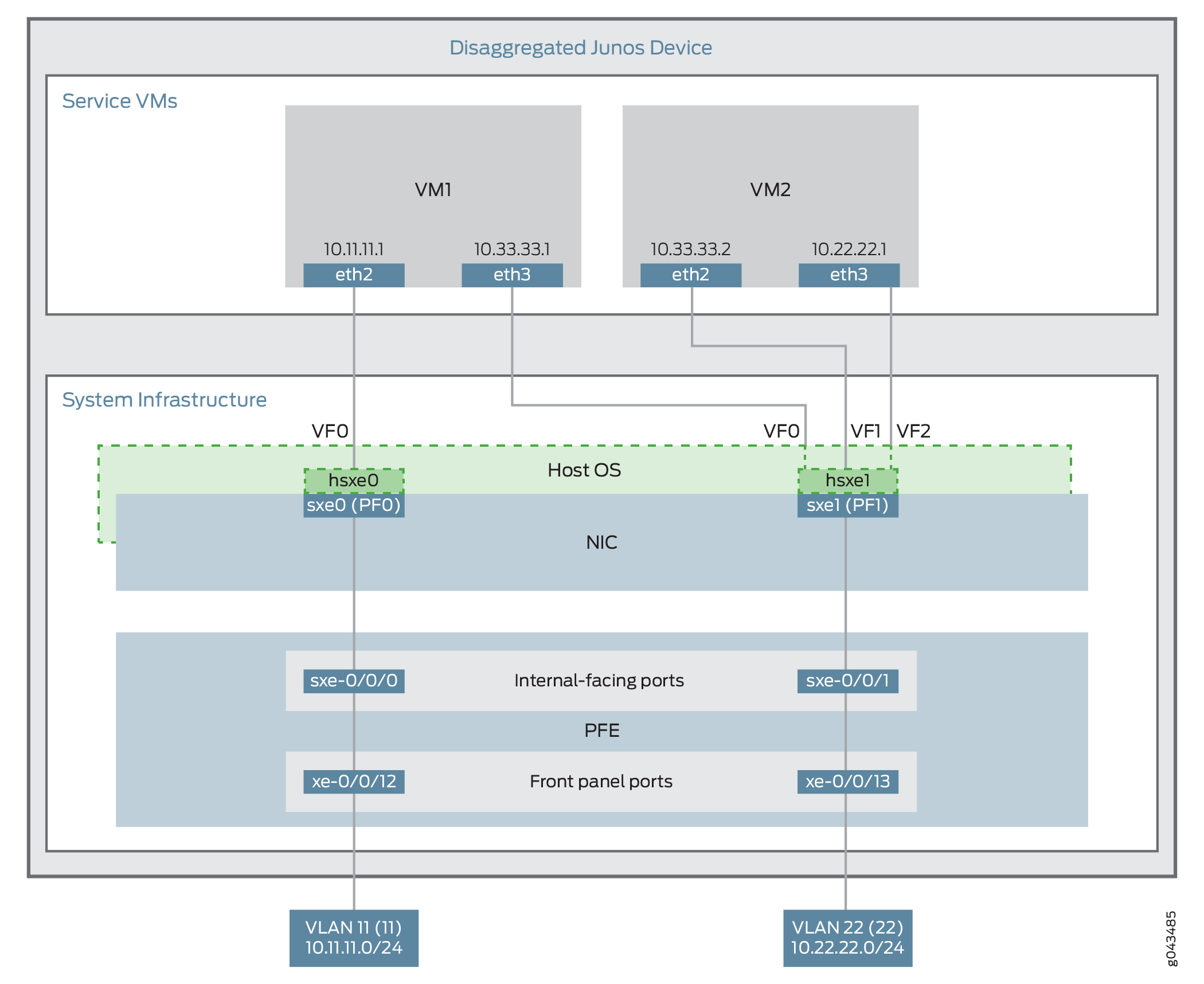
This example uses the Packet Forwarding Engine’s front panel ports xe-0/0/12 and xe-0/0/13, and its internal-facing ports, sxe-0/0/0 and sxe-0/0/1. The internal NIC’s two ports (sxe0 and sxe1) are not configured directly; instead, they are abstracted at the host OS layer and configured as interfaces hsxe0 and hsxe1. The VMs use two interfaces each (eth2 and eth3).
These elements are generally separated into two parts: a LAN side and a WAN side.
As this example uses SR-IOV, the NIC ports’ virtual functions (VFs) are used to bypass the host OS and provide direct NIC-to-VM connectivity. Given this setup, it might seem unusual to see host OS interfaces (hsxe0 and hsxe1) included in this scenario. However, as there is no direct configuration method for the NIC ports, it is necessary to use their abstracted versions, hsxe0 and hsxe1.
This example is configured using the Juniper Device Manager (JDM) and Junos Control Plane (JCP). The key configuration elements include:
The Packet Forwarding Engine’s front panel ports.
The Packet Forwarding Engine’s internal-facing ports.
NIC ports. Because NIC interfaces (sxe ports) cannot be configured directly, the host OS construct for these interfaces (hsxe) must be used.
The VNF interfaces. In the JDM, VNF interfaces must use the format eth#, where # is from 2 through to 9.
The virtual function setting, to indicate SR-IOV is being used to provide direct access between hsxe and VNF interfaces.
Configuration
This example describes:
Configuring the Packet Forwarding Engine Interfaces
CLI Quick Configuration
To quickly configure the Packet Forwarding Engine interfaces, enter the following configuration statements from the JCP:
[edit]
user@jcp#

set vlans Vlan11 vlan-id 11
set interfaces xe-0/0/12.0 family ethernet-switching vlan member Vlan11
set interfaces sxe-0/0/0.0 family ethernet-switching interface-mode trunk
set interfaces sxe-0/0/0.0 family ethernet-switching vlan member Vlan11
set vlans Vlan22 vlan-id 22
set interfaces xe-0/0/13.0 family ethernet-switching interface-mode trunk
set interfaces xe-0/0/13.0 family ethernet-switching vlan member Vlan22
set interfaces sxe-0/0/1.0 family ethernet-switching interface-mode trunk
set interfaces sxe-0/0/1.0 family ethernet-switching vlan member Vlan22
Step-by-Step Procedure
To configure the Packet Forwarding Engine interfaces:
Connect to the JCP.
user@jdm> ssh vjunos0
user@jcp> configure
[edit]
user@jcp#
Configure a VLAN for the LAN-side interfaces.
user@jcp# set vlans Vlan11 vlan-id 11
Configure the Packet Forwarding Engine’s LAN-side front panel port, and add it to the LAN-side VLAN.
The LAN-side port is typically an access port, but could be a trunk port if appropriate.
user@jcp# set interfaces xe-0/0/12.0 family ethernet-switching vlan members Vlan11
Configure the Packet Forwarding Engine’s LAN-side internal-facing interface as a trunk port, and add it to the LAN-side VLAN.
The internal-facing interfaces are typically trunk ports, as they must support traffic from multiple front panel ports and VLANs.
user@jcp# set interfaces sxe-0/0/0.0 family ethernet-switching interface-mode trunk
user@jcp# set interfaces sxe-0/0/0.0 family ethernet-switching vlan member Vlan11
Configure a VLAN for the WAN-side interfaces.
user@jcp# set vlans Vlan22 vlan-id 22
Configure the Packet Forwarding Engine’s WAN-side front panel port as a trunk port, and add it to the WAN-side VLAN.
The WAN-side front panel port is typically a trunk port, as it might be required to support multiple VLANs.
user@jcp# user@jcp# set interfaces xe-0/0/13.0 family ethernet-switching interface-mode trunk
user@jcp# user@jcp# set interfaces xe-0/0/13.0 family ethernet-switching vlan members Vlan22
Configure the Packet Forwarding Engine’s WAN-side internal-facing interface as a trunk port, and add it to the WAN-side VLAN.
The internal-facing interfaces are typically trunk ports, as they must support traffic from multiple front panel ports and VLANs.
user@jcp# set interfaces sxe-0/0/1.0 family ethernet-switching interface-mode trunk
user@jcp# set interfaces sxe-0/0/1.0 family ethernet-switching vlan members Vlan22
Commit the configuration and return to the JDM.
user@jcp# commit and-quit
user@jcp> exit
user@jdm>
Results
From configuration mode, check the results of your configuration by entering the following show commands:
[edit]
user@jcp# show interfaces xe-0/0/12
unit 0 {
    family ethernet-switching {
        vlan {
            members Vlan11;
        }
    }
}

[edit]
user@jcp# show interfaces xe-0/0/13
unit 0 {
    family ethernet-switching {
        interface-mode trunk;
        vlan {
            members Vlan22;
        }
    }
}

[edit]
user@jcp# show interfaces sxe-0/0/0
unit 0 {
    family ethernet-switching {
        interface-mode trunk;
        vlan {
            members Vlan11;
        }
    }
}

[edit]
user@jcp# show interfaces sxe-0/0/1
unit 0 {
    family ethernet-switching {
        interface-mode trunk;
        vlan {
            members Vlan22;
        }
    }
}

[edit]
user@jcp# show vlans
Vlan11 {
    vlan-id 11;
}
Vlan22 {
    vlan-id 22;
}
Creating the Service Chain
Step-by-Step Procedure
To configure the VNF interfaces and create the service chain:
Configure VM1’s LAN-side interface as a Layer 3 interface, and map it to the LAN-side NIC interface. Include the virtual function (VF) setting to specify direct NIC-to-VM connectivity. VNF must use the interfaces from eth2 through to eth9.
The hsxe interface is the configurable representation of the related NIC (sxe) interface.
user@jdm> configure
[edit]
user@jdm# set virtual-network-functions vnf1 interfaces eth2 mapping hsxe0 virtual-function
Configure VM1’s WAN-side interface from sxe1 NIC as shown in Figure 3.
user@jdm# set virtual-network-functions vnf1 interfaces eth3 mapping hsxe1 virtual-function
Similarly bring up VM2 with both interfaces eth2 and eth3 on sxe1 NIC.
user@jdm# set virtual-network-functions vnf2 interfaces eth2 mapping hsxe1 virtual-function
user@jdm# set virtual-network-functions vnf2 interfaces eth3 mapping hsxe1 virtual-function
Finally, configure the IP addresses and static routes for each interface of the VNFs, and add routes to achieve the complete bidirectional path for the service chain.