Chassis Cluster on NFX150 Devices
A chassis cluster, where two devices operate as a single device, provides high availability on NFX150 devices. Chassis clustering involves the synchronizing of configuration files and the dynamic runtime session states between the devices, which are part of the chassis cluster setup.
NFX150 Chassis Cluster Overview
You can configure NFX150 devices to operate in cluster mode by connecting and configuring a pair of devices to operate like a single node, providing redundancy at the device, interface, and service level.
When two devices are configured to operate as a chassis cluster, each device becomes a node of that cluster. The two nodes back up each other, with one node acting as the primary device and the other node acting as the secondary device, ensuring stateful failover of processes and services when the system or hardware fails. If the primary device fails, the secondary device takes over the processing of traffic.
The nodes of a cluster are connected together through two links called control link and fabric link. The devices in a chassis cluster synchronize the configuration, kernel, and PFE session states across the cluster to facilitate high availability, failover of stateful services, and load balancing.
Control link—Synchronizes the configuration between the nodes. When you submit configuration statements to the cluster, the configuration is automatically synchronized over the control interface.
To create a control link in a chassis cluster, connect the heth-0-0 port on one node to the heth-0-0 port on the second node.
Note:You can use only the heth-0-0 port to create a control link.
Fabric link (data link)—Forwards traffic between the nodes. Traffic arriving on a node that needs to be processed on the other node is forwarded over the fabric link. Similarly, traffic processed on a node that needs to exit through an interface on the other node is forwarded over the fabric link.
You can use any port except the heth-0-0 to create a fabric link.
Chassis Cluster Modes
The chassis cluster can be configured in active/passive or active/active mode.
Active/passive mode—In active/passive mode, the transit traffic passes through the primary node while the backup node is used only in the event of a failure. When a failure occurs, the backup device becomes the primary device and takes over all forwarding tasks.
Active/active mode—In active/active mode, the transit traffic passes through both nodes all the time.
Chassis Cluster Interfaces
The chassis cluster interfaces include:
Redundant Ethernet (reth) interface—A pseudo-interface that includes a physical interface from each node of a cluster. The reth interface of the active node is responsible for passing the traffic in a chassis cluster setup.
A reth interface must contain, at minimum a pair of Gigabit Ethernet interfaces that are referred to as child interfaces of the redundant Ethernet interface (the redundant parent). If two or more child interfaces from each node are assigned to the redundant Ethernet interface, a redundant Ethernet interface link aggregation group can be formed.
Note:You can configure a maximum of 128 reth interfaces on NFX150 devices.
Control interface—An interface that provides the control link between the two nodes in the cluster. This interface is used for routing updates and for control plane signal traffic, such as heartbeat and threshold information that trigger node failover.
Note:By default, the heth-0-0 port is configured as the dedicated control interface on NFX150 devices. Therefore, you cannot map the heth-0-0 port to any other virtual interface if the device is part of a chassis cluster.
Fabric interface—An interface that provides the physical connection between two nodes of a cluster. A fabric interface is formed by connecting a pair of Ethernet interfaces back-to-back (one from each node). The Packet Forwarding Engines of the cluster uses this interface to transmit transit traffic and to synchronize the runtime state of the data plane software. You must specify the physical interfaces to be used for the fabric interface in the configuration.
Chassis Cluster Limitation
Redundant LAG (RLAG) of reth member interfaces of the same node is not supported. A reth interface with more than one child interface per node is called RLAG.
Example: Configuring a Chassis Cluster on NFX150 Devices
This example shows how to set up chassis clustering on NFX150 devices.
Requirements
Before you begin:
Physically connect the two devices and ensure that they are the same NFX150 model.
Ensure that both devices are running the same Junos OS version
Remove all interface mapping for the control port heth-0-0 on both the nodes.
Connect the dedicated control port heth-0-0 on node 0 to the heth-0-0 port on node 1.
Connect the fabric port on node 0 to the fabric port on node 1.
Overview
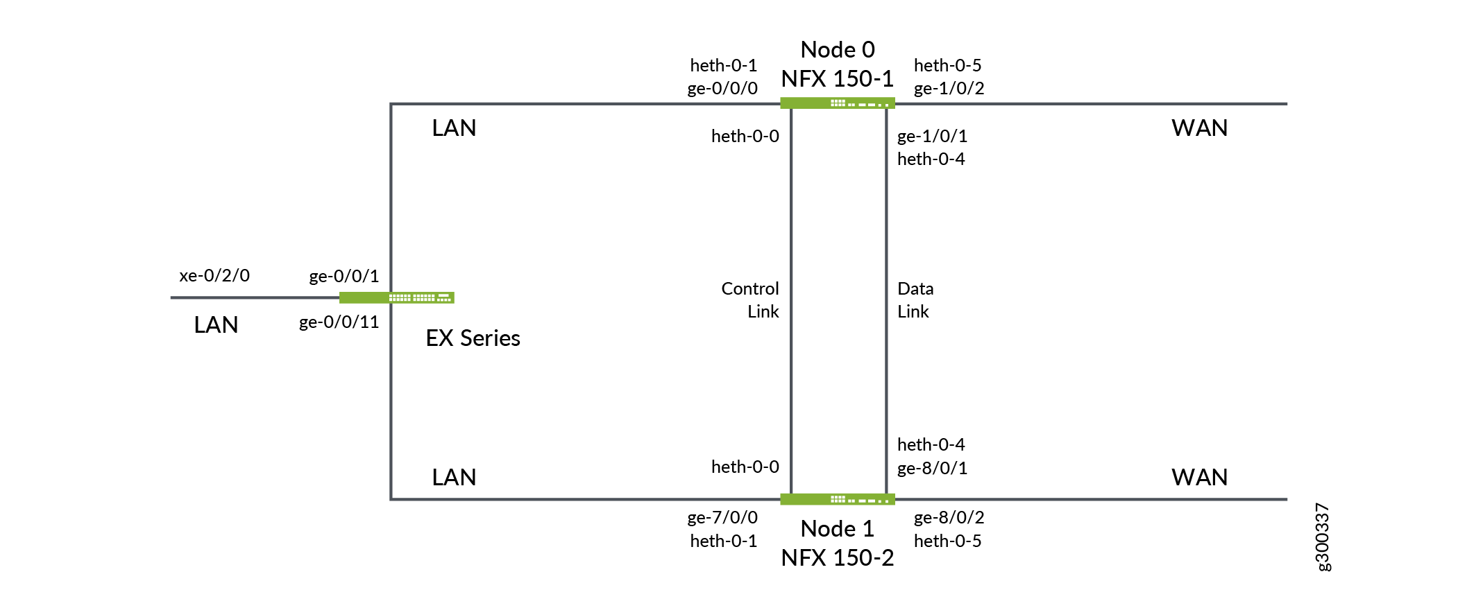
Figure 1 shows the topology used in this example. This example shows how to set up basic active/passive chassis clustering. One device actively maintains control of the chassis cluster. The other device passively maintains its state for cluster failover capabilities in case the active device becomes inactive.
This example does not describe in detail miscellaneous configurations such as how to configure security features. They are essentially the same as they would be for standalone configurations.
Configuration
Configuring a Chassis Cluster
Step-by-Step Procedure
Configure the cluster ID on both the nodes and reboot the devices. A reboot is required to enter into cluster mode after the cluster ID and node ID are set.
Note:You must enter the operational mode to issue the commands on both devices.
user@host1> set chassis cluster cluster-id 1 node 0 reboot
user@host2> set chassis cluster cluster-id 1 node 1 reboot
The cluster-id is the same on both devices, but the node ID must be different because one device is node 0 and the other device is node 1. The range for the cluster-id is 0 through 255 and setting it to 0 is equivalent to disabling cluster mode.
Verify that the chassis cluster is configured successfully:
user@host1> show chassis cluster status Monitor Failure codes: CS Cold Sync monitoring FL Fabric Connection monitoring GR GRES monitoring HW Hardware monitoring IF Interface monitoring IP IP monitoring LB Loopback monitoring MB Mbuf monitoring NH Nexthop monitoring NP NPC monitoring SP SPU monitoring SM Schedule monitoring CF Config Sync monitoring RE Relinquish monitoring Cluster ID: 1 Node Priority Status Preempt Manual Monitor-failures Redundancy group: 0 , Failover count: 0 node0 1 primary no no None node1 1 secondary no no Noneroot@NFX150-1> show chassis cluster information node0: -------------------------------------------------------------------------- Redundancy Group Information: Redundancy Group 0 , Current State: primary, Weight: 255 Time From To Reason Mar 15 11:33:47 hold secondary Hold timer expired Mar 15 11:34:03 secondary primary Only node present Chassis cluster LED information: Current LED color: Green Last LED change reason: No failures node1: -------------------------------------------------------------------------- Redundancy Group Information: Redundancy Group 0 , Current State: secondary, Weight: 255 Time From To Reason Mar 15 12:14:49 hold secondary Hold timer expired Chassis cluster LED information: Current LED color: Green Last LED change reason: No failures
After the chassis cluster is set up, you can enter the configuration mode and perform all the configurations on the primary node, node0.
Configure the host names and the out-of-band management IP addresses for nodes 0 and 1:
user@host1# set groups node0 system host-name NFX150-1
user@host1# set groups node0 interfaces fxp0 unit 0 family inet address 10.204.41.80/20
user@host1# set groups node1 system host-name NFX150-2
user@host1# set groups node1 interfaces fxp0 unit 0 family inet address 10.204.41.90/20
If you are accessing the device from a different subnet other than the one configured for the out-of-band management, then set up a static route
user@host1# set groups node0 routing-options static route 0.0.0.0/0 next-hop 10.204.47.254
user@host1# set groups node1 routing-options static route 0.0.0.0/0 next-hop 10.204.47.254
Map the physical LAN port to the virtual LAN interface on FPC0:
user@host1# set groups node0 vmhost virtualization-options interfaces ge-0/0/0 mapping interface heth-0-1
user@host1# set groups node1 vmhost virtualization-options interfaces ge-7/0/0 mapping interface heth-0-1
Note:In a chassis cluster, the FPC1 ports on the secondary node are denoted as ge-8/0/x, and the FPC0 ports are denoted as ge-7/0/x.
Map the physical WAN port to the virtual WAN interface on FPC1:
user@host1# set groups node0 vmhost virtualization-options interfaces ge-1/0/2 mapping interface heth-0-5
user@host1# set groups node1 vmhost virtualization-options interfaces ge-8/0/2 mapping interface heth-0-5
Configure port peering between the FPC0 and FPC1 on nodes 0 and 1. Port peering ensures that when a LAN interface controlled by the Layer 2 dataplane (FPC0) fails, the corresponding interface on the Layer 3 dataplane (FPC1) is marked down and vice versa. This helps in the failover of the corresponding redundant group to the secondary node.
user@host# set groups node0 chassis cluster redundant-interface ge-1/0/0 mapping-interface ge-0/0/0
user@host# set groups node1 chassis cluster redundant-interface ge-8/0/0 mapping-interface ge-7/0/0
Configure the fabric ports:
user@host1# set groups node0 vmhost virtualization-options interfaces ge-1/0/1 mapping interface heth-0-4
user@host1# set groups node1 vmhost virtualization-options interfaces ge-8/0/1 mapping interface heth-0-4
user@host1# set interfaces fab0 fabric-options member-interfaces ge-1/0/1
user@host1# set interfaces fab1 fabric-options member-interfaces ge-8/0/1
Apply the node-specific configurations on nodes 0 and 1:
user@host1# set apply-groups "${node}"Enable the system to perform control link recovery automatically. After it determines that the control link is healthy, the system issues an automatic reboot on the node that was disabled when the control link failed. When the disabled node reboots, it rejoins the cluster
user@host1# set chassis cluster control-link-recovery
Verify the interfaces:
user@host1# run show chassis cluster interfaces
Configuring Redundant Groups and Redundant Interfaces
Step-by-Step Procedure
-
Configure redundancy groups 1 and 2. Both
redundancy-group 1andredundancy-group 2control the data plane and include the data plane ports. Each node has interfaces in a redundancy group. As part of redundancy group configuration, you must also define the priority for control plane and data plane—which device is preferred for the control plane, and which device is preferred for the data plane. For chassis clustering, higher priority is preferred. The higher number takes precedence.In this configuration,
node 0is the active node as it is associated withredundancy-group 1. reth0 is member ofredundancy-group 1and reth1 is member ofredundancy-group 2. You must configure all changes in the cluster through node 0. If node 0 fails, then node 1 will be the active node.user@host1# set chassis cluster redundancy-group 1 node 0 priority 100 user@host1# set chassis cluster redundancy-group 1 node 1 priority 100 user@host1# set chassis cluster redundancy-group 2 node 0 priority 100 user@host1# set chassis cluster redundancy-group 2 node 1 priority 100
-
Enable preempt for
redundancy-group 1.user@host1# set chassis cluster redundancy-group 1 preempt
Note:If preempt is added to a redundancy group configuration, the device with the higher priority in the group can initiate a failover to become the primary device. By default, preemption is disabled.
Configure the interfaces that the redundancy groups need to monitor to determine whether an interface is up or down.
By default, redundancy groups have a threshold tolerance value of 255. When an interface monitored by a redundancy group becomes unavailable, its weight is subtracted from the redundancy group's threshold. When a redundancy group's threshold reaches 0, it fails over to the other node.
user@host# set chassis cluster redundancy-group 1 interface-monitor ge-1/0/0 weight 255
user@host# set chassis cluster redundancy-group 1 interface-monitor ge-8/0/0 weight 255
user@host# set chassis cluster redundancy-group 2 interface-monitor ge-1/0/2 weight 255
user@host# set chassis cluster redundancy-group 2 interface-monitor ge-8/0/2 weight 255
Configure the data interfaces so that in the event of a data plane failover, the other chassis cluster member can take over the connection seamlessly.
Define the following parameters:
The maximum number of reth interfaces for the cluster, so that the system can allocate the appropriate resources for them.
user@host1# set chassis cluster reth-count 5
The heartbeat interval and threshold, which define the wait time before failover is triggered in the chassis cluster.
user@host1# set chassis cluster heartbeat-interval 1000
user@host1# set chassis cluster heartbeat-threshold 5
Membership information of the member interfaces to reth interfaces.
user@host# set interfaces ge-1/0/0 gigether-options redundant-parent reth1
user@host# set interfaces ge-1/0/2 gigether-options redundant-parent reth2
user@host# set interfaces ge-8/0/0 gigether-options redundant-parent reth1
user@host# set interfaces ge-8/0/2 gigether-options redundant-parent reth2
Configure the reth interfaces:
Configure reth1:
user@host1# set interfaces reth1 vlan-tagging user@host1# set interfaces reth1 redundant-ether-options redundancy-group 1 user@host1# set interfaces reth1 unit 0 vlan-id 100 user@host1# set interfaces reth1 unit 0 family inet address 192.0.3.1/24 user@host1# set interfaces reth1 unit 0 family inet6 address 2001:db8:1:1::/64
Configure reth2:
user@host1# set interfaces reth2 vlan-tagging user@host1# set interfaces reth2 redundant-ether-options redundancy-group 2 user@host1# set interfaces reth2 unit 0 vlan-id 200 user@host1# set interfaces reth2 unit 0 family inet address • 203.0.113.1/24 user@host1# set interfaces reth2 unit 0 family inet6 address 2001:db8:2:1::/64
Configure security policies to allow traffic from LAN to WAN, and from WAN to LAN:
user@host1# set security policies default-policy permit-all
user@host1# set security zones security-zone trust host-inbound-traffic system-services all
user@host1# set security zones security-zone trust host-inbound-traffic protocols all
user@host1# set security zones security-zone trust interfaces all
Verification
Verifying Chassis Cluster Status
Purpose
Verify the status of the chassis cluster and its interfaces.
Action
From operational mode, issue the following commands:
Verify the status of the cluster:
root@NFX150-1> show chassis cluster status
Monitor Failure codes:
    CS  Cold Sync monitoring        FL  Fabric Connection monitoring
    GR  GRES monitoring             HW  Hardware monitoring
    IF  Interface monitoring        IP  IP monitoring
    LB  Loopback monitoring         MB  Mbuf monitoring
    NH  Nexthop monitoring          NP  NPC monitoring
    SP  SPU monitoring              SM  Schedule monitoring
    CF  Config Sync monitoring      RE  Relinquish monitoring

Cluster ID: 1
Node   Priority Status               Preempt Manual   Monitor-failures

Redundancy group: 0 , Failover count: 0
node0  1        primary              no      no       None
node1  1        secondary            no      no       None

Redundancy group: 1 , Failover count: 0
node0  100      primary              yes     no       None
node1  100      secondary            yes     no       None

Redundancy group: 2 , Failover count: 0
node0  100      primary              no      no       None
node1  100      secondary            no      no       None
Verify the status of the redundancy groups:
root@NFX150-1> show chassis cluster information
node0:
--------------------------------------------------------------------------
Redundancy Group Information:

    Redundancy Group 0 , Current State: primary, Weight: 255

        Time            From                 To                   Reason
        Mar 21 12:06:18 hold                 secondary            Hold timer expired
        Mar 21 12:18:46 secondary            primary              Remote node reboot

    Redundancy Group 1 , Current State: primary, Weight: 255

        Time            From                 To                   Reason
        Mar 21 12:06:19 hold                 secondary            Hold timer expired
        Mar 21 12:08:51 secondary            primary              Remote is in secondary hold

    Redundancy Group 2 , Current State: primary, Weight: 255

        Time            From                 To                   Reason
        Mar 21 12:06:19 hold                 secondary            Hold timer expired
        Mar 21 12:18:46 secondary            primary              Remote node reboot

Chassis cluster LED information:
    Current LED color: Green
    Last LED change reason: No failures

node1:
--------------------------------------------------------------------------
Redundancy Group Information:

    Redundancy Group 0 , Current State: secondary, Weight: 255

        Time            From                 To                   Reason
        Mar 21 13:02:05 hold                 secondary            Hold timer expired

    Redundancy Group 1 , Current State: secondary, Weight: 255

        Time            From                 To                   Reason
        Mar 21 13:02:05 hold                 secondary            Hold timer expired

    Redundancy Group 2 , Current State: secondary, Weight: 255

        Time            From                 To                   Reason
        Mar 21 13:02:06 hold                 secondary            Hold timer expired

Chassis cluster LED information:
    Current LED color: Green
    Last LED change reason: No failures
Verify the status of the interfaces:
root@NFX150-1> show chassis cluster interfaces
Control link status: Up

Control interfaces:
    Index   Interface   Monitored-Status   Internal-SA   Security
    0       em1         Up                 Disabled      Disabled

Fabric link status: Up

Fabric interfaces:
    Name    Child-interface    Status                    Security
                               (Physical/Monitored)
    fab0    ge-1/0/1           Up   / Up                 Disabled
    fab0
    fab1    ge-8/0/1           Up   / Up                 Disabled
    fab1

Redundant-ethernet Information:
    Name         Status      Redundancy-group
    reth0        Down        Not configured
    reth1        Down        1
    reth2        Down        2
    reth3        Down        Not configured
    reth4        Down        Not configured

Redundant-pseudo-interface Information:
    Name         Status      Redundancy-group
    lo0          Up          0

Interface Monitoring:
    Interface         Weight    Status                    Redundancy-group
                                (Physical/Monitored)
    ge-8/0/0          255       Up  /  Up                 1
    ge-1/0/0          255       Up  /  Up                 1
    ge-8/0/2          255       Up  /  Up                 2
    ge-1/0/2          255       Up  /  Up                 2
Verify the status of the port-peering interfaces:
root@NFX150-1> show chassis cluster port-peering
node0:
--------------------------------------------------------------------------

Port peering interfaces:
    Backend L3                Mapped Peer L2
    Interface  Status         Interface  Status
    ge-1/0/0    Up            ge-0/0/0   Up

node1:
--------------------------------------------------------------------------

Port peering interfaces:
    Backend L3                Mapped Peer L2
    Interface  Status         Interface  Status
    ge-8/0/0    Up            ge-7/0/0   Up