ON THIS PAGE
Example: Configuring Service Chaining for LAN-WAN Routing
This example shows how to configure service chaining for LAN-WAN routing.
Requirements
This example uses the following hardware and software components:
NFX150 running Junos OS Release 18.1R1
Overview
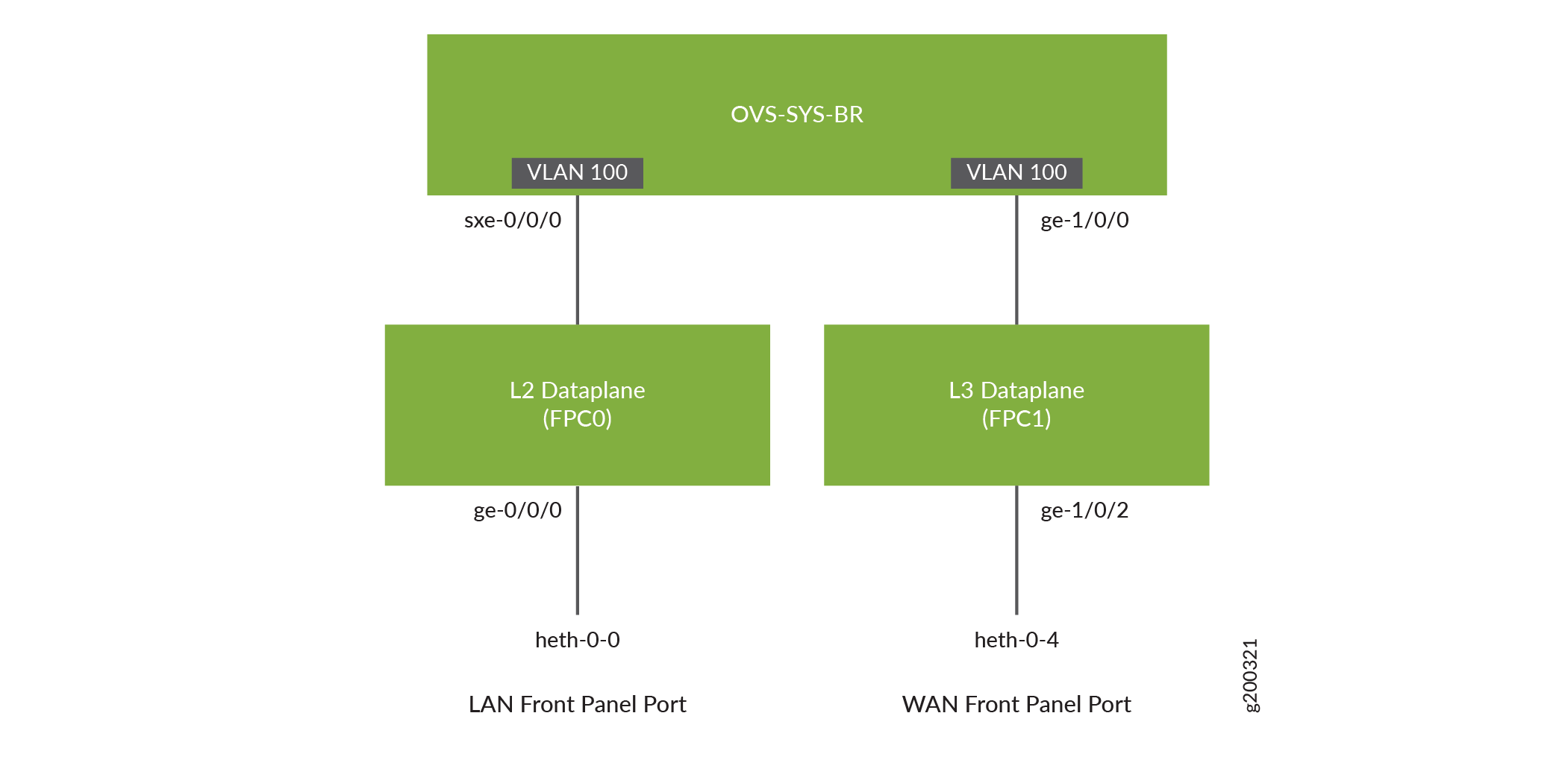
This example explains how to configure the various layers of the device to enable traffic from the LAN network to enter the device, flow through the OVS, exit the device, and enter the WAN network.
Topology
This example uses the topology shown in Figure 1.
Configuration
Map the Interfaces
Step-by-Step Procedure
Map the heth-0-0 physical port to the FPC0 interface.
user@host# set vmhost virtualization-options interfaces ge-0/0/0 mapping interface heth-0-0
Map the FPC1 interface ge-1/0/2 to the physical port heth-0-4.
user@host# set vmhost virtualization-options interfaces ge-1/0/2 mapping interface heth-0-4
Configure the Layer 2 Datapath
Step-by-Step Procedure
Configure VLANs for the LAN-side interfaces.
user@host# set vlans vlan100 vlan-id 100
Configure the LAN-side front panel ports and add them to the LAN-side VLAN.
user@host# set interfaces ge-0/0/0 unit 0 family ethernet-switching interface-mode trunk
user@host# set interfaces ge-0/0/0 unit 0 family ethernet-switching vlan members vlan100
Configure the internal-facing interfaces as trunk ports and add them to the LAN-side VLAN. The internal-facing interfaces are typically trunk ports, as they must support traffic from multiple front panel ports and VLANs.
user@host# set interfaces sxe-0/0/0 unit 0 family ethernet-switching interface-mode trunk
user@host# set interfaces sxe-0/0/0 unit 0 family ethernet-switching vlan members vlan100
Configure the Layer 3 Datapath
Step-by-Step Procedure
Configure VLAN tagging on ge-1/0/0:
user@host# set interfaces ge-1/0/0 vlan-tagging
user@host# set interfaces ge-1/0/0 unit 0 vlan-id 100
user@host# set interfaces ge-1/0/0 unit 0 family inet address 192.0.3.1/24
Configure VLAN tagging on ge-1/0/2:
user@host# set interfaces ge-1/0/2 vlan-tagging
user@host# set interfaces ge-1/0/2 unit 0 vlan-id 200
user@host# set interfaces ge-1/0/2 unit 0 family inet address 203.0.113.2/30
Verification
Verifying the Status of the Interfaces
Purpose
Verify the status of the Layer 2 and Layer 3 interfaces.
Action
To verify the status of the interfaces:
Verify the status of the physical ports.
user@host> show interfaces heth-0-0 statistics
Physical interface: heth-0-0, Enabled, Physical link is Up
  Link-level type: Ethernet, Media type: Copper, MTU: 9192, Speed: 1Gbps, Duplex: Full-duplex, Auto-negotiation: Enabled
  Device flags   : Present Running
  Current address: 00:00:5e:00:53:8d, Hardware address: 00:00:5e:00:53:8d
    Input packets : 272469
    Output packets: 674
  MAC statistics:
    Input bytes: 17438016, Input packets: 272469, Output bytes: 48658, Output packets: 674
  VF statistics:
    VF Number: 0, PCI Address: 0000:02:10:1, Mapped to: ge-0/0/0
      Input bytes: 17433984, Input packets: 272406, Output bytes: 48658, Output packets: 674, Multicast packets: 272406
    VF Number: 1, PCI Address: 0000:02:10:5, Mapped to: ge-0/0/0
      Input bytes: 0, Input packets: 0, Output bytes: 0, Output packets: 0, Multicast packets: 0
    VF Number: 2, PCI Address: 0000:02:11:1, Mapped to: ge-0/0/0
      Input bytes: 0, Input packets: 0, Output bytes: 0, Output packets: 0, Multicast packets: 0
    VF Number: 3, PCI Address: 0000:02:11:5, Mapped to: ge-0/0/0
      Input bytes: 0, Input packets: 0, Output bytes: 0, Output packets: 0, Multicast packets: 0
Verify the status of the Layer 2 (ge-0/0/x) and Layer 3 (ge-1/0/x) interfaces.
user@host > show interfaces interface-name statistics
For example:
user@host > show interfaces ge-0/0/0 statistics
Physical interface: ge-0/0/0, Enabled, Physical link is Up
  Interface index: 144, SNMP ifIndex: 518
  Link-level type: Ethernet, MTU: 9192, LAN-PHY mode, Speed: 1000mbps,
  BPDU Error: None, Loop Detect PDU Error: None, Ethernet-Switching Error: None,
  MAC-REWRITE Error: None, Loopback: Disabled, Source filtering: Disabled,
  Flow control: Enabled
  Device flags   : Present Running
  Interface flags: SNMP-Traps Internal: 0x4000
  Link flags     : None
  CoS queues     : 8 supported, 8 maximum usable queues
  Current address: 00:00:5e:00:53:43, Hardware address: 00:00:5e:00:53:43
  Last flapped   : 2018-04-18 05:38:22 UTC (2d 10:07 ago)
  Statistics last cleared: Never
  Input rate     : 0 bps (0 pps)
  Output rate    : 0 bps (0 pps)
  Input errors: 0, Output errors: 0
  Active alarms  : None
  Active defects : None
  PCS statistics                      Seconds
    Bit errors                             0
    Errored blocks                         0
  Ethernet FEC statistics              Errors
    FEC Corrected Errors                    0
    FEC Uncorrected Errors                  0
    FEC Corrected Errors Rate               0
    FEC Uncorrected Errors Rate             0
  PRBS Statistics : Disabled
  Interface transmit statistics: Disabled

  Logical interface ge-0/0/0.0 (Index 333) (SNMP ifIndex 524)
    Flags: Up SNMP-Traps 0x24024000 Encapsulation: Ethernet-Bridge
    Input packets : 147888
    Output packets: 22
    Protocol eth-switch, MTU: 9192
      Flags: Is-Primary