Configuring Ethernet OAM Link Fault Management
The Ethernet interfaces on SRX Series Firewalls support the IEEE 802.3ah standard for Operation, Administration, and Maintenance (OAM). The standard defines OAM link fault management (LFM). The below topics discuss the overview of Ethernet OAM LFM for SRX Series Firewalls, and examples of configuring OAM.
Understanding Ethernet OAM Link Fault Management for SRX Series Firewalls
Starting in Junos OS Release 15.1X49-D70, Ethernet OAM link fault management for SRX Series Firewalls is supported on SRX300, SRX320, SRX340, SRX345, SRX550M, and SRX1500 devices.
The Ethernet interfaces on SRX Series Firewalls support the IEEE 802.3ah standard for Operation, Administration, and Maintenance (OAM). The standard defines OAM link fault management (LFM). You can configure IEEE 802.3ah OAM LFM on point-to-point Ethernet links that are connected either directly or through Ethernet repeaters. The IEEE 802.3ah standard meets the requirement for OAM capabilities as Ethernet moves from being solely an enterprise technology to a WAN and access technology, and the standard remains backward-compatible with existing Ethernet technology.
The following OAM LFM features are supported:
Discovery and link monitoring—The discovery process is triggered automatically when OAM is enabled on the interface. The discovery process permits Ethernet interfaces to discover and monitor the peer on the link if it also supports the IEEE 802.3ah standard. In active mode, the interface discovers and monitors the peer on the link if the peer also supports IEEE 802.3ah OAM functionality. In passive mode, the peer initiates the discovery process. After the discovery process has been initiated, both sides participate in discovery. The device performs link monitoring by sending periodic OAM protocol data units (PDUs) to advertise OAM mode, configuration, and capabilities.
You can specify the number of OAM PDUs that an interface can miss before the link between peers is considered down.
Remote fault detection—Remote fault detection uses flags and events. Flags convey Link Fault (a loss of signal), Dying Gasp (an unrecoverable condition such as a power failure), and Critical Event (an unspecified vendor-specific critical event). You can specify the periodic OAM PDU sending interval for fault detection. SRX Series Firewalls use the Event Notification OAM PDU to notify the remote OAM device when a problem is detected. You can specify the action to be taken by the system when the configured link-fault event occurs.
Remote loopback—Remote loopback mode ensures link quality between the device and a remote peer during installation or troubleshooting. In this mode, when the interface receives a frame that is not an OAM PDU or a pause frame, it sends it back on the same interface on which it was received. The link appears to be in the active state. You can use the returned loopback acknowledgement to test delay, jitter, and throughput.
Junos OS can place a remote data terminal equipment (DTE) into loopback mode (if remote loopback mode is supported by the remote DTE). When you place a remote DTE into loopback mode, the interface receives the remote loopback request and puts the interface into remote loopback mode. When the interface is in remote loopback mode, all frames except OAM PDUs are looped back without any changes made to the frames. OAM PDUs continue to be sent and processed.
Table 1 lists the interfaces modes supported.
Interfaces |
Mode |
|---|---|
Physical interface (fe/ge) |
Family
|
IFD encapsulations
|
|
Aggregated Ethernet interface (Static or LACP lag) |
Family
|
IFD encapsulations
|
Example: Configuring Ethernet OAM Link Fault Management on a Security Device
Starting in Junos OS Release 15.1X49-D70, configuring Ethernet OAM link fault management is supported on SRX300, SRX320, SRX340, SRX345, SRX550M, and SRX1500 devices.
The Ethernet interfaces on the SRX Series Firewalls support the IEEE 802.3ah standard for Operation, Administration, and Maintenance (OAM). The standard defines OAM link fault management (LFM). You can configure IEEE 802.3ah OAM LFM on point-to-point Ethernet links that are connected either directly or through Ethernet repeaters.
This example describes how to enable and configure OAM LFM on a Gigabit Ethernet interface:
Requirements
This example uses the following hardware and software components:
Junos OS Release 12.1 R2 or later for SRX Series Firewalls
Any two models of SRX Series Firewalls connected directly
Before you begin:
Establish basic connectivity. See the Getting Started Guide for your device.
Configure network interfaces as necessary. See Example: Creating an Ethernet Interface.
Ensure that you configure the interfaces as per the interface modules listed in Understanding Ethernet OAM Link Fault Management for SRX Series Services Gateways
Overview
The Ethernet interfaces on the SRX Series Firewalls support the IEEE 802.3ah standard for Operation, Administration, and Maintenance (OAM). The standard defines OAM link fault management (LFM). You can configure IEEE 802.3ah OAM LFM on point-to-point Ethernet links that are connected either directly or through Ethernet repeaters.
This example uses two SRX Series Firewalls connected directly. Before you begin configuring Ethernet OAM LFM on these two devices, connect the two devices directly through supported interfaces. See Understanding Ethernet OAM Link Fault Management for SRX Series Services Gateways.
Figure 1 shows the topology used in this example.
For more information about configuring Ethernet OAM Link Fault Management, see Junos® OS Ethernet Interfaces.
Configuration
To configure Ethernet OAM LFM, perform these tasks:
- Configuring Ethernet OAM Link Fault Management on Device 1
- Configuring Ethernet OAM Link Fault Management on Device 2
Configuring Ethernet OAM Link Fault Management on Device 1
CLI Quick Configuration
To quickly configure this example, copy the
following command, paste it into a text file, remove any line breaks,
change any details necessary to match your network configuration,
copy and paste the command into the CLI at the [edit] hierarchy
level, and then enter commit from configuration mode.
set protocols oam ethernet link-fault-management interface ge-0/0/0
set protocols oam ethernet link-fault-management interface ge-0/0/0 pdu-interval 800
set protocols oam ethernet link-fault-management interface ge-0/0/0 link-discovery active
Step-by-Step Procedure
The following example requires you to navigate various levels in the configuration hierarchy. For instructions on how to do that, see Using the CLI Editor in Configuration Mode in the Junos OS CLI User Guide.
To configure Ethernet OAM LFM on device 1:
Enable IEEE 802.3ah OAM support.
[edit protocols oam ethernet link-fault-management]
user@device1# set interface ge-0/0/0
Set the periodic OAM PDU-sending interval (in milliseconds) for fault detection.
[edit protocols oam ethernet link-fault-management]
user@device1# set interface pdu-interval 800
Specify that the interface initiates the discovery process.
[edit protocols oam ethernet link-fault-management]
user@device1# set interface ge-0/0/0 link-discovery active
Results
From configuration mode, confirm your configuration
by entering the show protocols command. If the output does
not display the intended configuration, repeat the configuration instructions
in this example to correct it.
[edit]
user@device1# show protocols
protocols {
    oam {
        ethernet {
            link-fault-management {
                interface ge-0/0/0 {
                    pdu-interval 800;
                    link-discovery active;
                }
            }
        }
    }
}
Configuring Ethernet OAM Link Fault Management on Device 2
CLI Quick Configuration
To quickly configure this example, copy the
following command, paste it into a text file, remove any line breaks,
change any details necessary to match your network configuration,
copy and paste the command into the CLI at the [edit] hierarchy
level, and then enter commit from configuration mode.
set protocols oam ethernet link-fault-management interface ge-0/0/1
set protocols oam ethernet link-fault-management interface ge-0/0/1 pdu-interval 800
set protocols oam ethernet link-fault-management interface ge-0/0/1 negotiation-options allow-remote-loopback
Step-by-Step Procedure
To configure Ethernet OAM LFM on device 2:
Enable OAM on the peer interface.
[edit protocols oam ethernet link-fault-management]
user@device2# set interface ge-0/0/1
Set the periodic OAM PDU-sending interval (in milliseconds) for fault detection.
[edit protocols oam ethernet link-fault-management]
user@device2# set interface ge-0/0/1 pdu-interval 800
Enable remote loopback support for the local interface.
[edit protocols oam ethernet link-fault-management]
user@device2# set interface ge-0/0/1 negotiation-options allow-remote-loopback
Results
From configuration mode, confirm your configuration
by entering the show protocols command. If the output does
not display the intended configuration, repeat the configuration instructions
in this example to correct it.
[edit]
user@device2# show protocols
protocols {
    oam {
        ethernet {
            link-fault-management {
                interface ge-0/0/1 {
                    negotiation-options {
                        allow-remote-loopback;
                    }
                }
            }
        }
    }
}
Verification
Verify the OAM LFM Configuration
Purpose
Verify that OAM LFM is configured properly.
Action
From operational mode, enter the show oam ethernet
link-fault-management command.
user@device1> show oam ethernet link-fault-management
Interface: ge-0/0/0.0
Status: Running, Discovery state: Send Any
Peer address: 2001:bd8:00:31
Flags:Remote-Stable Remote-State-Valid Local-Stable 0x50
Remote entity information:
Remote MUX action: forwarding, Remote parser action: forwarding
Discovery mode: active, Unidirectional mode: unsupported
Remote loopback mode: supported, Link events: supported
Variable requests: unsupported
Meaning
The output displays the MAC address and the discovery
state is Send Any if OAM LFM has been
configured properly.
Example: Configuring Remote Loopback Mode on VDSL Interfaces on a Security Device
Starting in Junos OS Release 15.1X49-D110, configuring remote loopback mode in Ethernet OAM link fault management (LFM) on a VDSL interface is supported on SRX320, SRX340, SRX345, and SRX550M devices.
This example describes the following configuration scenarios:
Starting in Junos OS Release 12.3X48-D65, configuring remote loopback mode in Ethernet OAM link fault management (LFM) on a VDSL interface is supported on SRX210, SRX220, SRX240, and SRX550 devices.
This example describes the following configuration scenarios:
Scenario 1: Configuring remote loopback mode on a VDSL interface.
Scenario 2: Configuring remote loopback mode on a VDSL interface acting as a PPPOE’s underlying interface.
Requirements
This example uses the following hardware and software components:
Junos OS Release 15.1X49-D110 or later for SRX Series Firewalls
An SRX 210/220/240/320/340/345/550/550M device connected with a DSLAM
Before you begin:
Establish basic connectivity. See the Getting Started Guide for your device.
Configure network interfaces as necessary. See Example: Configuring VDSL2 Interfaces (Basic).
Ensure that you configure the interfaces as per the interface modules listed in Understanding Ethernet OAM Link Fault Management for SRX Series Services Gateways
Ensure that you configure PPPOE as per the instructions listed in Example: Configuring PPPoE Interfaces
Overview
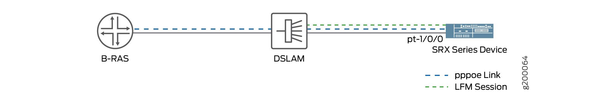
This example uses an SRX Series Firewall connected to a DSLAM. Before you begin configuring Ethernet OAM LFM on these two devices, connect the two devices directly through supported interfaces. See Understanding Ethernet OAM Link Fault Management for SRX Series Services Gateways.
Figure 2 shows the topology used in this example.
For more information about configuring Ethernet OAM Link Fault Management, see Junos® OS Ethernet Interfaces.
Configuration for Scenario 1
To configure remote loopback mode on a VDSL interface, perform these tasks:
Configuring Remote Loopback Mode on a VDSL interface of an SRX Series Device
CLI Quick Configuration
To quickly configure this example, copy the
following command, paste it into a text file, remove any line breaks,
change any details necessary to match your network configuration,
copy and paste the command into the CLI at the [edit] hierarchy
level, and then enter commit from configuration mode.
set protocols oam ethernet link-fault-management interface pt-1/0/0
set protocols oam ethernet link-fault-management interface pt-1/0/0 negotiation-options allow-remote-loopback
Step-by-Step Procedure
To configure remote loopback mode on a VDSL interface of an SRX Series Firewall:
Enable OAM on a VDSL interface.
[edit protocols oam ethernet link-fault-management]
user@device2# set interface pt-1/0/0
Enable remote loopback support for the interface.
[edit protocols oam ethernet link-fault-management]
user@device2# set interface pt-1/0/0 negotiation-options allow-remote-loopback
Results
From configuration mode, confirm your configuration
by entering the show protocols command. If the output does
not display the intended configuration, repeat the configuration instructions
in this example to correct it.
[edit]
user@device2# show protocols
protocols {
    oam {
        ethernet {
            link-fault-management {
                interface pt-1/0/0 {
                    negotiation-options {
                        allow-remote-loopback;
                    }
                }
            }
        }
    }
}
Configuration for Scenario 2
To configure remote loopback mode on a PPPOE’s underlying interface, perform these tasks:
Configuring Remote Loopback Mode on a PPPOE’s underlying interface
CLI Quick Configuration
To quickly configure this example, copy the
following command, paste it into a text file, remove any line breaks,
change any details necessary to match your network configuration,
copy and paste the command into the CLI at the [edit] hierarchy
level, and then enter commit from configuration mode.
set interfaces pp0 unit 0 pppoe-options underlying-interface pt-1/0/0
set protocols oam ethernet link-fault-management interface pt-1/0/0 link-discovery active
set protocols oam ethernet link-fault-management interface pt-1/0/0 negotiation-options allow-remote-loopback
Step-by-Step Procedure
To configure remote loopback mode on a PPPOE’s underlying interface:
Create the PPPoE interface pp0 and specify the logical PT interface pt-1/0/0 as the underlying interface.
[edit protocols oam ethernet link-fault-management]
user@device2# set interfaces pp0 unit 0 pppoe-options underlying-interface pt-1/0/0
Specify that the interface initiates the discovery process.
user@device2# set protocols oam ethernet link-fault-management interface pt-1/0/0 link-discovery active
Enable remote loopback mode.
user@device2# set protocols oam ethernet link-fault-management interface pt-1/0/0 negotiation-options allow-remote-loopback
Results
From configuration mode, confirm your configuration
by entering the show protocols command. If the output does
not display the intended configuration, repeat the configuration instructions
in this example to correct it.
[edit]
user@device2# show protocols
protocols {
    oam {
        ethernet {
            link-fault-management {
                interface pt-1/0/0 {
                    link-discovery active;
                    negotiation-options {
                        allow-remote-loopback;
                    }
                }
            }
        }
    }
}
Verification
Verify the OAM LFM Configuration
Purpose
Verify that OAM LFM is configured properly.
Action
From operational mode, enter the show oam ethernet
link-fault-management command.
user@device1> show oam ethernet link-fault-management
Interface: pt-1/0/0.0
Status: Running, Discovery state: Send Any
Transmit interval: 300ms, PDU threshold: 3 frames, Hold time: 900ms
Peer address: 2001:db8:e5:b9:c8:ed
Flags:Remote-Stable Remote-State-Valid Local-Stable 0x50
Loopback tracking: Disabled, Loop status: Unknown
Remote entity information:
Remote MUX action: forwarding, Remote parser action: forwarding
Discovery mode: active, Unidirectional mode: unsupported
Remote loopback mode: unsupported, Link events: supported
Variable requests: unsupported
Meaning
The output displays the MAC address and the discovery
state is Send Any if OAM LFM has been
configured properly.