Ethernet Alarm Indication
Use Feature Explorer to confirm platform and release support for specific features.
Review the Platform-Specific ETH-AIS Behavior section for notes related to your platform.
Use the following to understand more about Ethernet alarm indication signal (ETH-AIS) and how to configure ETH-AIS on devices.
Ethernet Alarm Indication Signal (ETH-AIS) Function Overview
Ethernet alarm indication signal (ETH-AIS) function enables a service provider deploying an Ethernet service to determine whether a connectivity fault exists at the provider’s domain level or at a level below. When the fault occurs at the provider’s domain level, the service provider addresses the fault, and when the fault occurs at a level below, the provider can either ignore the fault or contact the relevant authorities to address the fault.
The following sections explain ETH-AIS, few use cases which determine when to generate and propagate ETH-AIS packets, and associated terms in detail:
Understand ETH-AIS in a Maintenance Domain
ITU-T developed Y.1731 as a recommendation for Operation, Administration, and Maintenance (OAM) functions and mechanisms for Ethernet-based networks, including OAM functions such as ETH-AIS, Ethernet locked signal (ETH-LCK), Ethernet test signal (ETH-Test), Ethernet automatic protection switching (ETH-APS), Ethernet maintenance communication channel (ETH-MCC), Ethernet experimental OAM (ETH-EXP), Ethernet vendor-specific OAM (ETH-VSP), and performance monitoring. For information about maintenance domain and related terms, see Terms Defined.
According to the Y.1731 standards, a server MEP is a combined function of the server layer termination function and the server Ethernet services layer adaptation function. The server MEP notifies the Ethernet services (ETH) layer MEPs when it detects a failure. The server layer termination function then runs the OAM mechanisms specific to the server layer and the alarms are suppressed at the server layer by ETH-AIS.
Note that ETH-AIS is not applicable to Spanning Tree Protocol (STP) networks.
ETH-AIS enables you to suppress alarms when a fault condition is detected. Using ETH-AIS, a service provider can differentiate between faults at different levels.
ETH-AIS provides many advantages that include:
-
Service providers need not raise alarms if there are lower-level failures.
-
Service providers can provide a refund to their subscribers or avail a refund from their Internet provider based on service unavailability.
Routers support ITU-T Y.1731 ETH-AIS to provide fault management for service providers who provide carrier Ethernet services using IEEE 802.1ag standard.
Fault Detection in a Maintenance Domain
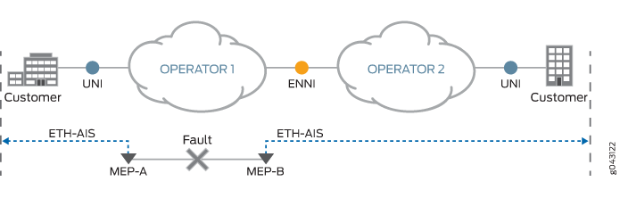
In the scenario depicted in Figure 1 on page xyz, you have a service provider level and a customer level. Two service providers—Operator-1 and Operator-2—are considered for illustration purposes. Assume that a fault occurs in Operator-1 maintenance domain-level that has MEP-A and MEP-B at its maintenance domain-level boundaries. To notify the faults to a network management system and to avoid notification of alarms from the customer level for the same fault, MEP-A and MEP-B transmit an alarm indication signal (AIS) on opposite directions, thereby signaling the higher levels and the Operator-2 network about the fault, so that the alarms are suppressed.
Signaling is achieved through transmission and propagation of AIS protocol data units (PDUs). You must enable AIS explicitly on all the MEPs at the service provider level. A MEP that is configured to issue frames with ETH-AIS information is generally at the server layer and continues to transmit periodic frames with ETH-AIS information until the defect condition is cleared. When a client MEP receives the ETH-AIS frames, it suppresses loss-of-continuity alarms associated with its peer MEPs.
Note that in the absence of AIS, a client MEP resumes generating loss-of-continuity alarms when it detects the loss-of-continuity defect conditions from its server layer.
For point-to-point Ethernet services layer connectivity, a MEP has only one peer MEP. Therefore, there is no ambiguity regarding the peer MEP for which the MEP should suppress alarms when it receives the ETH-AIS information.
For multipoint Ethernet services layer connectivity, a MEP that receives ETH-AIS information cannot determine the exact MEP that encountered the fault and, therefore, cannot isolate the exact peer MEP to suppress the alarms. To avoid this scenario, Y.1731 recommends suppressing alarms for all peer MEPs in the same domain level irrespective of connectivity status in a multipoint Ethernet services layer connectivity setup.
Table 1 lists the operational mode commands that you can use in a maintenance domain to check the various parameters pertaining to a MEP.
|
To Check |
Operational Mode Commands |
|---|---|
|
Whether the AIS configuration is configured correctly on a CFM MEP. |
|
|
Statistics of AIS frames. |
|
|
Whether any event has occurred that triggered AIS. |
|
|
Status of CFM sessions for faults that trigger AIS on the MEP. |
|
Terms Defined
-
AIS transmission—A MEP upon detecting a defect condition transmits AIS frames in a direction opposite to its peer MEPs. The periodicity of AIS frames transmission is on the basis of the AIS transmission period. An AIS transmission period of 1 second is recommended. The first AIS frame must always be transmitted immediately following the detection of a defect condition.
-
AIS reception—Upon receiving an AIS frame, a MEP examines it to ensure that the frame’s maintenance domain level is the same as its own maintenance domain level. The period field in the frame indicates the period at which the AIS frames can be expected. When a MEP receives an AIS frame, it detects the defect condition. After detection, when no AIS frames are received within an interval of 3.5 times—the AIS transmission period indicated in the AIS frames received—the MEP clears the AIS defect condition. When the AIS condition is cleared and defects still exist, then the MEPs continue to report alarms.
-
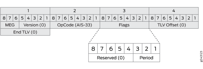
AIS PDU format—The fields of the AIS PDU format are:
-
MEG Level—Also called the maintenance domain level, it is a 3-bit field that is used to carry the maintenance domain level of the client MEG.
-
Version—Value is always 0.
-
OpCode—Value for this PDU type is AIS (33).
-
Flags—The first five bits are reserved and are set to 0. The 3-bit information element carried in the three least significant bits are referred to as the period that contains the value of AIS transmission periodicity as illustrated in Table 2:
Table 2: AIS Transmission Periodicity Flags [3:1]
Period Value
Comments
000-011
Invalid value
Invalid value for AIS
100
1s
1 frame per second
101
Invalid value
Invalid value for AIS
110
1 min
1 frame per minute
111
Invalid value
Invalid value for AIS
-
TLV offset—Set to 0.
-
End TLV—All-zeroes octet value.
-
-
Server layer and client layer—These layers are part of the ITU-T Recommendation G.805 transport network functional model. This model is based on the concept of layering within a transport network. A transport network is divided into several independent transport layer networks that have a client-server association between adjacent layer networks.
-
Maintenance domain—To enable connectivity fault management (CFM) on an Ethernet interface, maintenance domains, maintenance associations, and maintenance end points (MEPs) are created and configured in a network. You can configure up to eight maintenance domain levels in a network. Each maintenance domain level is a part of the network where the connectivity issues can be monitored and corrected. Provider domain and customer domain are some examples for maintenance domains. Each maintenance domain has a maintenance association. Each maintenance association includes MEPs and maintenance intermediate points (MIPs) in that domain. The MEPs are located at the boundary of the domain and the MIPs are located within the domain. MEPs generate and transmit continuity check messages (CCMs) at configured intervals to the entire maintenance association to check the connectivity in the network.
-
Ethernet services (ETH) layer—A layer in the metro Ethernet network model, where this layer is responsible for the OAM services that are required to support the Ethernet services in the network.
ETH-AIS Overview
Routers support ITU-T Y.1731 ETH-AIS to provide fault management for service providers. ETH-AIS enables you to suppress alarms when a fault condition is detected. Using ETH-AIS, an administrator can differentiate between faults at customer level or faults at provider level.
The advantages of ETH-AIS are:
Customers need not raise alarms due to lower level failures.
Customers can get refund based on service unavailability.
When a fault condition is detected, a maintenance end point (MEP) generates ETH-AIS packets to the configured client levels for a specified duration until the fault condition is cleared. Any MEP configured to generate ETH-AIS packets signals to a level higher than its own. A MEP receiving ETH-AIS recognizes that the fault is at a lower level and then suppresses alarms at current level.
Alarm indication signaling is done through the transmission and propagation of ETH-AIS PDUs. ETH-AIS should be enabled on MEPs. A MEP which is configured to issue packets with ETH-AIS information is generally of server layer and continues to transmit periodic packets with ETH-AIS information until the defect condition is cleared. CFM MEPs, upon receiving ETH-AIS PDUs, suppresses loss of continuity alarms associated with its peer MEPs. A MEP resumes loss of continuity alarm generation upon detecting loss of continuity defect conditions in the absence of an ETH-AIS condition.
For point-to-point Ethernet connectivity, a MEP has only a single peer MEP. Therefore, a MEP suppress alarms on its peer MEP when it receives the ETH-AIS information.
For multi-point Ethernet connectivity, a MEP which receives ETH-AIS information cannot determine the exact MEP encountered a fault condition and therefore it will not be able to isolate the exact peer MEP for alarm suppression. ITU-T Y.1731 recommends suppressing alarms for all peer MEPs irrespective of the connectivity status.
AIS transmission—A MEP upon detecting a defect condition transmits ETH-AIS PDUs in a direction opposite to its peer MEPs. The transmission of ETH-AIS PDUs is based on a configured ETH-AIS transmission period. An ETH-AIS transmission period of 1 second is recommended. The first ETH-AIS PDU must be transmitted immediately following the detection of a defect condition.
AIS reception—A MEP upon receiving ETH-AIS PDUs examines it to ensure that its maintenance domain (MD) level corresponds to the same MD level. Upon receiving an ETH-AIS PDU, the MEP detects a defect condition. Following the detection of a defect condition, if there are no ETH-AIS PDUs received within an interval of 3.5 times the ETH-AIS transmission period indicated in the ETH-AIS PDUs received earlier, the MEP clears the defect condition. After the fault condition is cleared, MEPs continue to report alarms.
The following limitations are for server MEP:
Triggering of ETH-AIS messages over services (Layer 2 circuit and Layer 2 VPN) by the link-loss server MEP is done on a best-effort manner. This is because the transmission of ETH-AIS messages is independent of the service status and there is no guarantee for delivering the ETH-AIS messages before service goes down.
Pseudowire protection with CFM-MEP session is not monitored by the server-MEP because an entity to monitor pseudowire protection already exists for the service (Layer 2 circuit and Layer 2 VPN).
Configure ETH-AIS
Routers support ITU-T Y.1731 Ethernet alarm indication signal (ETH-AIS) function to provide fault management for service providers. ETH-AIS enables the service provider to suppress alarms when a fault condition is detected.
You must note the following points when ETH-AIS is configured in CFM MEP:
Transmitting or receiving of AIS on a MEP does not override the
lowest-priority-defectstatement configured at the[edit protocols oam ethernet connectivity-fault-management maintenance-domain domain-name maintenance-association ma-name mep mep-id]hierarchy level. Therefore, alarms are reported according to the defect priority configured.Alarms are reported even when the higher domain levels exchange CCMs at a faster rate than the lower domain levels.
Maintenance association intermediate point (MIP) is transparent to ETH-AIS frames—that is, the MIPs do not perform any action in response to ETH-AIS frames.
When the service provider requests the MEP to generate an AIS for a lower level or for the same level, the request is rejected.
AIS generation is stopped when the MEP clears the remote MEP within the maintenance association.
When the
auto-discoverystatement is enabled for a MEP, the remote MEP information is cleared after the configured hold interval expires.
To support ETH-AIS transmission, the following configuration information is required by a CFM MEP:
-
Client Maintenance Entity Group level—Maintenance Entity Group (MEG) level at which the immediate client layer Maintenance Domain Intermediate Points (MIPs) and Maintenance Association End Points (MEPs) exist.
-
ETH-AIS transmission period—Determines the ETH-AIS PDU transmission interval.
-
Priority—Determines the priority of packets with ETH-AIS information. This is optional.
To support ETH-AIS transmission, the following configuration information required by a server MEP:
-
Server MEP definition—Defines the association of server MEP identifier to the server layer.
-
For Layer 2 circuit and Layer 2 VPN, the logical interface connected to a customer network (UNI) would be the identifier for the server layer that needs to be monitored by the server MEP.
-
For physical link loss detection, the physical interface under Ethernet protocol would be the identifier for the server layer that needs to be monitored by the server MEP.
-
-
Association of server MEP defect—Defines the association of server MEP defects to ETH-AIS action.
-
Association action profile and server MEP—Defines the binding of server MEP and action profile.
To configure ETH-AIS in CFM MEP, you need to configure an action profile for ETH-AIS, configure an action to be taken when an AIS alarm is detected, and attach the action profile to the CFM MEP.
To configure ETH-AIS in server MEP, you need to create an action profile with ETH-AIS action for server MEP defects and attach the action profile to a server MEP.
The following tasks explain how to enable ETH-AIS in CFM MEP and server MEP:
- Configure an Action Profile
- Configure an Action to Be Taken When an AIS Alarm Is Detected
- Attach the Action Profile to a CFM MEP
- Configure ETH-AIS in server MEP
Configure an Action Profile
To configure an action profile for ETH-AIS:
Configure an Action to Be Taken When an AIS Alarm Is Detected
Configure an action to be taken when an AIS alarm is detected.
Attach the Action Profile to a CFM MEP
After configuring an event and an action to be monitored in an action profile, you must attach the action profile to a CFM MEP.
Configure ETH-AIS in server MEP
To create an action profile, include the following statements at the [edit protocols oam ethernet connectivity-fault-management] hierarchy level:
[edit protocols oam ethernet
              connectivity-fault-management]
action-profile action-profile-name {
event {
server-mep-defects {
link-loss-defect;
l2circuit-defect;
l2vpn-defect;
}
}
action {
log-and-generate-ais {
level 1…n;
interval 1 second | 1 minute;
priority dot1p [range 0-7];
}
}
}
To attach an action profile to a server MEP, include the following statement at the [edit protocols oam ethernet connectivity-fault-management] hierarchy level:
[edit protocols oam ethernet connectivity-fault-management]
server-mep  mep-identifier {
    protocol l2circuit | l2vpn | ethernet {
        interface interface-name;
    }
    action-profile action-profile-name;
}
Platform-Specific ETH-AIS Behavior
Use Feature Explorer to confirm platform and release support for specific features.
Use the following table to review platform-specific behaviors for your platform.
| Platform | Difference |
|---|---|
|
ACX Series |
|
|
MX Series |
|