CFM Monitoring between CE and PE Devices
Use this topic to understand more about CFM monitoring between provider edge devices and customer edge devices when the customer edge device is not a Juniper device. Also, you can understand more about how Interface Status TLVs, Port Status TLVs, Chassis ID TLVs, and connection protection TLVs help in monitoring your network.
CFM Action Profile Asynchronous Notification
CFM driven asynchronous notification enables link status synchronization between two CE devices connected to each other through a pseudo wire originating from their respective PE devices. It emulates the scenario as if two CE devices are directly connected. CFM provides end-to-end signaling even if PE1 and PE2 are not connected through single network but a set of networks.
Layer 2 connectivity between PE1 and PE2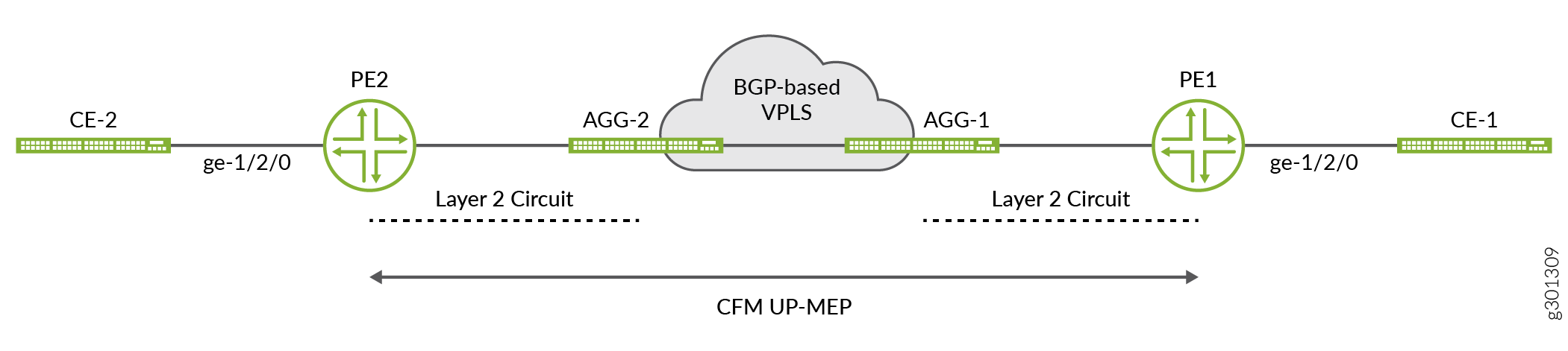
Figure 1 is an example of deployment scenario where CFM based asynchronous-notification can be used to synchronize link status between CE1 and CE2. Following two requirements can be met with the configuration of asynchronous-notification.
-
When the link between PE2 and CE2 goes down then the link between PE1 and CE1 also goes down. When the link is restored, it restores the link status between PE1 and CE1. The link status change between PE1 and CE1 should work similarly.
-
When there is a connectivity issue between PE1 and PE2, it triggers a link down between PE1 and CE1 and PE2 and CE2. If the connection status is restored, it should restore the link status on both ends.
Configure a CFM Action Profile to Asyncronus Notification
CFM UP-MEP on PE1 and PE2, monitors the connectivity between PE1 and PE2. The
interface-status-tlv on these UP-MEP end points conveys the link status
between
PE1,
CE1,
and
PE2, as well as between
PE2,
CE2,
and
PE1. You must configure the action profile on PE1 to PE2 to drive asynchronous notifications
toward the respective CE devices. The action profile triggers those notifications when the
system detects adjacency loss or a link-down condition in the received
interface-status-tlv.
Understand CFM Monitoring between CE and PE Devices
You can enable connectivity fault management (CFM) monitoring between provider edge devices and customer edge devices when the customer edge device is not a Juniper device. When the interface goes down, CFM propagates the status of the interface in the CC messages. The CC message notifies the customer edge device that the provider edge device is down.
You can configure CFM monitoring using either of the following two options:
Interface Status TLV (Type, Length, and Value)—You can enable connectivity fault management (CFM) monitoring between provider edge devices and customer edge devices when the customer edge device is not a Juniper device by using Interface Status TLV. When the interface goes down, CFM propagates the status of the interface using interface status TLV. The Interface Status TLV indicates the status of the interface that hosts the MEP transmitting the CCM, or it indicates the next-lower interface in the IETF RFC 2863 IF-MIB. Thus, the customer edge device learns that the provider edge device is down. To configure CFM monitoring using Interface Status TLV, use the
interface-status-tlvstatement at the[edit protocols oam ethernet connectivity-fault-management maintenance-domain maintenance-domainmaintenance-association maintenance-association continuity-checkhierarchy level. This configuration is the standard option.RDI (Remote Defect Indication)—You can enable connectivity fault management (CFM) monitoring between provider edge devices and customer edge devices when the customer edge device is not a Juniper device by using the RDI bit. When you enable CFM monitoring, CFM propagates the status of the provider edge device through the RDI bit in the CC messages, which informs the customer edge device that the provider edge device is down. The RDI bit is cleared when the service is back up. To configure CFM monitoring using the RDI bit, use the
interface-status-send-rdistatement at the[edit protocols oam ethernet connectivity-fault-management maintenance-domain maintenance-domainmaintenance-association maintenance-association continuity-checkhierarchy level. This option is required if the customer edge device does not support Interface Status TLV.
When you set the interface to CCC down and configure RDI, the device sends the RDI bit. CFM does not monitor the interface status.
If you set CCC down while the interface is not on standby and configure RDI, the device includes the RDI bit in CC messages.
Single Active Multi-homing Use Case using RDI bit
Consider the following topology, which includes two provider edge devices (PE1 and PE2) and two customer edge devices (CE1 and CE2). PE1 operates in the active state, whereas PE2 stays in the standby state. When you configure CFM down MEP between the PE and CE, CFM detects that the CCC is down and the system includes the RDI bit in the CC messages. The CC messages from PE2 to CE2 have the RDI bit set to indicate the blocked state. When PE2 becomes active, the system clears the CCM down status and removes the RDI bit from subsequent CC messages.
Active/Active Multi-homing Use Case using RDI bit
Consider the following topology, which includes two provider edge devices (PE1 and PE2) and two customer edge devices (CE1 and CE2). PE1 operates in the active state, whereas PE2 stays in the standby state. When you do not configure CFM down MEP between the PE and CE to monitor the link connectivity, the system does not include the RDI bit in the CC messages. When you configure CFM down MEP between the PE and CE, CFM detects that the CCC is down and the system includes the RDI bit in the CC messages. The CC messages from PE2 to CE2 have the RDI bit set to indicate the blocked state. When PE2 becomes active, the system clears the CCM down status and removes the RDI bit from subsequent CC messages.
Configure Port Status TLV and Interface Status TLV
- TLVs Overview
- Various TLVs for CFM PDUs
- Support for Additional Optional TLVs
- MAC Status Defects
- Configure Remote MEP Action Profile Support
- Monitor a Remote MEP Action Profile
TLVs Overview
Type, Length, and Value (TLVs) are described in the IEEE 802.1ag standard for CFM as a method of encoding variable-length and/or optional information in a PDU. TLVs are not aligned to any particular word or octet boundary. TLVs follow each other with no padding between them.
Table 1 shows the TLV format and indicates if it is required or optional.
Parameter |
Octet (sequence) |
Description |
|---|---|---|
Type |
1 |
This field is required. If the value is 0, no further fields (Length or Value) follow. If the value is not 0, the Length field must follow. |
Length |
2–3 |
This field is required only if the Type field is not 0. It is not present if the Type field is 0. The 16 bits of the Length field indicate the size, in octets, of the Value field. A Length field value of 0 signifies that there is no Value field. |
Value |
4 |
This field's length is specified by the Length field. It is optional and will not be present if the Type field is 0 or if the Length field is 0. |
Various TLVs for CFM PDUs
Table 2 shows a set of TLVs defined by IEEE 802.1ag for various CFM PDU types. Each TLV can be identified by the unique value assigned to its Type field. Some Type field values are reserved.
TLV or Organization |
Type Field |
|---|---|
End TLV |
0 |
Sender ID TLV |
1 |
Port Status TLV |
2 |
Data TLV |
3 |
Interface Status TLV |
4 |
Reply Ingress TLV |
5 |
Reply Egress TLV |
6 |
LTM Egress Identifier TLV |
7 |
LTR Egress Identifier TLV |
8 |
Reserved for IEEE 802.1 |
9 to 30 |
Organization-Specific TLV |
31 |
Defined by ITU-T Y.1731 |
32 to 63 |
Reserved for IEEE 802.1 |
64 to 255 |
Not every TLV is applicable for all types of CFM PDUs.
TLVs applicable for continuity check message (CCM):
End TLV
Sender ID TLV
Port Status TLV
Interface Status TLV
Organization-Specific TLV
TLVs applicable for loopback message (LBM):
End TLV
Sender ID TLV
Data TLV
Organization-Specific TLV
TLVs applicable for loopback reply (LBR):
End TLV
Sender ID TLV
Data TLV
Organization-Specific TLV
TLVs applicable for linktrace message (LTM):
End TLV
LTM Egress Identifier TLV
Sender ID TLV
Organization-Specific TLV
TLVs applicable for linktrace reply (LTR):
End TLV
LTR Egress Identifier TLV
Reply Ingress TLV
Reply Egress TLV
Sender ID TLV
Organization-Specific TLV
The following TLVs are currently supported in the applicable CFM PDUs:
End TLV
Reply Ingress TLV
Reply Egress TLV
LTR Egress Identifier TLV
LTM Egress Identifier TLV
Data TLV
Support for Additional Optional TLVs
The following additional optional TLVs are supported:
Port Status TLV
Interface Status TLV
MX Series routers support configuration of port status TLV and interface status TLV. Configuring the Port Status TLV allows the operator to control the transmission of the Port Status TLV in CFM PDUs.
For configuration information, see the following sections:
Port Status TLV
The Port Status TLV indicates the ability of the bridge port
on which the transmitting MEP resides to pass ordinary data, regardless
of the status of the MAC. The value of this TLV is driven by the MEP
variable enableRmepDefect, as shown in Table 4. The format of this TLV
is shown in Table 3.
Any change in the Port Status TLVs value triggers one extra transmission of that bridge ports MEP CCMs.
Parameter |
Octet (Sequence) |
|---|---|
Type = 2 |
1 |
Length |
2–3 |
Value (See Table 4) |
4 |
Mnemonic |
Ordinary Data Passing Freely Through the Port |
Value |
|---|---|---|
psBlocked |
No: |
1 |
psUp |
Yes: |
2 |
The MEP variable enableRmepDefect is a boolean variable. It
indicates whether frames on the service instance monitored by the maintenance
associations of the MEP can pass through the bridge port using the Spanning Tree
Protocol and VLAN topology management. It is set to TRUE if:
The bridge port is set in a state where the traffic can pass through it.
The bridge port is running multiple instances of the spanning tree.
The MEP interface is not associated with a bridging domain.
- Configure Port Status TLV
- Display the Received Port Status TLV
- Display the Transmitted Port Status TLV
Configure Port Status TLV
Junos OS provides configuration support for the Port Status TLV, allowing you to control the
transmission of the TLV in CCM PDUs. The Junos OS provides this
configuration at the continuity-check level. By default, the CCM does not
include the Port Status TLV. To configure the Port Status TLV, use the
port-status-tlv statement at the [edit
protocols oam ethernet connectivity-fault-management maintenance-domain
identifier maintenance-association
identifier continuity-check] hierarchy
level.
Port Status TLV configuration is not mandated by IEEE 802.1ag. The Junos OS provides this configuraion in order to give more flexibility to the operator; however it receives and processes CCMs with a Port Status TLV, regardless of the configuration.
An example of the configuration statements follows:
protocols {
    oam {
        ethernet {
            connectivity-fault-management {
                maintenance-domain identifier {
                    level number;
                    maintenance-association identifier {
                        continuity-check {
                            interval number,
                            loss-threshold number;
                            hold-interval number;
                            port-status-tlv; # Sets Port Status TLV
                        }
                    }
                }
            }
        }
    }
}
You cannot enable Port Status TLV transmission in the following two cases:
If the MEP interface under the maintenance-association is not of type bridge.
If the MEP is configured on a physical interface.
Display the Received Port Status TLV
The Junos OS saves the last received Port Status TLV from a
remote MEP. If the received Port Status value does not correspond
to one of the standard values listed in Table 4, then the show command displays it as "unknown." You can display the last saved
received Port Status TLV using the show oam ethernet connectivity-fault-management
mep-database maintenance-domain identifier maintenance-association identifier local-mep identifier remote-mep identifier command, as in the following example:
user@host> show oam ethernet connectivity-fault-management mep-database maintenance-domain md5 maintenance-association ma5 local-mep 2001 remote-mep 1001
Maintenance domain name: md5, Format: string, Level: 5
  Maintenance association name: ma5, Format: string
  Continuity-check status: enabled, Interval: 100ms, Loss-threshold: 3 frames
  MEP identifier: 2001, Direction: down, MAC address: 00:19:e2:b2:81:4a
  Auto-discovery: enabled, Priority: 0
  Interface status TLV: up, Port status TLV: up
  Interface name: ge-2/0/0.0, Interface status: Active, Link status: Up

  Remote MEP identifier: 1001, State: ok
    MAC address: 00:19:e2:b0:74:00, Type: Learned
    Interface: ge-2/0/0.0
    Last flapped: Never
    Remote defect indication: false
    Port status TLV: none # RX PORT STATUS
    Interface status TLV: none
Display the Transmitted Port Status TLV
The Junos OS saves the last transmitted Port Status TLV from
a local MEP. If the transmission of the Port Status TLV has not been
enabled, then the show command displays "none." You can
display the last saved transmitted Port Status TLV using the show oam ethernet connectivity-fault-management mep-database maintenance-domain identifier maintenance-association identifier local-mep identifier remote-mep identifier command, as in the following example:
user@host> show oam ethernet connectivity-fault-management mep-database maintenance-domain md5 maintenance-association ma5 local-mep 2001 remote-mep 1001
Maintenance domain name: md5, Format: string, Level: 5
  Maintenance association name: ma5, Format: string
  Continuity-check status: enabled, Interval: 100ms, Loss-threshold: 3 frames
  MEP identifier: 2001, Direction: down, MAC address: 00:19:e2:b2:81:4a
  Auto-discovery: enabled, Priority: 0
  Interface status TLV: up, Port status TLV: up # TX PORT STATUS
  Interface name: ge-2/0/0.0, Interface status: Active, Link status: Up

  Remote MEP identifier: 1001, State: ok
    MAC address: 00:19:e2:b0:74:00, Type: Learned
    Interface: ge-2/0/0.0
    Last flapped: Never
    Remote defect indication: false
    Port status TLV: none
    Interface status TLV: none
Interface Status TLV
The Interface Status TLV indicates the status of the interface on which the MEP transmitting the CCM is configured, or the next-lower interface in the IETF RFC 2863 IF-MIB. The format of this TLV is shown in Table 5. The enumerated values are shown in Table 6.
Parameter |
Octet (Sequence) |
|---|---|
Type = 4 |
1 |
Length |
2–3 |
Value (See Table 6) |
4 |
Mnemonic |
Interface Status |
Value |
|---|---|---|
isUp |
up |
1 |
isDown |
down |
2 |
isTesting |
testing |
3 |
isUnknown |
unknown |
4 |
isDormant |
dormant |
5 |
isNotPresent |
notPresent |
6 |
isLowerLayerDown |
lowerLayerDown |
7 |
When the operational status of a logical interface changes from the down state (status value of 2) to the lower layer down state (status value of 7) and vice versa, the LinkDown SNMP trap is not generated. For example, if you configure an aggregated Ethernet interface bundle with a VLAN tag and add a physical interface that is in the operationally down state to the bundle, the operational status of the aggregated Ethernet logical interface bundle at that point is lower layer down (7). If you take the MIC associated with the interface offline, the LinkDown trap is not generated when the logical interface shifts from the lower layer down state to the down state.
Similarly, consider another sample scenario in which an physical interface is added to an aggregated Ethernet bundle that has VLAN tagging and the aggregated Ethernet logical interface is disabled. When the logical interface is disabled, the operational status of the logical interface changes to down. If you disable the physical interface that is part of the aggregated Ethernet bundle, the operational status of the aggregated Ethernet logical interface remains down. If you reenable the aggregated Ethernet logical interface, the operational status of it changes from down to lower layer down. The LinkDown SNMP trap is not generated at this point.
- Configure Interface Status TLV
- Display the Received Interface Status TLV
- Display the Transmitted Interface Status TLV
Configure Interface Status TLV
The Junos OS provides configuration support for the Interface Status TLV, thereby allowing operators to control the transmission of this TLV in CCM PDUs through configuration at the continuity-check level.
This configuration is not mandated by IEEE 802.1ag; rather it is provided to give more flexibility to the operator. The Junos OS receives and processes CCMs with the Interface Status TLV, regardless of this configuration.
The interface status TLV configuration is shown below:
protocols {
    oam {
        ethernet {
            connectivity-fault-management {
                maintenance-domain identifier {
                    level number;
                    maintenance-association identifier {
                        continuity-check {
                            interval number;
                            loss-threshold number;
                            hold-interval number;
                            interface-status-tlv; # Sets the interface status TLV
                        }
                    }
                }
            }
        }
    }
}
The Junos OS supports transmission of only three out of seven possible values for the Interface Status TLV. The supported values are 1, 2, and 7. However, the Junos OS is capable of receiving any value for the Interface Status TLV.
Display the Received Interface Status TLV
The Junos OS saves the last received Interface Status TLV from
the remote MEP. If the received Interface Status value does not correspond
to one of the standard values listed in Table 5, then the show command displays "unknown."
You can display this last saved Interface Status TLV using the show oam ethernet connectivity-fault-management mep-database maintenance-domain identifier maintenance-association identifier local-mep identifier remote-mep identifier command, as in the following example:
user@host> show oam ethernet connectivity-fault-management mep-database maintenance-domain md5 maintenance-association ma5 local-mep 2001 remote-mep 1001

Maintenance domain name: md5, Format: string, Level: 5
  Maintenance association name: ma5, Format: string
  Continuity-check status: enabled, Interval: 100ms, Loss-threshold: 3 frames
  MEP identifier: 2001, Direction: down, MAC address: 00:19:e2:b2:81:4a
  Auto-discovery: enabled, Priority: 0
  Interface status TLV: up, Port status TLV: up
  Interface name: ge-2/0/0.0, Interface status: Active, Link status: Up

  Remote MEP identifier: 1001, State: ok
    MAC address: 00:19:e2:b0:74:00, Type: Learned
    Interface: ge-2/0/0.0
    Last flapped: Never
    Remote defect indication: false
    Port status TLV: none
    Interface status TLV: none # displays the Interface Status TLV state
Display the Transmitted Interface Status TLV
The Junos OS saves the last transmitted Interface Status TLV
from a local MEP. If the transmission of Interface Status TLV has
not been enabled, then the show command displays "none."
You can display the last transmitted Interface Status TLV using
the show oam ethernet connectivity-fault-management mep-database
maintenance-domain identifier maintenance-association identifier local-mep identifier remote-mep identifier command, as in the following example:
user@host> show oam ethernet connectivity-fault-management mep-database maintenance-domain md5 maintenance-association ma5 local-mep 2001 remote-mep 1001

Maintenance domain name: md5, Format: string, Level: 5
  Maintenance association name: ma5, Format: string
  Continuity-check status: enabled, Interval: 100ms, Loss-threshold: 3 frames
  MEP identifier: 2001, Direction: down, MAC address: 00:19:e2:b2:81:4a
  Auto-discovery: enabled, Priority: 0
  Interface status TLV: up, Port status TLV: up
  Interface name: ge-2/0/0.0, Interface status: Active, Link status: Up

  Remote MEP identifier: 1001, State: ok
    MAC address: 00:19:e2:b0:74:00, Type: Learned
    Interface: ge-2/0/0.0
    Last flapped: Never
    Remote defect indication: false
    Port status TLV: none
    Interface status TLV: none
MAC Status Defects
The Junos OS provides MAC status defect information that indicates when remote MEPs
report failures in their Port Status TLV or Interface Status TLV. The system
indicates "yes" if, one or more remote MEPs report that their interface is not "Up"
(for example, when a remote MEP's interface is unavailable) or if, all remote MEPs
report a Port Status TLV with some value other than "Up" (for example, when all
remote MEPs' bridge ports are not forwarding data). You can view the MAC Status
Defects indication using two show commands.
Use the mep-database command to display MAC status defects:
user@host> show oam ethernet connectivity-fault-management mep-database maintenance-domain md6 maintenance-association ma6
Maintenance domain name: md6, Format: string, Level: 6
  Maintenance association name: ma6, Format: string
  Continuity-check status: enabled, Interval: 1s, Loss-threshold: 3 frames
  MEP identifier: 500, Direction: down, MAC address: 00:05:85:73:7b:39
  Auto-discovery: enabled, Priority: 0
  Interface status TLV: up, Port status TLV: up
  Interface name: xe-5/0/0.0, Interface status: Active, Link status: Up
  Defects:
    Remote MEP not receiving CCM            : no
    Erroneous CCM received                  : no
    Cross-connect CCM received              : no
    RDI sent by some MEP                    : no
    Some remote MEP's MAC in error state    : yes # MAC Status Defects yes/no
  Statistics:
    CCMs sent                               : 1658
    CCMs received out of sequence           : 0
    LBMs sent                               : 0
    Valid in-order LBRs received            : 0
    Valid out-of-order LBRs received        : 0
    LBRs received with corrupted data       : 0
    LBRs sent                               : 0
    LTMs sent                               : 0
    LTMs received                           : 0
    LTRs sent                               : 0
    LTRs received                           : 0
    Sequence number of next LTM request     : 0
    1DMs sent                               : 0
    Valid 1DMs received                     : 0
    Invalid 1DMs received                   : 0
    DMMs sent                               : 0
    DMRs sent                               : 0
    Valid DMRs received                     : 0
    Invalid DMRs received                   : 0
  Remote MEP count: 1
    Identifier    MAC address        State    Interface
      200     00:05:85:73:39:4a       ok    xe-5/0/0.0
Use the interfaces command to display MAC status defects:
user@host> show oam ethernet connectivity-fault-management interfaces detail
Interface name: xe-5/0/0.0, Interface status: Active, Link status: Up
  Maintenance domain name: md6, Format: string, Level: 6
    Maintenance association name: ma6, Format: string
    Continuity-check status: enabled, Interval: 1s, Loss-threshold: 3 frames
    Interface status TLV: up, Port status TLV: up
    MEP identifier: 500, Direction: down, MAC address: 00:05:85:73:7b:39
    MEP status: running
    Defects:
      Remote MEP not receiving CCM                  : no
      Erroneous CCM received                        : no
      Cross-connect CCM received                    : no
      RDI sent by some MEP                          : no
      Some remote MEP's MAC in error state          : yes # MAC Status Defects yes/no
    Statistics:
      CCMs sent                                     : 1328
      CCMs received out of sequence                 : 0
      LBMs sent                                     : 0
      Valid in-order LBRs received                  : 0
      Valid out-of-order LBRs received              : 0
      LBRs received with corrupted data             : 0
      LBRs sent                                     : 0
      LTMs sent                                     : 0
      LTMs received                                 : 0
      LTRs sent                                     : 0
      LTRs received                                 : 0
      Sequence number of next LTM request           : 0
      1DMs sent                                     : 0
      Valid 1DMs received                           : 0
      Invalid 1DMs received                         : 0
      DMMs sent                                     : 0
      DMRs sent                                     : 0
      Valid DMRs received                           : 0
      Invalid DMRs received                         : 0
    Remote MEP count: 1
      Identifier    MAC address        State    Interface
        200     00:05:85:73:39:4a       ok    xe-5/0/0.0
Configure Remote MEP Action Profile Support
Based on values of interface-status-tlv and
port-status-tlv in the received CCM packets, a specific
action, such as interface-down, can be taken using the
action-profile options. Multiple action profiles can be
configured on the router, but only one action profile can be assigned to a
remote MEP.
The action profile can be configured with one or more events, and the action
triggers when any one of these events occurs. It is not necessary for all of the
configured events to trigger action.
An action-profile can be applied only at the remote MEP level.
The following example shows an action profile configuration with explanatory comments added:
[edit protocols oam ethernet connectivity-fault-management]
action-profile tlv-action {
    event {
        # If interface status tlv with value specified in the config is received
        interface-status-tlv down|lower-layer-down;

        # If port status tlv with value specified in the config is received
        port-status-tlv blocked;

        # If connectivity is lost to the peer */
        adjacency-loss;
    }
    action {
        # Bring the interface down */
        interface-down;
    }
    default-actions interface-down;
    }

# domains
    maintenance-domain identifier {
        # maintenance domain level (0-7)
        level number;

        # association
        maintenance-association identifier {
            mep identifier {
                interface ge-x/y/z.w;

                remote-mep identifier {
                    # Apply the action-profile for the remote MEP
                    action-profile tlv-action;
                }
            }
        }
    }
Monitor a Remote MEP Action Profile
You can use the show oam ethernet connectivity-fault-management
mep-database command to view the action profile status of a
remote MEP, as in the following example:
show oam ethernet connectivity-fault- management mep-database remote-mep (Action Profile Event)
user@host> show oam ethernet connectivity-fault-management mep-database maintenance-domain md5 maintenance-association ma5 remote-mep 200
Maintenance domain name: md5, Format: string, Level: 5
  Maintenance association name: ma5, Format: string
  Continuity-check status: enabled, Interval: 1s, Loss-threshold: 3 frames
  MEP identifier: 100, Direction: down, MAC address: 00:05:85:73:e8:ad
  Auto-discovery: enabled, Priority: 0
  Interface status TLV: none, Port status TLV: none  # last status TLVs transmitted by the router
  Interface name: ge-1/0/8.0, Interface status: Active, Link status: Up

  Remote MEP identifier: 200, State: ok # displays the remote MEP name and state
    MAC address: 00:05:85:73:96:1f, Type: Configured
    Interface: ge-1/0/8.0
    Last flapped: Never
    Remote defect indication: false
    Port status TLV: none
    Interface status TLV: lower-layer-down
    Action profile: juniper  # displays remote MEP’s action profile identifier
      Last event: Interface-status-tlv lower-layer-down  # last remote MEP event
                                                         # to trigger action
      Action: Interface-down, Time: 2009-03-27 14:25:10 PDT (00:00:02 ago)
                              # action occurrence time
Configure Chassis ID TLV
You can configure Junos OS to send the Sender ID TLV along with the packets. The Sender ID TLV is an optional TLV that is sent in continuity check messages (CCMs), loopback messages, and Link Trace Messages (LTMs), as specified in the IEEE 802.1ag standard. The Sender ID TLV contains the chassis ID, which is the unique, CFM-based MAC address of the device, and the management IP address, which is an IPv4 or an IPv6 address.
The value of the length field in the TLV indicates
whether or not the TLV contains the chassis ID information. The possible
values for the length field are zero (0) or
any valid number, which indicates the absence or presence of chassis
ID information in the TLV, respectively.
You can enable Junos OS to send the Sender ID TLV at the global level by using the set
protocols oam ethernet connectivity-fault-management sendid-tlv
send-chassis-tlv command. If the Sender ID TLV is configured at the global
level, then the default maintenance domain, maintenance association, and the maintenance
association intermediate point (MIP) half function inherit this configuration.
You can also configure the Sender ID TLV at the following hierarchy levels:
[edit protocols oam ethernet connectivity-fault-management][edit protocols oam ethernet connectivity-fault-management maintenance-domain maintenance-domain-name maintenance-association maintenance-association-name continuity-check]
The Sender ID TLV configuration at the maintenance-association level takes
precedence over the global-level configuration.
The Sender ID TLV is supported only for 802.1ag PDUs and is not supported for performance monitoring protocol data units (PDUs).
Configure MAC Flush Message Processing in CET Mode
In carrier Ethernet transport (CET) mode, MX Series routers are used as provider edge (PE) routers, and Nokia Siemens Networks A2200 Carrier Ethernet Switches (referred to as E-domain devices) that run standard-based protocols are used in the access side. On the MX Series routers, VPLS pseudowires are configured dynamically through label distribution protocol (LDP). On the E-domain devices, topology changes are detected through connectivity fault management (CFM) sessions running between the E-domain devices and the MX Series PE routers. The MX Series PE routers can bring the carrier Ethernet interface down if there is CFM connectivity loss. This triggers a local MAC flush as well as a targeted label distribution protocol (T-LDP) MAC flush notification that gets sent towards the remote MX Series PEs to trigger MAC flush on them.
In CET inter-op mode, MX Series routers need to interoperate with the Nokia Siemens Networks Ax100 Carrier Ethernet access devices (referred to as A-domain devices) that run legacy protocols. Nokia Siemens Networks A4100 and A8100 devices act as an intermediate between the MX Series PE routers and A-domain devices. These intermediate devices perform interworking function (IWF) procedures so that operations administration management (OAM) sessions can be run between MX Series routers and A-domain devices. There are no VPLS pseudowires between the MX Series PE routers and the Nokia Siemens Networks A4100 and A8100 intermediate devices, so there is no LDP protocol running between the PE routers to send topology change notifications. In order to communicate topology changes, MX Series routers can trigger a MAC flush and propagate it in the core. MX Series routers can use action profiles based upon the connection protection type length value (TLV) event. The action profile brings down the carrier edge logical interface in MX Series PE routers, which will trigger a local MAC flush and also propagate the topology change to the core using LDP notification.
For VPLS there is no end-to-end connectivity monitored. The access rings are independently monitored by running CFM down multiple end points (MEPs) on the working and protection paths for each of the services between the E-domain devices and the MX Series PE routers, and between the A-domain devices and the MX Series PE routers the IWF hosted by the Nokia Siemens Networks A-4100 devices. When there is a connectivity failure on the working path, the Nokia Siemens Networks Ax200 devices perform a switchover to the protection path, triggering a topology change notification (in the form of TLVs carried in CCM) to be sent on the active path.
Figure 1 describes the dual homed topology on MX Series PE routers connected to the A-domain. When an A-domain device triggers a switchover, it starts switching the service traffic to the new active path. This change is communicated in the HELLO protocol data units (PDUs) sent by that A-domain device on the working and protection paths. When the IWF in A4100 recieves these HELLO PDUs, it converts them to standard CCM messages and also inserts a connection protection TLV. The “Protection-in-use” field of the connection protection TLV is encoded with the currently active path, and is included in the CCM message. CCM messages are received by the MX Series PE routers through the VLAN spoke in A4100. In the above dual homed scenario, one MX Series PE router monitors the working path, and the other MX Series PE router monitors the protection path.
A MAC flush occurs when the CFM session that is monitoring the working path detects that the service traffic has moved to the protection path or when the CFM session that is monitoring the protection path detects that the service traffic has moved to the working path.
Figure 2 describes the dual attached topology on MX Series PE routers connected to the A-domain. The MAC flush mechanism used in this case is also the same as the one used for the A-domain in the dual homed scenario (Figure 1). However in this case both the CFM sessions are hosted by only one MX Series PE router. When Ax100 in the A-domain detects topology changes, the MX Series PE router receives the connection protection TLV in the CCM message for the working and protection paths with the value of “Protection-in-use” indicating which path is the active one. Based upon the event that is generated for the CFM session, the MX Series PE router will bring down the appropriate interface which will trigger a local MAC flush.
Configure a Connection Protection TLV Action Profile
An action profile can be configured to perform the interface-down action based on the values of connection-protection-tlv in the received CCM packets.
The following example shows an action profile configuration with explanatory comments added:
[edit protocols oam ethernet connectivity-fault-management]
action-profile <tlv-action> {
    event {
        # If a connection protection TLV with a “Protection-in-use” value of SET is received */
        connection-protection-tlv <using-protection-path>;
        # If a connection protection TLV with a “Protection-in-use” value of RESET is received */
        connection-protection-tlv <using-working-path>;
    }
    action {
        # Bring the interface down */
        interface-down;
    }
}
Example: Configure an Action Profile Based on Connection Protection TLVs
This example shows how to configure an action profile based on the connection protection TLV for the purposes of triggering MAC flushes based on topology changes in a CET network.
Requirements
This example uses the following hardware and software components:
Junos OS Release 11.2 or later
A MX series PE router
Overview and Topology
The physical topology of a CET network using MX series PE routers is shown in Figure 3.
Topology

The following definitions describe the meaning of the device abbreviation and terms used in Figure 3.
Provider edge (PE) device—A device or set of devices, at the edge of the provider network that presents the provider's view of the customer site.
E-domain—Nokia Siemens Networks Carrier Ethernet Switches that run standard based protocols and are used in the access side.
A-domain—Nokia Siemens Networks Carrier Ethernet Switches that run legacy protocols.
Configuration
Step-by-Step Procedure
To configure an action profile based on the connection protection TLV, preform these tasks:
Configure an action profile
[edit protocols oam ethernet connectivity-fault-management]
action-profile <tlv-action> {
    event {
    }
}
If the connection protection TLV is received with a “Protection-in-use” value of SET, then the connection protection TLV should use the protection path
connection-protection-tlv <using-protection-path>;
If the connection protection TLV is received with a “Protection-in-use” value of RESET, then the connection protection TLV should use the working path
connection-protection-tlv <using-working-path>;
Configure the action profile to bring the interface down
action {
    /* Bring the interface down */
    interface-down;
}
Results
Check the results of the configuration
[edit protocols oam ethernet connectivity-fault-management]
action-profile <tlv-action> {
    event {
        connection-protection-tlv <using-protection-path>;
        connection-protection-tlv <using-working-path>;
    }
    action {
        interface-down;
    }
}
Change History Table
Feature support is determined by the platform and release you are using. Use Feature Explorer to determine if a feature is supported on your platform.